 ?Mathematical formulae have been encoded as MathML and are displayed in this HTML version using MathJax in order to improve their display. Uncheck the box to turn MathJax off. This feature requires Javascript. Click on a formula to zoom.
Abstract
Studies on the modeling and simulation of the railway vehicle traction system play an active role in the operation and planning phase of railway electrification. In this paper, the longitudinal dynamic of a light rail vehicle was modelled and simulated in Matlab-Simulink. The traction system consists of two parallel motor groups, each of which is composed of two seperately-excited motors connected in series. The first simulation scenario represents how the traction system works in acceleration and braking modes with respect to a given speed change profile. Within this scenario, the time dependent responses of the motor armature and excitation currents, fluxes, motor traction moment, adhesion, resistance forces and acceleration are evaluated, and the constant torque, field attenuation, operation zones and vehicle traction force curve are described. The second simulation scenario represents the slip control application, which examines the complex nonlinear relationship between the adhesion force and the slip ratio, were demonstrated. Modified super-twisting sliding mode slip control are performed under dry, wet and low wheel-rail contact conditions, which are sequentially switched. It has been confirmed by the simulation results that the proposed control strategy achieves the maximum adhesion force of the train. The main purposes of this study are to investigate the operation principles of the railway dynamics associated with acceleration or braking modes and to examine the effects of certain parameters related with the dynamical electromechanical traction system.
Public Interest Statement
Railway vehicles are constantly being developed to shorten travel times. Therefore, they need powerful traction system to meet increasing speed demands. The development of traction control strategies to achieve optimal traction ensures that safe and effective driving, while reducing unwanted slip phenomenon occured between the wheel-rail. The behavior of a railway vehicle with bogie traction, which the slip control strategy was implemented, was evaluated by using simulation approach to achieve more effective results in terms of optimizing traction conditions. The railway traction consists of two motor groups and each motor group is connected in series. The traction system was modeled and simulated to investigate the motor stator currents, traction torque, adhesion and resistance forces with respect to a given reference speed profile. The adhesion force was calculated during a simulation scenario under different contact conditions. The simulation results confirm that the proposed control strategy achieve the optimal slip ratio.
1. Introduction
The railway vehicles are divided into three class with their kind of energy usage as steam, diesel fueled and electric. Steam locomotives provide steam energy from the combustion of fuels that supply energy to the locomotives. Steam locomotives operate at short distance since locomotives can not be loaded over a certain amount of fuel used. For this reason, usage of steam system has been completely removed. Diesel fueled locomotives have diesel motors as a source of energy. A train, which pulls ten wagon can take approximately 600–700 km distance according to its fuel tank. On the contrary, electric locomotives have no refueling problems, so they can travel long distances. The electric locomotives are the most economical locomotive because of the tractive effort. The railway vehicles are also classified by their usage type as EMU, DEMU, railbus, light railway system, heavy railway system, high speed railway system etc. The light rail system is an urban electric transport system with its own special way at ground level or elevated roads that can be operated as a single or multiple vehicles. On the other hand, locomotives and wagons are accepted as heavy railway systems. Only those, which perform the traction function are categorized as locomotive. Locomotives differ among themselves depending on power transmission systems. Passenger and freight transport vehicles used in railways are called wagons. The first electric trains were DC motor systems, which the low voltage fed from third rail was applied to the electric motors via resistors. Widespread DC voltage systems are 600 V, 750 V, 1,500 V, 3 kV, respectively. AC Electrification systems are classified as 25 kV–50 Hz, 15 kV–16.7 Hz, 25 kV–60 Hz, respectively. For example, the British Rail Class 92 is a dual-voltage electric locomotive, which can operate from both 750 V DC third rail and 25 kV–50 Hz. AC from overhead wires (The train book, Citation2014). Positive aspects of the electric traction systems are; the production, operation and maintenance of electric locomotives and multiple units are less costly than diesel engines; the fact that electric trains have higher power ratios than diesel ones and allow faster acceleration, higher power reach, and higher speeds; they have low operating noise and no power loss at high altitudes, regenerative braking is possible using super capacitors, respectively. Negative aspects of the electric traction systems are; electrification costs are high, renewal of some structures that are not high enough for the catenary line may also be required; it is necessary to renew the signaling system; the national network may be overloaded and reserve power stations may be required to construct; the catenary feeding system may experience some mechanical damage and service may be hindered, respectively. From the energy efficiency pointview, the electric trains are more effective than diesel ones. Electric trains emit less carbon dioxide than diesel trains. As compared with the electric train, diesel trains include clutch system and fuel weights while electric trains contain heavy equipment like transformer. The total efficieny in the electric train system is higher than the diesel train (White, Citation2010). Power is transmitted using DC or single-phase AC networks in electric railway locomotives. The development of traction technology has led to the production of different electrification systems. Railway networks are influenced by factors such as operational requirements (urban metro, fast transport or heavy freight transport), physical road features (gradients, bridges and tunnels), traction technology (converters, traction motors, regenerative capability) (Hill, Citation1994). Nevertheless, the nonlinear interaction between the wheel-rail, which is critical force for the train operation, has been intensively studied in the existing literature. The motor of the trains only provides traction torque to the wheels and the main movement of the train is carried out under the influence of the adhesion force (Wickens, Citation1986). Super-twisting algorithm was developed by Davila, Fridman, and Levant (Citation2005), on the basis of sliding mode control theory. It was applied to real engineering problems in order to stabilize fast time-varying systems.
In this paper, the railway vehicle is driven by direct current motor with seperately excitation. Each wagon has four traction motor with nominal power of 75 kW, three bogies, and two wheelsets for each bogie. Each traction motor was installed on each wheelset in the front and rear bogies. Two motors in one bogie are operated with both armature and excitation circuits in series. There are two control loop in the system. First one is the control of excitation currents and second one is the control of the armature currents. The control of the excitation current is based on the induced voltage. A reference between the induced voltage value and the motor induced voltage value is passed through the PI controller, and the excitation current reference value to be applied to the motor is obtained. At the same time with this control cycle, field attenuation is ensured and the motor reaches to the desired high speed values. In order to form the control loop, it is first necessary to obtain the induced voltage reference value. For this purpose, the reference values of the DC line voltage and the rotor current to be applied to the motor are utilized (Krause, Citation1986). The armature current control is based on the reference value of the acceleration taken from the control arm of the wagon control room. The acceleration value used as the feedback signal is obtained by taking derivative of the generated voltage, which is proportional to the motor speed, after filtering with the low-pass filter. With the feedback signal from the motor speed, this speed value is first converted to a linear speed value. After that, the acceleration value, that can be compared with the reference acceleration is obtained by filtering and taking its derivative. The acceleration error is fed to a PI controller and reference q-current is produced. The difference between the reference current and the measured motor current is fed to an another PI controller and the control signal to be applied to the drive circuit is produced. The generated control signal is compared with the triangular wave and applied to the GTO, which is connected to the motor groups in series. The motor current is controlled by PWM pulse generator.
The first simulation scenario was carried out to inspect how the traction system behaves in acceleration and braking modes and the second simulation scenario was carried out to evaluate the performance of the super-twisting sliding mode slip control under various wheel-rail contact conditions. In the first part, the traction system model is explained in detail, in the second part the power supply of the traction system is modeled and proposed control algorithm is described in the third part, followed by simulation results and conclusion.
2. Material and method
2.1. Traction system modeling
In this study, it has been focused on a light railway vehicle having three bogies, two wheelsets in each bogie, four traction motors, which is mounted on each corresponding wheelset by a gearbox, and six brake discs on each wheelset, respectively. Position, speed and acceleration rate are important variables of railway vehicle dynamics. During the train movement, relations among these variables are extracted according to Newton’s second law of motion. The adhesion forces occurred at the wheel-rail contact is the key factor in acceleration or braking mode. Tractive or braking effort must be exerted to the wheels in order to emerge these adhesion forces. While this torque is produced by an motor or brake system, a certain amount of energy is translated into the required mechanical energy. What needs to be done here is to produce a simple model based on energy perspective. This model must include all the steps from the torque generated by the motor to the wheel-rail contact. As a result of all these effects, the train speeds up or slows down. In Figure , the railway vehicle is moving on a sloped track surface. This movement is mathematically represented using a free-body diagram that describes all external forces acting on the train as shown in Equation (1) There are resistance forces acting opposite to the train movement and are classified into frictional forces, air resistance and gravitational force, respectively. The resistance forces are represented in Equation (2)(1)
(1)
(2)
(2)
where Fτ designates the tractive force of the train, FR designates the total resistance force of the train, is the rolling resistance force,
denotes the aerodynamic drag force,
is the gradient gravity force of the train,
is the arc resistance,
is the acceleration of the train,
refers to the total effective mass of the train and defined as in Equation (3)
(3)
(3)
where ng is the gear reduction ratio, is the gear efficiency, r0 is the nominal rolling radius of the wheel, Jm is the total motor inertia
;
, mr is the motor mass, rr is the radius of the rotor shaft, l is total number of the traction system set, Jw is the total sum of the right and left wheel inertia,
.
where, n is the number of the wheelset in each bogie, m is the number of the bogie, mw is the wheelset mass, is the total static mass of the train, which is represented in Equation (4) as:
(4)
(4)
where is the passenger mass,
is the vehicle body mass, mw is the mass of the single wheel, mx is axle mass,
is the mass of the brake system,
,
are bogie masses,
is the total mass of the traction motor, mg denotes the gearbox mass.
The slip ratio of a train () can be stated in Equation (5) as
(5)
(5)
V is the forward vehicle velocity, ωw is the angular velocity of the wheel.
Rolling resistance is the resistance created by the movement of rotating parts of the train. It is originated from the frictional torques such as bearing torques, rotor, brake pads, axles, gear teeth friction etc. The mathematical expression of the rolling resistance is shown in Equation (6).(6)
(6)
where
,
,
are roll resistance parameters, respectively.
The movement of the railway vehicle takes place against the airflow, and the force that the air applies to the train affects the longitudinal movement of the train. The aerodynamic force is due to the common effects of the pressure difference between the front and the rear of the train, air seperation, which results vortex formation behind the vehicle, and the surface roughness of the vehicle body related with the skin friction. The parametric relationship of the aerodynamic resistance force is shown in the Equation (7).(7)
(7)
where is the air density
, Cd is an aerodynamic drag coefficient, Av is the frontal section of the train. These parameters can be represented by a single parameter as k2.
A gradient force acts on the opposite direction to the movement of the train moving upwards on a road with slope. The gradient force is constant under the constant slope condition. Equation (8) represents the mathematical form of the gradient force.(8)
(8)
g is the gravitational constant, ϕg is the gradient.
The arc resistance force is originated due to friction between the wheel and rail when the railway vehicle is moving along a curve. It can be stated with an empirical Röckl formula (Steimel, Citation2008) in Equation (9) as(9)
(9)
Ry is the radius of the track curvature.
Cr1 and parameters change with respect to the radius of the track curvature as
The wheelset dynamics of the train can be given considering adhesion at the wheel-rail contact in Equation (10) as(10)
(10)
Te is the motor torque, Fa is the adhesion force, Bm is the viscous friction torque coefficient, is the equivalent moment of inertia of the motor
Jg is the gear inertia, is the break system inertia, Jx is the axle inertia.
The adhesion force occurs as a result of the moving wheel-rail contact and defined in Equation (11) as
(11)
(11)
where is the adhesion coefficient, which is a nonlinear function of the slip ratio.
The relationship between the adhesion coefficient and slip ratio is defined by using Burckhardt model (Kiencke & Nielsen, Citation2000) in Equation (12) as(12)
(12)
α1, α2, α3 are parameters, which change with various wheel-rail contact conditions.
2.2. Traction power supply
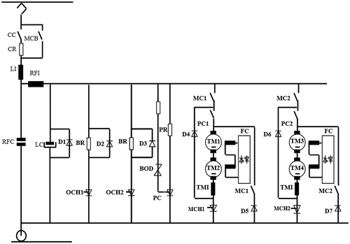
In Figure the power circuit related to the traction system is given.
The parameters of the power circuit is defined as; D1, D2, D3, D4, D5, D6, D7 are diodes, Li, RFC are inductance and capacity for inlet filter, RFI is a radio filter inductance, LC is the filter capacity, BR is the braking resistance, OCH1, OCH2 are braking chopper, PR is the overvoltage resistance, PCH is the overvoltage chopper, MC1, MC2 are motor main contactor, PC1, PC2 are motor operation contactors, MCH1, MCH2 are motor current adjustment choppers, TMI is the motor current filtering inductance, TM1, TM2, TM3, TM4 are traction motors, FC1, FC2 are excitation current chopper circuit. The traction system consists of two parallel motor groups, each of which consist of two seperately excitation DC motors connected in series. The excitation ends of the motor groups, which their armature ends are connected to each other in series, are also connected in series. The motor groups are connected via an inductance and a direct current filter consisting of a capacitor group to a DC voltage network, which its voltage value changes between 500 and 900 V. Both the armature and excitation currents of the direct current motor with seperately excitation are controlled for changing the speeds of the motors, acceleration, deceleration and braking control processes. The armature current is changed by GTOs (Gate turn-off thyristor) connected to each motor group in series. For this purpose, there is a filter consisting of series connected inductors to the motor groups and GTO’s to prevent current fluctuations and possible moment oscillations of motors driven by PWM (pulse width modulation) pulses with switching frequency 69–207 Hz. The power supply also includes overvoltage protection circuits in order to prevent voltage boosts in the power stage, braking diodes and DC voltage network. The excitation ends of the motors are connected in series and fed by a phase full wave controlled rectifier. The alternative voltage required by the rectifier is provided by an inverter that is fed from the DC bus, consisting of GTOs and switched by PWM. The inverter is also used in other circuits fed by the alternating current in the circuit at the same time. These are power electronic circuits used to fill AC fans and car battery accumulators (Zhang, Rehtanz, & Pal, Citation2012). In the equivalent circuit; Rq, Lq, vq, iq, Lf, Rf, if, vf, eb are the equivalent armature resistance, the equivalent armature inductance, armature voltage, armature current, excitation inductance, excitation resistance, excitation current, excitation voltage, induced voltage, respectively. Flux and current relations have nonlinear relationship. At the same time, the armature reaction is considered in the equivalent circuit. In the system, two direct current motors are connected in series and TMI filter is added. TMI filter is modeled with an inductance L2 and winding resistance R2. Initially, the capacitor-battery pack at the filter input is empty. By switching off the CC switch, the series connected CR (capacitor charging resistor) starts to charge up the 18.8 mF capacitance group over 20.25 Ω resistance with a maximum 37 A current. After approximately one second CC opens and main circuit breaker MCB is turned off. The excitation currents of the motors have risen to about 22 A value over the rectifier. The motors are now ready for action. The MC1, MC2, PC1, and PC2 switches are turned off. When the motors are running, the GTO is driving the GTO with PWM pulses. This means that GTO is in transmission during time and in cutting during
time.
, where
and f is 69–207 Hz. Within the periods that correspond to these values, the GTO will be in one segment in a transmission state and in one segment in cutting state. Two seperate equivalent circuits for cutting and transmission are mentioned and will be examined seperately. Models related with the subgroups in the system have been obtained as considering the filter stage at the input, motor groups and TMI filter connected in series to those motors. A more realistic model of the nonlinear structure, including the saturation and armature reaction of the linear relationships as the flux-current relationship, is given in Equation (13).
(13)
(13)
The moment equations of the motor groups are
and the total moment is the sum of the moments of both motor groups .
This moment will compensate the load moments that the wagon makes and provide the desired acceleration. Since the motors are connected to the wheels via the gear system, they are converted to the induced moment force magnitude, taking into account the turning ratio and yield of the gear system. The difference between the force acting on the wheel and the load force will be the acceleration force. The effective mass portion of this force will give the wagon acceleration. Motor currents do not suddenly become zero while the GTO is off, and the close their paths through the D4 and D6 diodes, which are connected to their groups. In this case, no current is drawn from the network and the capacitor battery. When the motor current decreases in this short time, the capacitor voltage also increases from de DC network. Since the inductance reduces the sudden change of the current, this change in current does not affect the motor speeds. In this case, there is no change in the motor’s excitation current.
The traction force for each motor when the kinetic energy of the whole system increases, changes in Equation (14) as.
(14)
(14)
The moment produced by the motor is evaluated in Equation (15) as(15)
(15)
where kt is the motor moment constant, ϕ is the magnetic flux value, is the motor armature current.
Motor magnetic flux can be obtained from the motor magnetization curve (Terzic, Despalatovic, & Slutej, Citation2012) values as given in Equation (16)(16)
(16)
The parameter values are; ξ = 2.59427, = 0.08563,
= 0.000021, δ = 1.534537.
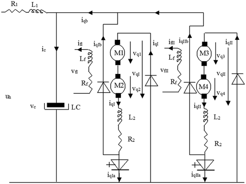
During braking, current is drawn to operate motor as generator. The torque directions must be changed in order to make motors brake. Since only one direction of current can flow from the GTO, the direction of the excitation current must be changed (Vuchic, Citation2007). Since the excitation circuit is composed of phase-wave controlled rectifiers connected in parallel oppositely to each other, the directional change in the excitation current can be provided by switching from one rectifier group to another. For this purpose, first the motor armature current is made to go to zero, then the excitation current is inverted by the conduction of the other rectifier group which is connected in reverse after a rectifier group cut. Since the armature current is still flowing in the same direction, the directions of the torques of the motors are change. During braking, the PC1 and PC2 switches are opened to provide two ways for the motor armature current. One of these is the path consisting of D4, D5, D6, and D7 diodes, the LC capacitor group and the motor, and this is the valid when the induced voltage, which drives the braking current in to the DC network, is greater than Vc. The other is the path through which the motor brakes via the MCH1 and MCH2 GTO’s and D5–D7 diodes. The equivalent circuit at the braking mode is depicted in Figure .
While GTOs are in transmission, the motor currents will complete their path from the D5 and D7 diodes. The motor currents will feed the line through D4, D5, and D6, D7 while the GTOs are off. In this case the capacitor group will be fed by both the line voltage and the braking currents of the machines.(17)
(17)
This is the current 2Iq that is transferred to DC bus. If the electrical braking power in the braking system is inadequate, the mechanical disc braking is activated in a controlled manner. The desired braking acceleration is provided in this way. The mechanical brake is activated when the current reference reaches its maximum value. It is necessary to determine the maximum value of the current reference. The value at which the current reference is maximized are given in the form of curves depends on the speed of the wagon, the temperature of the power stage etc. Once the current reference reaches the preset maximum value, the mechanical brake group will assist the electrical brake in the braking of the wagon with PI controller, which is driven by the acceleration error. During the mechanical braking, the current reference is kept at the maximum value of the first reach, which causes the mechanical brake to engage in order to eliminate the increase in braking acceleration after mechanical brake got involved and the decrease in current refrence, also the disadvantage of the inability of fully electrical braking utilization (Zhang, Dai, & Zhou, Citation2011).
2.3. Proposed slip control scheme
If a dynamical system is considered as in Equation (18).(18)
(18)
where u is the controller and is the continuously differentiable external disturbance. As a controller, the following modified version of the super-twisting sliding mode algorithm were used (Chen, Dong, Lu, Sun, & Guo, Citation2016).
(19)
(19)
where γ1, , 1 – 2α + β = 0 and
When the adhesion model is known, the optimal slip ratio can be calculated as
(20)
(20)
Based on the optimal ratio ,
(21)
(21)
The proposed algorithm converges faster than classical super-twisting algorithm.
3. Sımulatıon results
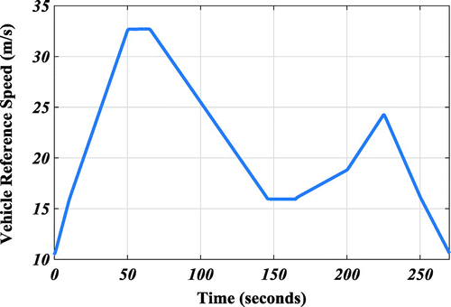
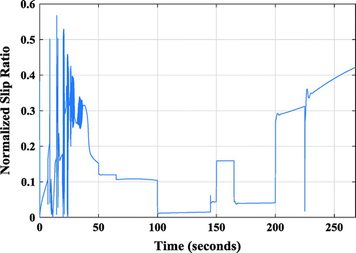
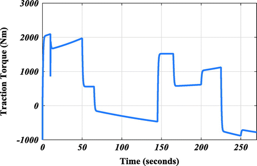
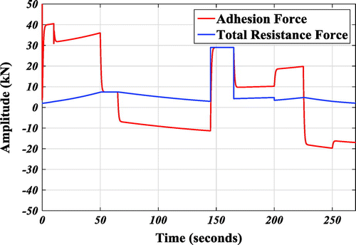
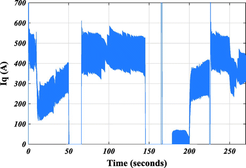
The railway vehicle accelerates in 10 s. with full load and then accelerates with a lower acceleration at t = 10–50 s. At t = 50–65 s, it moves with a constant speed with the same load. At t = 65–145 s, the vehicle speed is decreased. At t = 145–165 s, the vehicle enters to a curved track, which its radius is 60 m. At t = 165–200 s, the vehicle is accelerated while climbing a slope ‰2 with full load. At t = 200 s, the slope climbing process is completed and the vehicle accelerates on the straight road at t = 200–225 s. In the range of t = 225–270 s, the train is braked. This whole changes are shown in Figure .
Curves showing the behavior of the traction system between 0 and 270 s are given in this section. The simulation was conducted with a ode5(Dormand-Prince) fixed-step solver. The electrical and mechanical parameters used in simulation are listed in Table .
Table 1. The electrical and mechanical parameters used in simulation
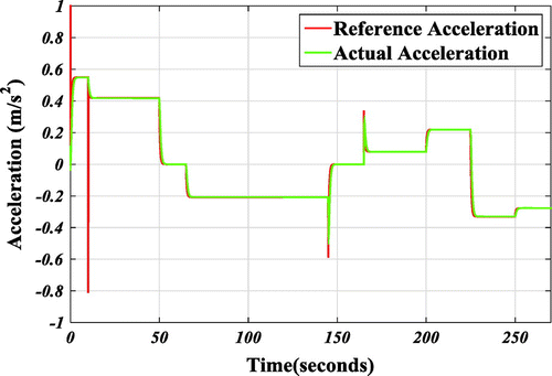
The variation of the actual acceleration filtered and calculated from the motor speeds that move the wagon and the reference acceleration is plotted in Figure .
The slip ratio between 0 and 270 s was evaluated by using the following normalized formula and was depicted in Figure .(22)
(22)
Figure shows the change in the traction force produced by the motors in the wagon.
In Figure , the adhesion force and total resistance forces (load) acting on the wagon is given.
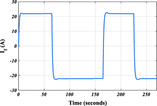
In Figure , the variation of the motor currents obtained by the operation of one of the motor groups in PWM mode of the GTOs is shown at this time interval including both acceleartion and braking.
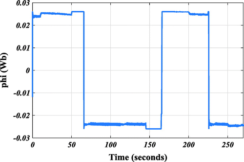
It can be seen that the excitation current in Figure and the excitation flux in Figure are decreasing after a certain period of time. As a result, the speed continues to increase again. The reason for the reduction in the excitation current is that the voltage induced from the motor in the control loop rises with increasing speed, constant excitation current and the excitation curent exceeds the reference value. The excitation current remains constant at a certain value until the motors are braked.
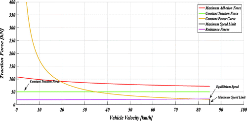
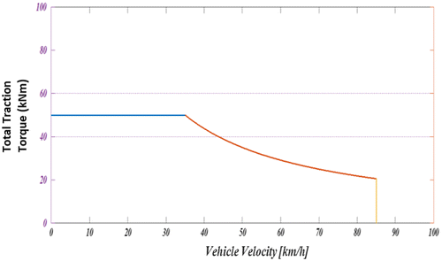
In Figure the traction force curve of the traction system was represented, and the constant torque, field attenuation and speed limit zones of the traction motor are drawn to show the motor-speed characteristic in Figure .
In the second simulation; initial states of the railway vehicle velocity and wheel angular velocity are given as
and
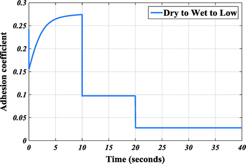
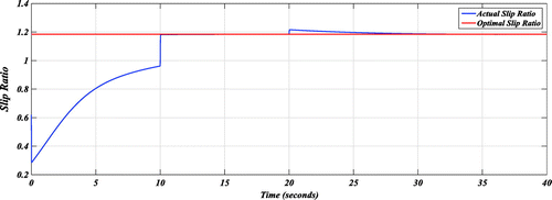
It should be considered that optimal slip ratio switches every 10 s, because the adhesion conditions vary from dry to wet, wet to low, every 10 s.
The trajectories of the railway vehicle speed and wheel speed are given in Figure .
Figure 14. Trajectories of the wheel speed and railway vehicle speed under dry-wet-low adhesion condition.
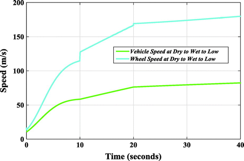
It can be seen that the value of the wheel speed changes suddenly when t = 10 and t = 20 s, which corresponds to the switching points of the optimal slip ratio values.
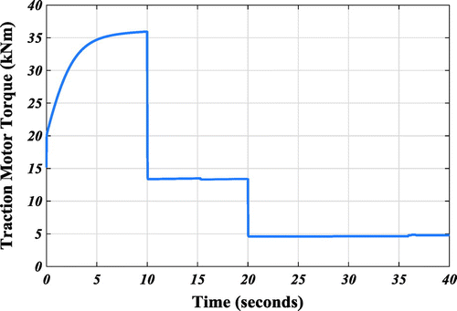
The adhesion coefficient decrease abruptly and wheel slip emerge because of the rail conditions change dry to wet at t = 10 s and wet to low at t = 20 s, respectively. The wheel turns much faster than the vehicle and the slip velocity goes from the safety limit to dangerous area gradually. Then, the wheel slip was detected and the slip control strategy set the traction motor torque in order to suppress the wheel slip and drive the train at optimal slip velocity. The trajectories of the adhesion coefficient is shown in Figure .
The traction motor torque was also reduced while the redundant part of the slip is being attenuated. The trajectory of the traction motor torque is shown in Figure .
The trajectory of the slip ratio, which is calculated based on Equation (5) vs. optimal slip ratio is depicted in Figure .
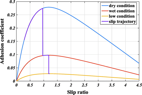
The whole adhesion performance is illustrated in Figure . The actual slip ratio can precisely track the optimal slip ratio through the adhesion characteristic map. The full detail of adhesion coefficient varying in the slip control can be determined from this figure.
The adhesion coefficient converged to a neighborhood of the maximum adhesion value for the dry condition in the initial acceleration phase, after that it suddenly declines to the safe region in the “dry&wet&low” condition adhesion characteristic and converge to the maximum adhesion value of this characteristic function. By using re-adhesion control, the adhesion coefficient remains safe operational region and performs high traction ability provided available adhesion.
4. Conclusion
A motion simulation has been developed so that the railway vehicle can be tested in various situations. This simulation includes the analyzes of rail vehicle dynamics under varying resistance loads and varying wheel-rail contact conditions. The generated electromechanical traction model plays an important role in determining the body forces acting on a train and in selecting suitable traction motor. The operating points of the traction force curves vary depending on vehicle speed, acceleration, vehicle load dynamic, slip and wheel-rail contact mechanics. According to the traction force curve of the system, it can be deduced that, the traction motor exhibits good performance due to the constant traction force curve is always below maximum adhesion force and the equilibrium speed is high. At the same time, the control problem for the optimal use of the adhesion force was investigated. To achieve such a goal, a modified control scheme has been proposed by changing the parameters of the super-twisting algorithm. Train was operated at optimal slip ratio for dry, wet and low conditions, respectively. The results of the presented computer simulation allows an advanced algorithm to obtain a result that can be used to characterize the general and structural characteristics of electromechanical systems with similar design forms. The presented model exhibits transient behavior when the load conditions change in power transmission. The model serves to determine the most suitable traction parameters for the locomotives, for example by selecting the gear ratio of the powertrain.
Funding
The authors received no direct funding for this research.
Additional information
Notes on contributors
Caglar Uyulan
Caglar Uyulan received the BSc degree from Dokuz Eylul University in Mechanical Engineering Department, MSc and PhD degrees from Istanbul Technical University in Mechatronics Engineering in 2008, 2010, and 2017, respectively. From 2012 to 2016, he worked in several projects involving control and design of high speed railway vehicles, and EEG signal processing. His research interests include nonlinear control, signal processing, and mechatronics system modeling.
Metin Gokasan
Metin Gokasan received the BSc, MSc, and PhD degrees from Istanbul Technical University, Istanbul, Turkey, in 1980, 1982, and 1990, respectively, all in electrical and control engineering. From 2004 to 2006, he conducted research at the University of Alaska Fairbanks, Fairbanks, as a visiting scholar and worked in several projects involving the control of HEVs and sensorless control of induction motors. His research interests include the control of electrical machinery, power electronics and electrical drives, control of hybrid electric vehicles, and mechatronics systems.
Seta Bogosyan
Seta Bogosyan received her BSc and MSc degrees from in ITU Electrical Engineering in 1981 and 1983 and conducted her PhD in control engineering jointly in UC Santa Barbara and ITU between 1987 and 1991. She has taught in UCSB in 1991, and served as a professor of electrical engineering at ITU between 1992 and 2003, and then as a professor at the University of Alaska Fairbanks until 2016. She is currently with National Science Foundation (NSF). Her research interests are in cyber-physical systems, control of robots and autonomous platforms, tele-robotics, and open test beds.
References
- Chen, Y., Dong, H., Lu, J., Sun, X., & Guo, L. (2016). A super-twisting-like algorithm and ıts application to train operation control with optimal utilization of adhesion force. IEEE Transactions on Intelligent Transportation Systems, 17, 3035–3044.10.1109/TITS.2016.2539361
- Davila, J., Fridman, L., & Levant, A. (2005). Second-order sliding-mode observer for mechanical systems. IEEE Transactions on Automatic Control, 50, 1785–1789. doi:10.1109/tac.2005.858636
- Hill, R. (1994). Electric railway traction. Part 3: Traction power supplies. Power Engineering Journal, 8, 275–286.10.1049/pe:19940604
- Kiencke, U., & Nielsen, L. (2000). Automotive control systems. Berlin: Springer-Verlag.
- Krause, P. C. (1986). Analysis of electric machinery. Alapakkam: McGraw-Hill.
- Steimel, A. (2008). Electric traction - motive power and energy supply: Basics and practical experience. München: Oldenbourg Industrieverl.
- Terzic, B., Despalatovic, M., & Slutej, A. (2012). Magnetization curve ıdentification of vector-controlled ınduction motor at low-load conditions. Automatika ‒ Journal for Control, Measurement, Electronics, Computing and Communications, 53, 255–262.
- The train book. (2014). The definitive visual history. London: Dorling Kindersley.
- Vuchic, V. R. (2007). Urban transit systems and technology. Hoboken, NJ: John Wiley & Sons.10.1002/9780470168066
- White, R. (2010). DC railway electrification supply system. IET Professional Development Course on Electric Traction Systems.
- Wickens, A. H. (1986). Non-linear dynamics of railway vehicles. Vehicle System Dynamics, 15, 289–301. doi:10.1080/00423118608968857
- Zhang, Z. L., Dai, R. Q., & Zhou, C. F. (2011). The design and simulation test research of electrical mechanical brake. Advanced Materials Research, 421, 526–531.10.4028/www.scientific.net/AMR.421
- Zhang, X., Rehtanz, C., & Pal, B. (2012). Flexible AC transmission systems modelling and control. Berlin: Springer.10.1007/978-3-642-28241-6


