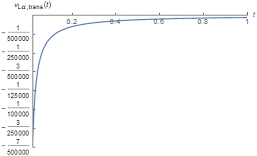
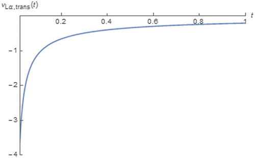
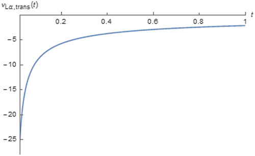
 ?Mathematical formulae have been encoded as MathML and are displayed in this HTML version using MathJax in order to improve their display. Uncheck the box to turn MathJax off. This feature requires Javascript. Click on a formula to zoom.
Abstract
In this research, many novel expressions for time domain responses of fractance device to various often cited inputs have been proposed. Unlike the previous ones, our expressions have been derived based on the Caputo fractional derivative by also concerning the dimensional consistency with the integer order device based responses and the different between two types of fractance device i.e. fractional order inductor and fractional order capacitor. These previous expressions have been derived based on the Riemann-Liouvielle fractional derivative which has certain features that leads to contradictions and additional modeling difficulties unlike the Caputo fractional derivative. Our new expressions are applicable to both fractional order inductor and capacitor with arbitrary order. They are also applicable to any subject which its electrical characteristic can be modeled based on the fractance device. With our expressions and numerical simulations, the time domain behavioral analysis of both fractance device and such subject can be directly performed without requiring any time to frequency domain conversion and its inverse as already presented in this work. Therefore our work has been found to be beneficial to various fractance device related disciplines e.g. biomedical engineering, control system, electronic circuit and electrical engineering etc.
Public Interest Statement
Fractance device is often cited in various scientific disciplines because the electrical characteristics of many subjects range from biological to electronic e.g. botanical tissue, human organ, loudspeaker coil and electrical vehicle battery etc., can be modelled by using such device. Even though such characteristics of those subjects can be experimentally analyzed by direct measurement, this methodology is costly and cumbersome. For obtaining precise analysis results of those subjects with reduced cost and effort, the expressions of the responses of fractance device which is their modeling basis, are helpful. Thus many expressions have been previously derived. Unfortunately, they have certain limitations and disadvantages. This motivates us to derive novel expressions of fractance device’s responses where those limitations and disadvantages have been removed. We also perform the analysis of fractance device and the candidates of those aforesaid subjects by using our expressions and computer simulations.
1. Introduction
Fractance device is an electronic device with fractional order impedance function i.e. such order can be any real value between −1 and 1. The fractance device which the phase of its voltage always leads that of its current thus has positive order, and vice versa are referred to as the fractional order inductor and fractional order capacitor respectively. This device is often cited in various scientific disciplines e.g. biomedical engineering (Barsoukov & Macdonald, Citation2005; Inaba, Manabe, Tsuji, & Iwamoto, Citation1995; Jesus, MacHado, & Cunha, Citation2008; Tang et al., Citation2009), control system (Charef, Citation2006; Jifeng & Yuankai, Citation2005; Vinagre & Feliu, Citation2007), electronic circuit and electrical engineering (Ahmad, El-khazali, & Elwakil, Citation2001; Dorčák, Terpák, Petráš, & Dorčáková, Citation2007; Freeborn, Maundy, & Elwakil, Citation2013; Ma, Zhou, Li, & Chen, Citation2016; Schäfer & Krüger, Citation2006; Stanislavsky, Citation2005) etc. This is because it serves as a basis for the modeling of electrical properties of many subjects e.g. botanical tissues (Elwakil & Maundy, Citation2010; Inaba et al., Citation1995; Jesus et al., Citation2008), human organ (Tang et al., Citation2009), supercapacitors (Freeborn et al., Citation2013), lossy magnetic core inductive coils (Schäfer & Krüger, Citation2006) and Li-ion battery which is applicable to the electric vehicle (Ma et al., Citation2016), etc. For thoroughly analyze the electrical characteristics of these subjects, obtaining the expressions of responses of fractance device which is their modeling basis, is profitable as the precise analysis results can be obtained by using those expressions and numerical simulations. By doing so, much of cost and effort can be significantly reduced compared to the direct measurement of the subject under test excited by the predetermined inputs which is both costly and cumbersome.
By this motivation and many citations of the fractance device, the expressions of time domain responses of fractance device to various inputs have been derived in previous studies e.g. Krishna, Reddy, and Santa Kumari (Citation2008), Elwakil (Citation2010), Radwan and Elwakil (Citation2012a) and Banchuin and Chaisricharoen (Citation2015) etc., based on the Riemann-Liouvielle fractional derivative which has certain features e.g. nonzero derivative of a constant (Atangana & Secer, Citation2013), derivative with one or more singular points of an analytic function and complex valued derivative of a real valued function (Valério, Trujillo, Rivero, Machado, & Baleanu, Citation2013) etc. These features leads to contradictions and additional modeling difficulties e.g. nonzero derivative of a constant is contradict to the fact that a constant is unchanged with respected to any variable, derivative with singular points become nonanalytic i.e. neither mathematically meaningful nor explicitly evaluated, at such points therefore introduces additional modeling difficulties and complex valued derivative introduces additional complex valued function thus also increase the modeling difficulties etc. These previous expressions have also been derived without concerning the dimensional consistencies with the responses of the integer order device i.e. the ordinary inductor and capacitor. Some of them are also applicable only to fractance device with certain magnitudes and orders. Moreover, the aforementioned different between the fractional order capacitor and inductor has not been taken into account.
Hence, the novel expressions of time domain responses of fractance device excited by various renowned inputs e.g. impulse, step, ramp, parabolic, trigonometric and arbitrary periodic input etc., have been derived in this research by also considering the formerly ignored dimensional consistency and different between both types of fractance device i.e. the fractional order inductor and capacitor. Unlike Banchuin and Chaisricharoen (Citation2015), Elwakil (Citation2010), Krishna et al. (Citation2008) and Radwan and Elwakil (Citation2012a), the Caputo fractional derivative which does not have those stated above features, has been adopted as our basis. The derived expressions are applicable to the fractance device of both types with arbitrary order. They are also applicable to any subject that its electrical characteristic can be modeled by using the fractance device such as those mentioned above where the applications to the supercapacitors, lossy magnetic core inductive coils and Lithium-ion battery have been demonstrated. By using our derived expressions and numerical simulations with MATHEMATICA, the time domain behavioral analysis of fractance device e.g. transient and asymptotic behavioral analysis etc., which are as important as the frequency domain based analysis, can be directly performed without requiring either Fourier or Laplace transformation based methodology as already shown in this work. Moreover, such direct time domain behavioral analysis of the supercapacitors, lossy magnetic core inductive coils and Lithium-ion battery have also been demonstrated. So, our work has been found to be beneficial to various fractance device related disciplines e.g. biomedical engineering, control system, electronic circuit and electrical engineering etc.
In Section 2, both Riemann-Liouvielle and Caputo fractional derivative will be introduced followed by a brief revision of the previous works in Section 3. Our basis Caputo fractional derivative based voltage-current relationship of fractance device which the aforesaid different between both types of fractance device and dimensional consistency have been included, will be presented in Section 4. Our proposed expressions and their applications to the aforesaid subject will be subsequently presented in Sections 5 and 6 where the time behavioral and performance analysis will also be shown. Finally, the conclusion will be drawn in Section 7.
2. The fractional derivative
The fractional derivative is the generalizing of the ordinary derivative by allowing the arbitrary fractional value order. For arbitrary function f(t), its Riemann-Liouvielle fractional derivative of arbitrary fractional order, γ with respected to t can be given by Atangana and Secer (Citation2013) and Valério et al. (Citation2013):
(1)
(1)
where m − 1 < γ < m and m can be arbitrary integer. Moreover, Γ() denotes the gamma function which can be mathematically defined in term of arbitrary variable x as:(2)
(2)
On the other hand, the Caputo fractional derivative which has been adopted in this research, can be given as follows (Atangana & Secer, Citation2013; Valério et al., Citation2013):
(3)
(3)
3. Revision of the related previous works
As aforementioned, the Riemann-Liouvielle fractional derivative based expressions of time domain responses of fractance device to many excitations have been previously derived. In Krishna et al. (Citation2008), many expressions which are applicable only to a half order capacitor i.e. a fractance device with the order, α of −0.5, have been proposed. Beside such limit applicability, this work also has other disadvantages e.g. the response to a zero phase shift cosinusoidal input become nonanalytic at the origin as it has a singularity there since it goes to infinity which cannot be explicitly evaluated, etc.
Later, the expressions of response of fractance device excited by a zero phase shift sinusoidal input have been derived in Elwakil (Citation2010) and Radwan and Elwakil (Citation2012a) where Elwakil (Citation2010) is dedicated only to the unity magnitude fractional order capacitor. Even though both fractional order inductor and capacitor have been taken into account in Radwan and Elwakil (Citation2012a), their aforesaid different relationships between phases of voltage and current has been ignored. This is because 0 < α < 1 and −1 < α < 0 for the fractional order inductor and capacitor due to such different so, m must be respectively given by 1 and 0 for these devices for taking this issue into account. Unfortunately, m has been similarly given by 1 for both fractional order inductor and capacitor in this previous work. The expressions proposed in both (Elwakil, Citation2010; Radwan & Elwakil, Citation2012a) are in terms of the generalized trigonometric functions i.e. the generalized sine and cosine function which can be respectively denoted by sinα() and cosα(). These functions can be given as follows (Elwakil, Citation2010; Radwan & Elwakil, Citation2012a, Citation2012b):
(4)
(4)
(5)
(5)
Both cosα() and sinα() can introduce the modeling difficulty since they also become nonanalytic at the origin by having singularities there as they goes to infinity (Radwan & Elwakil, Citation2012a, Citation2012b). Since the expressions proposed in Elwakil (Citation2010) and Radwan and Elwakil (Citation2012a) have been derived by assuming that the excitation current has zero phase shift, they become inapplicable when the nonzero phase shift input is applied. Moreover, both (Elwakil, Citation2010; Radwan & Elwakil, Citation2012a) also neglect the dimensional consistency with the integer order device based responses. This is because they adopted the following voltage-current relationship.(6)
(6)
where v(t) and i(t) stand for the voltage response and input current. Moreover, k = L and k = C for the fractional order inductor and capacitor. Since the dimension of dα/dtα which is adopted in those previous works is s-α (Gómez-Aguilar, Rosales-García, Bernal-Alvarado, Córdova-Fraga, & Guzmán-Cabrera, Citation2012), that of v(t) obtained by using this voltage-current relationship is HAs-α and F−1Asα for the fractional order inductor and capacitor respectively. These dimensions are inconsistent those of v(t) of the ordinary inductor and capacitor given by HAs−1 and F−1As.
Recently, the expression of response to arbitrary periodic input has been proposed in Banchuin and Chaisricharoen (Citation2015). Unfortunately, this previous expression is applicable only to the fractional inductor and the dimensional consistency has also been ignored as (6) has also been adopted in this work. Moreover, such expression is also in term of sinα() and cosα().
4. The basis Caputo fractional derivative based voltage-current relationship of fractance device
For covering the dimensional consistency, the cosmic time, σ (Gómez-Aguilar et al., Citation2012; Podlubny, Citation2002) which has the dimension of s, has been introduced. Therefore (6) become:
(7)
(7)
For simplicity, we let K = k/σ1−α thus we have
(8)
(8)
According to the above definition of k, K = L/σ1−α = Lα which stands for the inductivity (Schäfer & Krüger, Citation2006), for the fractional order inductor. On the other hand, K = 1/σ1−αC = 1/Cα where Cα stands for the pseudo capacitance (Freeborn et al., Citation2013), for the fractional order capacitor. Noted that the dimensions of Lα and Cα are H∙sα−1 (Freeborn et al., Citation2013) and F∙sα−1 (Schäfer & Krüger, Citation2006) respectively. By using (8), the dimension of the obtained v(t) is HAs−1 and F−1As for the fractional order inductor and capacitor which are consistent to those the integer device based v(t).
Since we use the Caputo fractional derivative for defining dα/dtα, we have:(9)
(9)
Finally, as m must be respectively given by 1 and 0 for taking the different between the fractional order inductor and capacitor into account, our basis Caputo fractional derivative based voltage-current relationship of the fractance device can be obtained as follows:(10)
(10)
5. The proposed novel expressions and time domain behavioral analysis of fractance device
By using (10), our novel expressions of fractance’s response to various often cited inputs can be derived and the time domain behavioral analysis of fractance device can be instantly performed by using these expressions as will be presented in the following subsections where the impulse, step, ramp and parabolic function which are aperiodic, will be firstly considered followed by trigonometric and arbitrary periodic function.
5.1. The expressions for impulse, step, ramp and parabolic responses
The response to impulse function i.e. impulse response, has been interested as any system can be conveniently characterized in time domain by using its impulse response since it is the time domain version of the transfer function. In order to derived the expression for impulse response, we let i(t) = Iδ(t) where I and δ() are arbitrary real value and Dirac’s delta function. As a result, the expression of impulse response can be obtained as
(11)
(11)
Since Г(−α + 1) = −αГ(−α), (11) can be reduced to:
(12)
(12)
where K = Lα and K = 1/Cα if the fractance device under consideration is the fractional order inductor and capacitor respectively.
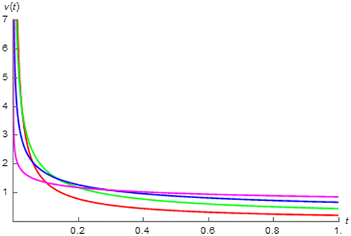
It can be seen that our expression of impulse response i.e. (12), is applicable to both fractional order inductor and capacitor with arbitrary α excited by impulse signal with arbitrary amplitude. If we assume that I = 1 A, Lα = 1 H∙sα−1 and Cα = 1 F∙sα−1, the impulse response of the fractional order inductor and capacitor with different │α│’s can be numerically simulated by using our expression as depicted in Figures and where it can be observed that such responses of the fractional order inductor and capacitor are respectively increased and decreased with respected to t where the rates of change are initially fast but asymptotically slow. Figure also shows that the fractional order inductor with │α│approaches 0 gives the impulse response that behaves more like a negative impulse function. Therefore such response vanished faster and changes faster at initial but become slower at asymptotic as it is now very closed to its final value i.e. 0. On the other hand, Figure shows that the the fractional order capacitor with│α│approaches 1 gives the impulse response that behaves more likely to a positive step function and can be asymptotically existed unlike that of device with │α│approaches 0 which behaves likely to a positive impulse therefore it is asymptotically vanished. From both figures, it can be seen that the fractance device of both types with │α│approaches 1 gives the impulse response that changes faster at initial but slower at asymptotic. Since the impulse response is the time domain characterization of the device, it can be implied that the dynamic of the fractance device with │α│approaches 1 is fast at initial but get slower at asymptotic and vice versa for the device with │α│approaches 0.
Figure 1. v(t) of fractional order inductor with Lα = 1 H∙sα−1 excited by i(t) = δ(t) vs. t (red:│α│ = 0.15, green: │α│ = 0.35, blue: │α│ = 0.55, and magenta: │α│ = 0.75).
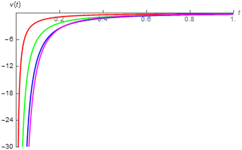
Figure 2. v(t) of fractional order capacitor with Cα = 1 F∙sα−1 excited by i(t) = δ(t) vs. t (red:│α│ = 0.2, green: │α│ = 0.4, blue: │α│ = 0.6, and magenta: │α│ = 0.8).
Since it can be seen from Figure the impulse response of the fractional order inductor is asymptotically vanished, we obtain:
(13)
(13)
for the fractional order inductor excited by impulse function.
However, this is not the case for the fractional order capacitor which its impulse response can be asymptotically existed as can be seen from Figure . For this device, we have found that:
(14)
(14)
Thus it can be seen that the upper bound of of the fractional order capacitor which is given by
, is inversely proportional to Cα. Moreover, we can simulate
of the fractional order capacitor as depicted in Figure which shows that
approaches 0 and its upper bound which is given by 1 V in this scenario as we assume that I = 1 A and Cα = 1 F∙sα−1, as │α│ approaches 0 and 1 respectively.
By using our expression, the rate of change i.e. dv(t)/dt, of the impulse response of fractance device can be found as:
(15)
(15)
which shows that:
(16)
(16)
Therefore it can be seen that the fractional order inductor with higher Lα and capacitor with lower Cα give the impulse response that progresses faster thus employs faster dynamic.
Finally, if the fractance device is excited by an impulse signal with arbitrary delay, td where td ≥ 0 i.e. i(t) = Iδ(t − td), we have the following expression for the response to such delayed impulse
(17)
(17)
Now, the expressions of responses to the step, ramp and parabolic input will be derived. These non-periodic functions which have been considered as they are the often cited test signals, can be generally given by(18)
(18)
where u() stands for the unit step function and {r} = {0, 1, 2}. It can be seen that (18) represents a step, ramp and parabolic input if we let r be 0, 1 and 2 respectively. By using (10) and (18), the general expression of the step, ramp and parabolic response can be given by:
(19)
(19)
Since Г(r + 1) = rГ(r), this general expression can be further simplified as:
(20)
(20)
By using our general expression i.e. (20), the expression for the response of the fractance device to a step, ramp and parabolic function can be determined by simply letting r be 0, 1 and 2. As an illustration, the expression for the step response can be obtained by letting r = 0 in the general expression as follows:
(21)
(21)
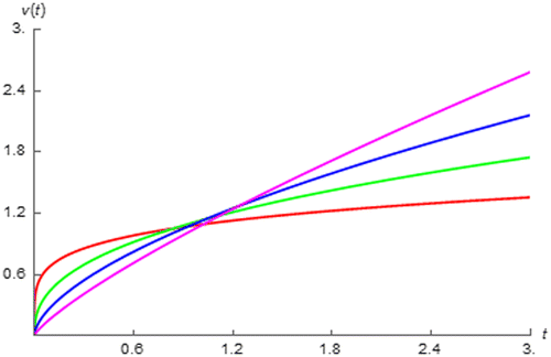
The step response is of particular interested because the causal DC stimulus which is often cited in electrical and electronic engineering can be mathematically modelled by using the step function. If we also assume that I = 1 A, Lα = 1 H∙sα−1 and Cα = 1 F∙sα−1, the step responses of the fractional order inductor and capacitor can be simulated by using (21) as respectively depicted in Figures and which show that the step response of the fractional order inductor and that of the fractional order capacitor is a time decreasing and increasing function. Figure also shows the fractional order inductor with │α│approaches 0 and 1 gives that step response that behaves more closely to a step and an impulse function. On the other hand, Figure shows that the fractional order capacitor give the step response that become more likely to a step and ramp function as│α│approaches 0 and 1. This confirms us that the fractance device with │α│approaches 0 behaves more likely to a resistor where the device with │α│approaches 1 behaves more like either an integer inductor if it is a fractional order inductor or an integer capacitor if it is a fractional order capacitor. From Figure , it can be seen that the step response of the fractional order inductor is asymptotically existed only for some values of │α│. Therefore we have found that:
Figure 4. v(t) of fractional order inductor with Lα = 1 H∙sα−1 excited by i(t) = u(t) vs. t (red:│α│ = 0.15, green: │α│ = 0.35, blue: │α│ = 0.55, and magenta: │α│ = 0.75).
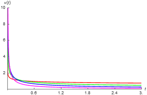
Figure 5. v(t) of fractional order capacitor with Cα = 1 F∙sα−1 excited by i(t) = u(t) vs. t (red:│α│ = 0.2, green: │α│ = 0.4, blue: │α│ = 0.6, and magenta: │α│ = 0.8).
(22)
(22)
which means that the upper bound of of the fractional order inductor i.e. LαI, is directly proportional to Lα. For the fractional order capacitor on the other hand, it can be seen from Figure that its step response is asymptotically existed for all values of│α│. Thus we have:
(23)
(23)
which shows that the lower bound of of the fractional order capacitor i.e.
, is inversely proportional to Cα. As a final remark from Figures and , it has been found that the fractance device with │α│approaches 0 responses to the step input thus to the causal DC stimulus faster than that with│α│approaches 1.
By also using (21), it has been found that dv(t)/dt of the step response when t > 0 can be given by the right hand side of (12). Therefore it can be seen from Figure that the fractional order inductor with│α│approaches 1 gives the step response with faster rate of change especially during transient. On the other hand, the fractional order capacitor with │α│approaches 0 gives the step response with faster and slower rate of change at initial and asymptotic respectively as can be seen from Figure . It can also be seen from the right hand side of (12) that for the step response as well as the impulse response. Therefore the fractional order inductor with larger size gives the step response thus the DC response that progresses faster where the opposite relationship can be seen from the fractional order capacitor.
By using (22) and (23), ’s of the fractional order inductor and capacitor excited by step input can be simulated by also assuming that I = 1 A, Lα = 1 H∙sα−1 and Cα = 1 F∙sα−1 as depicted in Figures and . These figures shows that
of the fractional order inductor which has LαI = 1 V under the assumed simulating condition, is a decreasing function of │α│. On the other hand,
of the fractional order capacitor approaches
which is given by 1 V in this case, as │α│ approaches 0.
Finally, if the fractance device is excited by a delayed excitation i.e. i(t) = I(t − td)ru(t − td) where r is given by 0, 1 and 2 if such excitation is a delayed step, ramp and parabolic input, td must be introduced to (20). Therefore we have the following general expression for delayed response.
(24)
(24)
5.2. The expressions for trigonometric and arbitrary periodic responses
In order to derive the expressions for trigonometric responses, both sinusoidal and cosinusoidal function have been considered as these functions are the typical mathematical models of the AC stimulus. Instead of the zero phase sinusoidal and cosinusoidal input assumed in the previous works (Elwakil, Citation2010; Krishna et al., Citation2008; Radwan & Elwakil, Citation2012a), a sinusoidal and cosinusoidal excitation with arbitrary magnitude, I and phase ϕ i.e.(25)
(25)
(26)
(26)
have been chosen due to their generality.
For saving the computational effort, we firstly determine the expression for the fractance device’s response to i(t) = I exp [j(ωt + φ)] then taking the real part and imaginary part of the result in order to obtain our desired expressions. This methodology can give our desired expressions becauseexp [j(ωt + φ)] = cos (ωt + φ) + j sin (ωt + φ). By using this methodology instead of them separately, the expressions of both sinusoidal and cosinusoidal responses can be simultaneously obtained within a single fractional differentiation thus saving the computational effort. With i(t) = I exp [j(ωt + φ)], the following fractance device’s response which is complex valued as the excitation is, can be obtained by using (10).(27)
(27)
Therefore the expressions of the cosinusoidal and sinusoidal response, can be obtained by taking the real and imaginary part of (27) as follows:(28)
(28)
(29)
(29)
It should be mentioned here that:
(30)
(30)
(31)
(31)
(32)
(32)
where 1F2(a1; b1, b2; z) is a generalized hypergeometric function with p = 1 and q = 2 (Dwork, Citation1990). This function can be defined for arbitrary p and q as:(33)
(33)
where (ai)n and (bj)n are Pochhammer symbols which can be respectively defined as:
(34)
(34)
(35)
(35)
Let {m} = {0, 1, 2, 3, …}. If φ = ± mπ rad, the expression of the cosinusoidal response can be simplified as (36)
(36)
and the expressions of the sinusoidal response can be reduced to:
(37)
(37)
It should be reminded here that K = Lα and K = 1/Cα for the fractional order inductor and capacitor.
At this point, it can be seen that our expressions for the trigonometric responses i.e. (28), (29), (36) and (37), are in terms of the generalized hypergeometric functions with p < q thus they are analytic everywhere (Willis, Citation2012), unlike cosα() and sinα(). If we let I = 1 A, ω = 200π rad∙s−1 and ϕ = 0.25π rad, the cosinusoidal and sinusoidal response of the fractional order capacitor and inductor due can be numerically simulated by using our expressions under the assumption that Cα = 1 F∙sα−1 and Lα = 1 H∙sα−1 as depicted in Figures – which display none of any singular point. They also show that the magnitudes of the responses of the fractional order capacitor have been much attenuated from that of the excitation where those of the fractional order inductors have been much amplified. This suggests us that the fractional order capacitor and inductor should be applied for the attenuation and amplification of the AC signal. Moreover, the fractional order inductor with │α│ approaches 1 gives larger │v(t)│ where the opposite relationship can be obtained from the fractional order capacitor.
Figure 8. v(t) of a fractional order capacitor with Cα = 1 F∙sα−1 excited by i(t) = cos (200πt + 0.25π) vs. t (red:│α│ = 0.4, green: │α│ = 0.5, and blue: │α│ = 0.6).
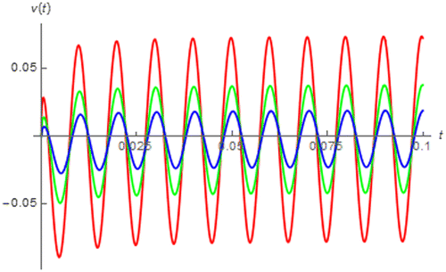
Figure 9. v(t) of a fractional order inductor with Lα = 1 H∙sα−1 excited by i(t) = cos(200πt + 0.25π) vs. t (red:│α│ = 0.4, green: │α│ = 0.5, and blue: │α│ = 0.6).
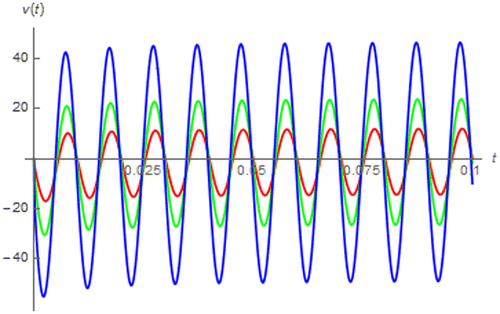
Figure 10. v(t) of a fractional order capacitor with Cα = 1 F∙sα−1 excited by i(t) = sin(200πt + 0.25π) vs. t (red:│α│ = 0.4, green: │α│ = 0.5, and blue: │α│ = 0.6).
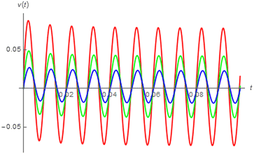
Figure 11. v(t) of a fractional order inductor with Lα = 1 H∙sα−1 excited by i(t) = sin(200πt + 0.25π) vs. t (red:│α│ = 0.4, green: │α│ = 0.5, and blue: │α│ = 0.6).
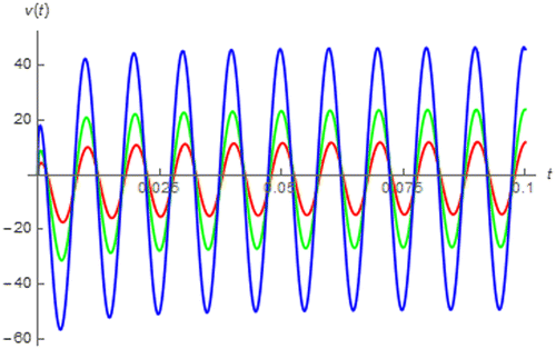
These figures also show that both sinusoidal and cosinusoidal response of the fractance device are asymptotically converged to the usual sinusoidal and cosinusoidal function which confirms us that the fractance device is linear time invariant. Since the magnitude and phase of the fractance device’s impedance function can be respectively given by Kωα and απ/2, we have the following expressions for the asymptotic cosinusoidal and sinusoidal response:
(38)
(38)
(39)
(39)
Since ω ≥ 0, it can be seen from (38) and (39) that the magnitudes of these asymptotic responses are increased with respected to α and K. On the other hand, the amount of phase shifting from the input is increased with respected to │α│. As the asymptotic responses can be now determined, the transient responses of the fractace device i.e. vtrans(t), due to both cosinusoidal and sinusoidal input can be obtained by using the following equation.
(40)
(40)
and can be simulated for both fractional order capacitor and inductor by using our expressions under the assumption that I = 1 A, ω = 200π rad∙s−1 and ϕ = 0.25π rad as shown in Figures –.
Figure 12. vtrans(t) of fractional order capacitor with Cα = 1 F∙sα−1 excited by i(t) = cos(200πt + 0.25π) vs. t (red:│α│ = 0.25, green: │α│ = 0.45, blue:│α│ = 0.65, and magenta:│α│ = 0.85).
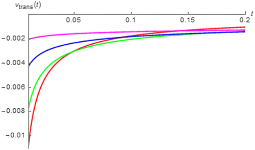
Figure 13. vtrans(t) of fractional order inductor with Lα = 1 H∙sα−1 excited by i(t) = cos(200πt + 0.25π) vs. t (red:│α│ = 0.15, green:│α│ = 0.35, blue:│α│ = 0.55, and magenta:│α│ = 0.75).
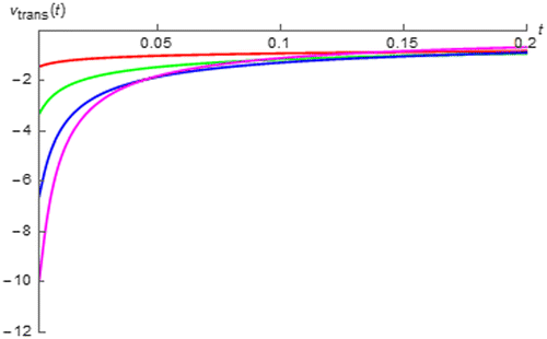
Figure 14. vtrans(t) of fractional order capacitor with Cα = 1 F∙sα−1 excited by i(t) = sin(200πt + 0.25π) vs. t (red:│α│ = 0.25, green: │α│ = 0.45, blue:│α│ = 0.65, and magenta:│α│ = 0.85).
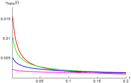
Figure 15. vtrans(t) of fractional order inductor with Lα = 1 H∙sα−1 excited by i(t) = sin(200πt + 0.25π) vs. t (red:│α│ = 0.15, green:│α│ = 0.35, blue:│α│ = 0.55, and magenta:│α│ = 0.75).
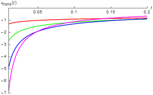
It can be seen from these figures that the transient cosinusoidal and sinusoidal responses of the fractional order capacitor and inductor which are of the same and opposite polarity, are asymptotically died out as expected and│vtrans(t)│of the fractional order capacitor as t approaches 0 is a decreasing function of │α│. On the other hand, the opposite relationships can be obtained from the fractional order inductor. Moreover, it can also be seen that the decaying rate of the transient response of the fractional order capacitor and that of fractional order inductor are respectively decreasing and increasing function of │α│ where obviously low decaying rate can be observed for the fractional order capacitor with│α│approaches 1 and inductor with│α│ approaches 0. This can be quantitatively confirmed by considering tC which is an amount of time required for │vtrans(t)│being decayed to 36.8% of its initial value i.e.│vtrans(tC)│ is approximately 36.8% of │vtrans(t)│ as t approaches 0. By using the data obtained from Figures and , tC for the cosinusoidal responses can be numerically determined for the fractional order capacitor and inductor as tabulated in Tables and . On the other hand, by using the data from Figures and , tC for the sinusoidal responses can be numerically calculated for the fractional order capacitor and inductor as given in Tables and .
Table 1. tC of the fractional order capacitor with Cα = 1 F∙sα−1 excited by i(t) = cos(200πt + 0.25π)
Table 2. tC of the fractional order inductor with Lα = 1 H∙sα−1 excited by i(t) = cos(200πt + 0.25π)
Table 3. tC of the fractional order capacitor with Cα = 1 F∙sα−1 excited by i(t) = sin(200πt + 0.25π)
Table 4. tC of the fractional order inductor with Lα = 1 H∙sα−1 excited by i(t) = sin(200πt + 0.25π)
From these tables, it can be seen that tC is respectively increased and decreased with respected to│α│for the fractional order capacitor and inductor where obviously high tC can be obtained for the fractional order capacitor with │α│approaches 1 and inductor with │α│ approaches 0. Since tC is inversely proportional to the decaying rate due to its definition mentioned above, the numerically obtained relationships between tC and│α│confirms the graphically obtained relationships between decaying rates and│α│. From these relationships, it can be summarized that the fractional order capacitor with│α│approaches 0 gives the the AC response that enters its steady state faster than that obtained from the device with│α│approaches 1 and the opposite relationship can be seen from the fractional order inductor.
Before we proceed to the subsequent section, it should be mentioned here that our expression for the sinusoidal response can be extensively used for deriving the expression for arbitrary periodic response. In order to do so, the Fourier’s theorem must be applied. According to such theorem, an arbitrary periodic input with period T, it can be alternatively given as a series of sinusoidal function as
(41)
(41)
where ω = 1/T. Moreover, In and ϕn stand for the magnitude and phase of arbitrary nth sinusoidal term of the series. By using (41) and our expression for sinusoidal response, the expression for arbitrary periodic response can be obtained in terms of the everywhere analytic generalized hypergeometric functions as follows:
(42)
(42)
where:
(43)
(43)
6. The applications to any subject that can be modelled with the fractance device
For the demonstrations, the applications of our expressions to the supercapacitors, lossy magnetic core inductive coils and Li-ion battery will be presented.
6.1. Supercapacitors
Since the supercapacitor behaves like a fractional order capacitor with resistive loss, it can be simply modeled as an internal resistance, R0 connects in series to a fractional order capacitor, Cα (Freeborn et al., Citation2013). Thus its voltage current relationship can be given by:
(44)
(44)
where V0 is the initial voltage of supercapacitor and −1 < α < 0 as the fractance device under consideration is of the capacitive type.
Let the supercapacitor be charged by the galvanostatic charging methodology which the device is supplied by a causal DC input current. Since such input current is mathematically a step function i.e. i(t) = Iu(t), v(t) of the supercapacitor can be given by using our expression for step response with K = 1/Cα as the capacitive device has been considered as follows:
(45)
(45)
If three commercial 1.5 F rated supercapacitors i.e. Panasonic EEC-S5R115, Elna DB-R5RD155T and Cooper Bussman KR-R5RV155-R (Freeborn et al., Citation2013), are of interested, their v(t)’s due to a 0.5 A charging current can be simulated by using (45) with I = 0.5 A and their parameters (Freeborn et al., Citation2013) shown in Table under the assumption that V0 = 0 V, as depicted in Figure where strong resemblances between our expression based v(t)’s to those experimentally collected step responses of various commercial supercapacitors (Freeborn et al., Citation2013) can be observed. It can also be seen that the charging rates of these supercapacitors are initially fast and become asymptotically slower where the Elna DB-R5RD155T employs the fastest charging rate followed by Panasonic EEC-S5R115 and Cooper Bussman KR-R5RV155-R respectively.
Table 5. Parameters of the 1.5 F rated supercapacitors (Freeborn et al., Citation2013)
Figure 16. v(t)’s due to a 0.5 A charging current of three commercial 1.5 F rated supercapacitor (red: Panasonic, green: Elna, and blue: Cooper Bussman).
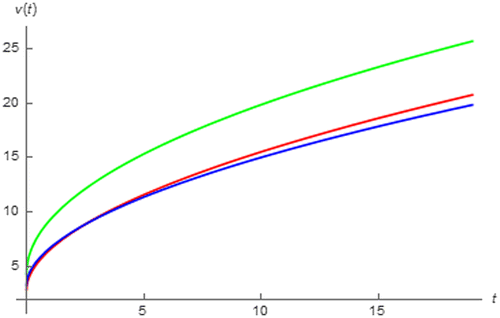
From (45), it can be seen that:
(46)
(46)
which indicates that the charging rate of any supercapacitor is inversely proportional to Cα. Therefore Elna DB-R5RD155T and Cooper Bussman KR-R5RV155-R employ the fastest and slowest charging rate due to their minimum and maximum Cα.
As v(t) is now determined, the instantaneous power, p(t) delivered to the supercapacitor can be immediately obtained for t ≥ 0 as follows:
(47)
(47)
Since R0 is not an energy storage element, I2R0 is a power loss according to IR0 voltage loss. According to R0’s shown in Table , it can be seen that Elna DB-R5RD155T has maximum loss followed by Cooper Bussman KR-R5RV155-R and Panasonic EEC-S5R115 respectively.
When the supercapacitor is discharging on the other hand, there is no input current. Therefore it can be modelled as a source free resistor-fractional order capacitor circuit. As a result, v(t) can be now given by assuming that the supercapacitor is now connected to the resistive load, RL as follows:
(48)
(48)
where t > tS which the supercapacitor is switched from charging to discharging mode assuming that the charging has been started at t = 0, and E-α[ ] is a single parameter Mittag-Leffler function (Valério et al., Citation2013). By using (45) and keeping in mind that R0 is not an energy storage element, VS can be mathematically defined as:
(49)
(49)
If we let V0 = 0 V, I = 0.5 A, tS = 19 s, and RL = 1 Ω, the discharging voltages of our three candidate commercial 1.5 F rated supercapacitors can be simulated as depicted in Figure where the horizontal axis is t-tS. This figure reveals that the Panasonic EEC-S5R115 supply maximum discharging voltage at initial followed by Cooper Bussman KR-R5RV155-R and Elna DB-R5RD155T. However, it can be seen that Elna DB-R5RD155T gives maximum discharging voltage at asymptotic. This figure also shows that the discharging rate is initially fast and asymptotically slow where Panasonic EEC-S5R115 employs the fastest rate followed by Cooper Bussman KR-R5RV155-R and Elna DB-R5RD155T. Since Elna DB-R5RD155T has a slowest discharging rate, it retains its initial voltage which is not significantly lower than those of the other supercapacitors, for a maximum proportion. Therefore it supplies the maximum discharging voltage at asymptotic.
Figure 17. v(t)’s at discharging states of three commercial 1.5 F rated supercapacitor (red: Panasonic, green: Elna, and blue: Cooper Bussman).
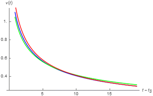
By using (48), it has been found that:
(50)
(50)
where E-α,0[ ] is a double parameters Mittag-Leffler function (Valério et al., Citation2013). It can be seen from (50) that the discharging rate inversely proportional to t thus it is initially high and become lower at asymptotic as observed. Moreover, (50) also shows that the discharging rate is an increasing function of│α│according to the property of the Mittag-Leffler function. Thus the Panasonic EEC-S5R115 and Elna DB-R5RD155T employ the fastest and slowest discharging according to their maximum and minimum │α│ as can be seen from Table .
As it has been assumed that the supercapacitor is connected to RL, the voltage drop across RL is equal to the supercapacitor’s discharging voltage given by (48). Therefore the discharging current of the supercapacitor which flows through RL, can be obtained by using (48) as:
(51)
(51)
As a result, p(t) supplied by the supercapacitor can be now given by using (48) and (51) as follows:
(52)
(52)
From (48) and (52), it has been found that p(t) = v2(t)/RL. Therefore it can be deduced from Figure that Panasonic EEC-S5R115 supply maximum power at initial where Elna DB-R5RD155T gives maximum power at asymptotic.
6.2. Lossy magnetic core inductive coil
Since this subject behaves as a lossy fractional order inductor, it can be simply modeled as an ohmic resistance of the conductor, RCu connects to a fractional order inductor, Lα in a series fashioned (Schäfer & Krüger, Citation2006). Thus its voltage current relationship can be given by:
(53)
(53)
where 0 < α < 1 as the device under consideration is inductive. If the sinusoidal response of the coil is of interest, it can be given by using (53) as follows:
(54)
(54)
where:
(55)
(55)
(56)
(56)
It can be seen that which is caused by RCu, is a usual sinusoidal function where
which is caused by Lα, is a fractional order inductor sinusoidal response and can be obtained by using our expression.
For the lossy magnetic core inductive coil of the Ferrite core and soft-iron core type i.e. the Ferrite core and soft-iron core inductive coil along with the loudspeaker coil which is also a lossy magnetic core inductive coil, their v(t)’s, ’s and
’s can be simulated by using (54)–(56) and their parameters (Schäfer & Krüger, Citation2006) shown in Table under the assumption that I = 1 A, ω = 200π rad∙s−1 and ϕ = 0.25π rad as depicted in Figures – where it can be seen from Figure that v(t) of Ferrite core inductive coil is almost similar to a normal sinusoidal function. This is because
is the major part of v(t) and
is almost identical to that of the ordinary inductor as │α│of this lossy inductive coil is very closed to 1.
Table 6. Parameters of the lossy magnetic core inductive coils (Schäfer & Krüger, Citation2006)
Figure 18. v(t) (blues), vLα(t) (red) and vRCu(t) (green) of the Ferrite core inductive coil due to i(t) = sin(200πt + 0.25π).
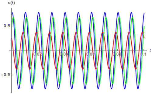
Figure 19. v(t) (blues), vLα(t) (red) and vRCu(t) (green) of the soft-iron core inductive coil due to i(t) = sin(200πt + 0.25π).
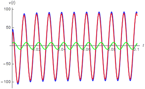
Figure 20. v(t) (blues), vLα(t) (red) and vRCu(t) (green) of the loudspeaker coil due to i(t) = sin(200πt + 0.25π).
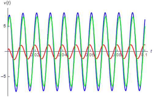
From Figures and , it can be seen that the soft-iron core inductive coil yields v(t) which is more similar to the fractional order inductor’s sinusoidal response than that of the loudspeaker coil even though │α│ of the loudspeaker coil is more closed to 1. This is because v(t) of the soft iron core inductive coil is dominated by its where that of the loudspeaker coil is dominated by its
. The reason for this is that the soft iron core inductive coil has considerably large Lα compared to its RCu unlike the loudspeaker coil.
Moreover, it can be seen from Figures – that is asymptotically converged to a usual sinusoidal function. This is not surprising as
is the fractional order inductor’s sinusoidal response. Therefore, we have:
(57)
(57)
which shows that the Ferrite core inductive coil yields the maximum amount of phase different between v(t) and i(t) and maximum degree of frequency dependent in amplitude followed by the soft-iron core inductive coil and loudspeaker coil according to their α’s.
By subtracting from
,
at transient i.e.
, can be obtained and numerically simulated for our lossy magnetic core inductive coils as depicted in Figures – where it can be seen that
is died out at asymptotic as expected. It can also be seen that
of the ferrite core inductive coil is very small thus it can be neglected in practice.
Moreover, it has been found by analyzing the data obtained from Figures – that the corresponding tC of , is given by 0.04855, 0.06588 and 0.08608 s for the Ferrite core inductive coil, soft-iron core inductive coil and loudspeaker coil respectively. Therefore it can be implied that
of the Ferrite core inductive coil has the maximum decaying rate due to its minimum tC followed by that of the soft-iron core inductive coil and loudspeaker coil. This is because the Ferrite core inductive coil has maximum│α│followed by the soft-iron core inductive coil and loudspeaker coil. This outcome is agreed with our transient behavioral analysis of the fractional order inductor excited by sinusoidal input given in Section 6.1.
Finally, as is asymptotically converged to a usual sinusoidal function, so does v(t). By using (54), (55) and (57) we obtain:
(58)
(58)
6.3. Lithium-ion battery
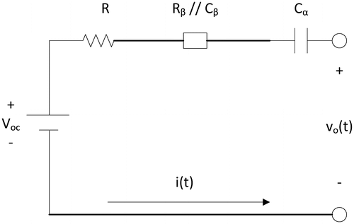
According to (Ma et al., Citation2016), the behavioral modeling of Lithium-ion battery can be achieved by using the fractional order circuit as depicted in Figure where Cα, Voc and vo(t) are respectively the fractional order capacitor with order α, the open circuit voltage and the battery terminal voltage respectively. Moreover, Rβ//Cβ denotes the parallel combination of resistor, Rβ and fractional order capacitor with order β, Cβ. Obviously, −1 < α < 0 and −1 < β < 0 in this scenario. From Figure , vo(t) can be related to i(t) by the following equation:
Figure 24. The fractional order circuit based behavioral model of Lithium-ion battery (Ma et al., Citation2016).
(59)
(59)
where vα(t) and vβ(t) denote the voltage dropped across Cα and that drop across Rβ//Cβ thus across Cβ.
Noted that vα(t) can be simply given by:(60)
(60)
Moreover, by keeping in mind that, vβ(t) can found as:
(61)
(61)
Therefore we obtain the following relationship between vo(t) and i(t):
(62)
(62)
Apart from using the electrical impedance spectroscopy (EIS) method (Barsoukov & Macdonald, Citation2005), Lithium-ion battery can be characterized by applying input with certainly known profile e.g. Economic Commission for Europe (ECE) 15 urban driving cycle which is used when the battery is applied in the electric vehicle (Ma et al., Citation2016) etc. Since such input is generally composed of many charging/discharging pulses (Ma et al., Citation2016), it can be mathematically given in terms of delayed step functions as:
(63)
(63)
where Ij, tj and tj+1 are the amplitude, beginning time and ending time of arbitrary jth pulse respectively. Noted also that tj < tj+1.
After substituting (63) into (62) and applying our expressions of delayed impulse and step response, the following vo(t) can be obtained:
(64)
(64)
Moreover, when tj < t < tj+1, the battery is subjected only to the jth pulse thus we have:(65)
(65)
As a result, vo(t) for tj < t < tj+1 can be obtained by using our expression for step response as follows:
(66)
(66)
where vo(tj) is the initial value of vo(t) according to the previous adjacent pulse.
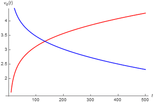
If we let the battery be subjected to 1.5 A pulse current with 500 s duration, vo(t) can be simulated by using (66) and the extracted parameters of Lithium-ion battery (Ma et al., Citation2016) as a redline depicted in Figure which shows that the battery is charging. In the same figure, vo(t) due to a −1.5 A pulse current of the same duration has also been simulated as a blue line where a discharging can be observed. Therefore it can be seen that the battery can be in either charging or discharging state depending on the polarity of Ij where the positive polarity yields charging and vice versa.
Figure 25. vo(t) of the Lithium-ion battery subjected to a 1.5 A pulse with 500 s duration (red) and a −1.5 A pulse with 500 s duration (blue) pulse current.
Moreover, the voltage drop across Cα i.e. vα(t), and vβ(t) when tj < t < tj+1 can be obtained by using (59) and (66) as:(67)
(67)
(68)
(68)
where vα(tj) and vβ(tj) stand for the initial value of vα(t) and vβ(t) due to the previous adjacent pulse respectively.
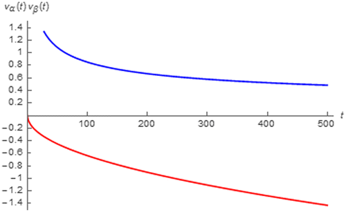
By using (67) and (68), vα(t) and vβ(t) during the charging and discharging process can be simulated in the similar manners to vo(t) as depicted in Figures and . These figures show that Cβ disrupts both charging and discharging process as vβ(t) < 0 and vβ(t) > 0 while charging and discharging which vo(t) must be respectively increased and decreased. Fortunately, the disruption is asymptotically reduced as │vβ(t)│ is decreased. On the other hand, Cα augments both charging and discharging process because vα(t) > 0 and vα(t) < 0 while charging and discharging where the increasing and decreasing in vo(t) is respectively expected. Moreover, such augmentation is increased with time as │vα(t)│ is a time increasing function.
Figure 26. vα(t) (red) and vβ(t) (blue) of the Lithium-ion battery subjected to a 1.5 A pulse with 500 s duration.
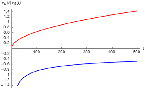
Figure 27. vα(t) (red) and vβ(t) (blue) of the Lithium-ion battery subjected to a −1.5 A pulse with 500 s duration.
Finally, the instantaneous power, po(t) and energy, Eo(t) either supply to the charging battery or delivered by the discharging one when tj < t < tj+1 can be obtained by using (65) and (68) as given by (69) and (70) respectively. These equations show that po(t) is nonlinearly time dependent and Eo(t) is a fractional order function of time. If both Cα and Cβ become the ordinary capacitors, po(t) and Eo(t) will respectively be linear and quadratic as both α and β become −1. Thus it can be seen that the nonlinearity of po(t) and fractional order time dependency of Eo(t) are caused by the influences of Cα and Cβ.(69)
(69)
(70)
(70)
7. Conclusion
In this work, novel expressions of time domain responses of fractance device excited by various renowned inputs e.g. impulse, step, ramp, parabolic, trigonometric and arbitrary periodic input etc., have been derived based on the Caputo fractional derivative. The dimensional consistency to the responses of the integer order devices have also been taken into account. The derived expressions have been found to be applicable to both fractional order inductor and capacitor with arbitrary α. They are also applicable to any subject that can be modeled with the fractance device where the applications to the supercapacitors, lossy magnetic core inductive coils and the Lithium-ion battery have been demonstrated. By using our expressions and numerical simulations with MATHEMATICA, the time domain behaviors of the fractional order inductor, fractional order capacitor, supercapacitors, lossy magnetic core inductive coils and the Lithium-ion battery have been thoroughly analyzed. So, this research has been found to be beneficial to those aforementioned fractance device related disciplines.
Acknowledgment
The author would like to acknowledge Mahidol University, Thailand, for the online database service.
Additional information
Funding
Notes on contributors
Rawid Banchuin
Rawid Banchuin received the BEng degree in electrical engineering from Mahidol University, Bangkok, Thailand in 2000, the degree of MEng in computer engineering and PhD in electrical, and computer engineering from King Mongkut’s University of Technology Thonburi, Bangkok, Thailand in 2003 and 2008, respectively.
He was with the Department of Electrical Engineering, Rajamangala Institute of Technology, North-Bangkok Campus since 2003. At present, he is with the Faculty Engineering, Siam University, Bangkok, Thailand.
Rawid Banchuin, an assistant professor, is a member of council of engineer (Thailand) and has joined the organizing committee of the international conference on ICT and knowledge engineering which is jointly organized by IEEE, since 2012. His current research interests include fractance device, fractional order circuits/systems, and deeply scaled semiconductor technology.
References
- Ahmad, W., El-khazali, R., & Elwakil, A. S. (2001). Fractional-order Wien-bridge oscillator. Electronics Letters, 37, 1110–1112. doi:10.1049/el:20010756
- Atangana, A., & Secer, A. (2013, April). A note on fractional order derivatives and table of fractional derivatives of some special functions. In Abstract and applied analysis (Vol. 2013). Hindawi. doi: 10.1155/2013/279681
- Banchuin, R., & Chaisricharoen, R. (2015, June). A generic analytical model of fractance response in time domain. In 2015 12th International Conference on Electrical Engineering/Electronics, Computer, Telecommunications and Information Technology (ECTI-CON) (pp. 1–4). IEEE. doi: 10.1109/ECTICon.2015.7207137
- Barsoukov, E., & Macdonald, J. R. (Eds.). (2005). Impedance spectroscopy: Theory, experiment, and applications. Hoboken, NJ: Wiley.
- Charef, A. (2006). Analogue realisation of fractional-order integrator, differentiator and fractional PIλDµ controller. IEE Proceedings-Control Theory and Applications, 153, 714–720. doi:10.1049/ip-cta:20050019
- Dorčák, Ľ., Terpák, J., Petráš, I., & Dorčáková, F. (2007). Electronic realization of the fractional-order systems. Acta Montanistica Slovaca, 12, 231–237. Retrieved from http://actamont.tuke.sk/
- Dwork, B. (1990). Generalized hypergeometric functions. Oxford: Clarendon Press.
- Elwakil, A. S. (2010). Fractional-order circuits and systems: An emerging interdisciplinary research area. IEEE Circuits and Systems Magazine, 10, 40–50. doi:10.1109/MCAS.2010.938637
- Elwakil, A. S., & Maundy, B. (2010). Extracting the Cole-Cole impedance model parameters without direct impedance measurement. Electronics Letters, 46, 1367–1368. doi:10.1049/el.2010.1924
- Freeborn, T. J., Maundy, B., & Elwakil, A. S. (2013). Measurement of Supercapacitor fractional-order model parameters from voltage-excited step response. IEEE Journal on Emerging and Selected Topics in Circuits and Systems, 3, 367–376. doi:10.1109/JETCAS.2013.2271433
- Gómez-Aguilar, J. F., Rosales-García, J. J., Bernal-Alvarado, J. J., Córdova-Fraga, T., & Guzmán-Cabrera, R. (2012). Fractional mechanical oscillators. Revista mexicana de física, 58, 348–352. Retrieved from http://rmf.smf.mx/
- Inaba, A., Manabe, T., Tsuji, H., & Iwamoto, T. (1995). Electrical impedance analysis of tissue properties associated with ethylene induction by electric currents in cucumber (Cucumis sativus L.) Fruit. Plant Physiology, 107, 199–205. Retrieved from http://www.plantphysiol.org/10.1104/pp.107.1.199
- Jesus, I. S., MacHado, J. T., & Cunha, J. B. (2008). Fractional electrical impedances in botanical elements. Journal of Vibration and Control, 14, 1389–1402. doi:10.1177/1077546307087442
- Jifeng, W., & Yuankai, L. (2005). Frequency domain analysis and applications for fractional-order control systems. Journal of physics: Conference series, 13, 268. doi:10.1088/1742-6596/13/1/063
- Krishna, B. T., Reddy, K. V. V. S., & Santa Kumari, S. (2008). Time domain response calculations of fractance device of order 1/2. Journal of Active and Passive Electronic Devices, 3, 355–367. Retrieved from http://www.oldcitypublishing.com/journals/japed-home/
- Ma, Y., Zhou, X., Li, B., & Chen, H. (2016). Fractional modeling and SOC estimation of lithium-ion battery. IEEE/CAA Journal of Automatica Sinica, 3, 281–287. doi:10.1109/JAS.2016.7508803
- Podlubny, I. (2002). Geometric and physical interpretation of fractional integration and fractional differentiation. Fractional Calculus & Applied Analysis, 5, 367–386. Retrieved from https://arxiv.org/pdf/math/0110241.pdf
- Radwan, A. G., & Elwakil, A. S. (2012a). An expression for the voltage response of a current-excited fractance device based on fractional-order trigonometric identities. International Journal of Circuit Theory and Applications, 40, 533–538. doi:10.1002/cta.760
- Radwan, A. G., & Elwakil, A. S. (2012b, November). Transient-time fractional-space trigonometry and application. In International Conference on Neural Information Processing (pp. 40–47). Springer Berlin Heidelberg. doi: 10.1007/978-3-642-34475-6_6
- Schäfer, I., & Krüger, K. (2006). Modelling of coils using fractional derivatives. Journal of Magnetism and Magnetic Materials, 307, 91–98. doi:10.1016/j.jmmm.2006.03.046
- Stanislavsky, A. A. (2005). Twist of fractional oscillations. Physica A: Statistical Mechanics and its Applications, 354, 101–110. doi:10.1016/j.physa.2005.02.033
- Tang, C., You, F., Cheng, G., Gao, D., Fu, F., & Dong, X. (2009). Modeling the frequency dependence of the electrical properties of the live human skull. Physiological Measurement, 30, 1293. doi:10.1088/0967-3334/30/12/001
- Valério, D., Trujillo, J. J., Rivero, M., Machado, J. T., & Baleanu, D. (2013). Fractional calculus: A survey of useful formulas. The European Physical Journal Special Topics, 222, 1827–1846. doi:10.1140/epjst/e2013-01967-y
- Vinagre, B. M., & Feliu, V. (2007). Optimal fractional controllers for rational order systems: A special case of the wiener-hopf spectral factorization method. IEEE Transactions on Automatic Control, 52, 2385–2389. doi:10.1109/TAC.2007.910728
- Willis, J. L. (2012). Acceleration of generalized hypergeometric functions through precise remainder asymptotics. Numerical Algorithms, 59, 447–485. doi:10.1007/s11075-011-9499-9

![Figure 3. limt→∞[v(t)] of fractional order capacitor with Cα = 1 F∙sα−1 excited by i(t) = δ(t) vs. │α│.](/cms/asset/8f3bd810-2b70-468d-a667-4b5cf0768a53/oaen_a_1320823_f0003_oc.gif)
![Figure 6. limt→∞[v(t)] of fractional order inductor with Lα = 1 H∙sα−1 excited by i(t) = u(t) vs. │α│.](/cms/asset/acd1e1b8-2860-4d20-a0ec-d8da2b898682/oaen_a_1320823_f0006_oc.gif)
![Figure 7. limt→∞[v(t)]of fractional order capacitor with Cα = 1 F∙sα−1 excited by i(t) = u(t) vs. │α│.](/cms/asset/2212e428-e2c6-4536-8813-ebf3d609b64b/oaen_a_1320823_f0007_oc.gif)
