 ?Mathematical formulae have been encoded as MathML and are displayed in this HTML version using MathJax in order to improve their display. Uncheck the box to turn MathJax off. This feature requires Javascript. Click on a formula to zoom.
Abstract
The heat pipe is a passive cooling device that transfers heat from a hot source to a heat sink using fluids as a working medium. Working medium evaporation and condensation are key factors for designing an efficient heat pipe. Many researchers highlight nanofluids, a mixture of base fluid and nanoparticles, as a new working medium for more efficient heat pipes. The present research aimed to investigate heat pipe long-term performance using water-based nanofluids as working medium. Nanofluids with 1 and 3 vol% Al2O3 of 20–70 nm particle diameter in water were prepared and characterized. It has been seen in our previous study that the heat pipe performance is enhanced by an average of 26%; however, this enhancement was not sustained over long use and raised a concern about the long-life homogeneity of the nanofluid due to the liquid evaporation. Therefore, we investigated used nanofluid characteristics to determine whether it stays suspended in the base fluid as dispersed particles, or it agglomerates, then aggregates in bigger sizes and then precipitates. The dried heat pipe’s porous medium is cut-out after several uses and is scanned by electron microscope (SEM) at different operation heat loads. Some aggregated nanoparticles have been seen on the wick surface, which caused a capillary and thermal resistance. Also, a sample of the used nanofluid is dried and scanned by SEM, and it shows similar particles aggregation to those observed on the surface of the porous medium. This study showed heat pipe performance improvement because of the heat transfer enhanced features of nanofluids technology, and it justifies the performance decay after long-term use.
Public Interest Statement
The heat pipe is a passive cooling device that transfers heat from a hot source to a heat sink using fluids as a working medium. The fluid phase-change increases the heat pipe thermal conductivity by more than ten times compared to solids. The present research investigated heat pipe using water-based nanofluids as working medium. Nanofluid is a homogeneous mixture of base-fluid and nanoparticles. The nanoparticles sizes are in the range of 20–70 nm diameter. In this study, water is used as a base-fluid, and alumina nanoparticles are dispersed in water with 1 and 3 vol%. Previous studies indicated that the heat pipe performance is enhanced by an average of 26%; however, this enhancement did not persist for long time use because of nanofluids structure deteriorating. Scanning Electron Microscope results for Heat pipe cutout showed aggregated nanoparticles on the wick surface, which increased the capillary and the thermal resistance.
1. Background and introduction
Heat pipe is a passive heat transfer device that works based on working medium (fluid) phase change to increase the device thermal conductivity compared to solids. Working fluid properties are of primary concern when designing a heat pipe (HP) device to dissipate heat with minor temperature drop. Working medium phase change behavior varies from one liquid to another, and its saturation temperature is altered by adding particles or solutes. Therefore, the working fluid’s thermophysical properties influence its thermal performance (Shafahi, Bianco, Vafai, & Manca, Citation2010). Unusual heat transfer improvement methods are required to cope with the required cooling demand in high-energy compact devices, such as computer processors and MEMS devices. All traditional liquids have low heat transfer properties with respect to the thermally conductive solids (Kang, Wei, Tsai, & Yang, Citation2006). A nanofluid is a mixture of base-liquid and solid particles made from highly thermal-conductive metals in nano-scale; nanoparticles must be dispersed in base-liquid in a homogeneous suspension pattern (Choi, Citation1995; Kakaç & Pramuanjaroenkij, Citation2009). Several studies have experimentally facilitated nanofluids such as HP working-medium incorporating solid metal nanoparticles such as silver, copper oxide, diamond, alumina, titanium, nickel oxide and gold (Kang, Wei, Tsai, & Huang, Citation2009; KyuHyung, HyoJun, & Seok, Citation2010; Lin, Kang, & Chen, Citation2008; Yang, Liu, & Zhao, Citation2008). The fabricated nanofluids acquired noticeably higher thermal conductivity and high heat transfer properties compared to the conventional pure liquid (Kang et al., Citation2006). Nanofluids’ thermophysical and rheology properties, phase saturation, specific heat, thermal conductivity, density, and viscosity are based on the nanoparticle’s types and concentrations (Kakaç & Pramuanjaroenkij, Citation2009). The HP size and design at different operation conditions using different nanoparticles metals in various base-liquids is investigated by other researchers (Asirvatham, Nimmagadda, & Wongwises, Citation2012; Kang et al., Citation2006) in parametric study. Alumina (Al2O3), silver (Ag) and copper oxide (CuO) are among the most utilized nanoparticles that are well investigated (Asirvatham et al., Citation2012; Hassan, Singh et al. Citation2015; Hung, Teng, & Lin, Citation2013; Kakaç & Pramuanjaroenkij, Citation2009; Kumar, Sridhar, & Narasimha, Citation2014; Lai, Phelan, Vinod, & Prasher, Citation2008; Lin et al., Citation2008; Moraveji & Razvarz, Citation2012; Nguyen, Roy, & Gauthier, Citation2007; Noie, Heris, Kahani, & Nowee, Citation2009). As proposed by Minkowycz, Sparrow, and Abraham (Citation2012), the thermal conductivity of base-liquid could increase by adding solid particles of diameters less than 100 nm indicating the importance of the nanoparticles size. The influence of the nanoparticles concentration on the heat pipe performance is considered by Shafahi et al. (Citation2010) using nanofluids that constituted the most common nanoparticles, and were able to optimize the mass concentration for nanoparticles to maximize the HP heat transfer. Water-gold nanofluids showed a significant reduction in the HP thermal resistance as investigated by Tsai et al. (Citation2004). 50–80% reduction in the thermal resistance is reported by Zhou (Citation2004), using particle sizes of 10 and 35 nm in water-copper nanofluids in a grooved HP evaporator. Another significant reduction in the HP thermal resistance, 76.2%, is reported by Asirvatham et al. (Citation2012) incorporating a water-silver nanofluid. Water-alumina nanofluids are included in HP by Hung et al. (Citation2013), KyuHyung et al. (Citation2010) and Noie et al. (Citation2009), and all showed significant improvement in the HP heat transfer rate, across a range of methodologies. However, the studies did not mention whether these improvements are repeatable or not. The water-silver nanofluid-filling ratio in the thermosyphon study by Paramatthanuwat, Boothaisong, Rittidech, and Booddachan (Citation2010) did not show an effect on the heat transfer properties; however, it affects the heat transfer rate. As concluded from the literature survey, heat pipe incorporating nanofluids with different particle materials, size and concentration are of interest to many researchers. However, it is a challenging device because of the complex physics of the working medium. There is a gap of published work concerning the stability of nanofluids after base-liquid separation due to phase change in heat pipe evaporator. Questions regarding the HP effectiveness reliability are still being answered unconvincingly, to the extent that it is not certain whether nanoparticles’ suspension stability will be sustainable in a given liquid medium over the device usage period. Do the particles stick to a given HP wall surface? Do particles agglomerate and/or aggregate due to base-liquid evaporation? Do particles block the porous medium and affect the wick capillarity (wettability)? To our knowledge, a gap of relevant studies explains the transient changes occurring between the heat pipe and nanofluid need to be fulfilled. Therefore, further experimental studies are required to investigate the effectiveness of the HP incorporating nanofluids’ temporal performance sustainability. Different nanoparticles concentrations with and without surfactants are critical factors to support the current understanding. The main objectives of this study are to investigate the heat pipe’s nanofluid-enhanced performance stability after one year of usage under the same operation conditions and to justify the redundant performance with the HP life performance reliability.
2. Nanofluids preparation and characterization
2.1. Particle size distribution
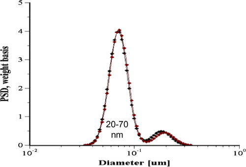
Water-alumina nanofluids with a volume concentration of 1 and 3% nanoparticles, 20–70 nm in diameters, are manufactured as explained in our previous publication (Hassan, Singh et al., Citation2015). Alumina nanoparticles are dispersed in deionized water, and the suspensions were sonicated in room temperature control facility, 25 ± 5°C using a high-performance dispersing instrument, IKA T25 digital ULTRA-TURRAX, for 6 h. The suspension was stabilized by acidifying with hydrochloric acid to a pH of 5.4, which is far from the isoelectric point (IEP) of alumina nanofluids. The particle diameter distribution and suspensions zeta potential were characterized by an acoustic and electroacoustic spectrometer from Dispersion Technology, DT-1201. Figure shows the particle size distribution (PSD) of alumina particles in the tested nanofluids, and it shows a binomial distribution of 20–70 nm with 65 nm peak value. This distribution is in reasonable agreement with the dry alumina particles manufacturer’s manual, although some deviation because of the wet environment versus the dry one is noticed. Some aggregates are represented by the presence of a small binomial-peak which is not in the original manufacturer’s particle size range; they are relatively very few in population to affect the fresh nanofluid thermophysical properties. This distribution infers that the nanoparticles are dominating the suspensions alone with few aggregates. However, it gives an indication of the possible aggregation if the particles are getting closer to each other due to liquid separation.
2.2. Nanofluids viscosity characterization
Rheology characterization of water-alumina nanofluids is measured from a stress-controlled ARES-G2 Rheometer using a 30 mm diameter bob setting for the concentric cylinder. Advanced Peltier Systems (APS) is used to control the system’s temperature with an accuracy of ± 0.1°C within the range of 20–60°C.
The experiment was conducted at 5.485 mm of a gap between bob and cylinder. Effective-viscosity (μeff), the viscosity of the nanofluids to that of the base fluid at same measuring conditions, versus shear rate measurements is carried over a wide range of 0.1 to 1,000 s−1 as shown in Figure . The shear rate is varied logarithmically to cover a broad range of viscosity measurements. The examined nanofluids showed a Newtonian behavior in the experimental range.
Figure 2. μeff versus shear rates of water-based nanofluids at 200°C (Hassan, Singh et al., Citation2015).
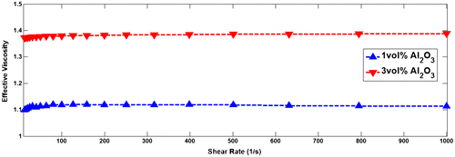
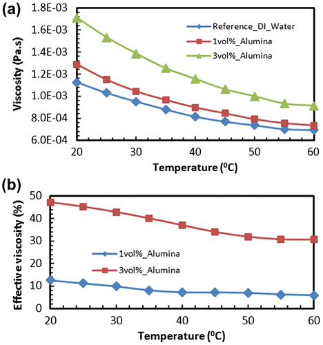
Figure (a) shows the rheology measurements for the nanofluids viscosity versus temperature at different alumina particles concentrations. The effective viscosity behavior of the nanofluids against temperature is shown in Figure (b). As indicated in Figure (a), the viscosity is exponentially decreased with temperature increase indicating an Arrhenius type trend for the nanofluids, which is in agreement with what had been seen by Zhou, Ni, and Funfschilling (Citation2010). Further, the effective viscosity’s temperature dependence can be seen to be more significant at 3 vol% as shown in Figure (b). This effect might infer that the contribution of intermolecular forces between particles to increase the nanofluid viscosity at a lower temperature and decays with increasing the energy of Brownian motions because of the temperature. Therefore, the rheology effect will be reduced by increasing the temperature. The lower particle concentration, 1%, comes closer to the base fluid viscosity; however, the higher particles concentration, 3%, still showing a significant difference in viscosity at high temperature. These results are indicating that the higher particle concentrations will be even getting worse.
2.3. Thermal conductivity measurements
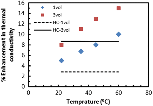
The methodology and technique that have been used for thermal conductivity measurement are discussed and detailed in Hassan, Singh et al. (Citation2015). Figure illustrates the thermal conductivity enhancement for the alumina particles nanofluids in the temperature range of 20 to 60°C. The percentage enhancement is calculated as the percentage change of the nanofluid thermal conductivity with respect to the base fluid. In this case, water was the base fluid with a thermal conductivity variation from 0.615 to 0.651 W/m K in the measured temperature range. The thermal conductivity improvement is much higher than that of the Hamilton Crosser (HC) model. In addition, nanofluids thermal conductivity improvement is strongly temperature dependent.
Figure 4. Percentage Enhancement in thermal conductivity versus temperature (Hassan, Singh et al., Citation2015).
2.4. Boiling and specific heat measurements
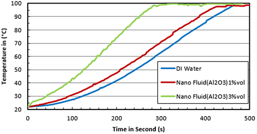
The aim of this test is to measure the thermal diffusion rate of the base fluid and the nanofluids under investigation as well as their specific heat and find out if there is any correlation between these two quantities. An experimental investigation for the γ-alumina nanofluids pool boiling heat transfer is done by Wen and Ding (Citation2005). The measurements showed significant enhancement in the boiling heat transfer; the enhancement reaches 40% at alumina particle (size 10–50 nm) loading of 1.25% by weight. A similar experiment for our in-house prepared nanofluids is performed at atmospheric pressure; however, the boiling heat transfer coefficient is out of the scope of this paper. A temperature controlled hot plate is implemented to warm-up the nanofluid to its boiling onset. A linear sensitivity thermocouple, E-Type, is centered in the nanofluid, and a data-acquisition device is used to acquire the temporal temperature readings, similar to T6 in Wen and Ding (Citation2005). An error analysis showed ±1.1°C uncertainty for this experiment setup with 95% confidence. Temperature versus time measurements for base-fluid as well as nanofluids at different particles concentration is shown in Figure . The main idea here is to fix the heat source rate, , and record the nanofluid’s temperature response versus time. As it can be seen from the plots, the temperature versus time curve slope
is elevated by introducing nanoparticles, and more elevation is shown by increasing nanoparticles’ concentration. These results indicate the enhancement in the boiling heat transfer coefficient as previously observed by Wen and Ding (Citation2005). Higher
depicts higher heat transfer rate according to Equation (4).
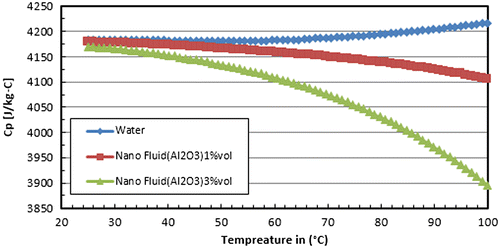
The nanofluid specific heat varies with the nanoparticle concentration in the base fluid according to Equation (1) as reported by Buongiorno (Citation2005). Figure shows the measured Base fluids (Cp) as well as the calculated nanofluid’s specific-heat, , versus temperature. Particle’s concentration,
, and nanofluid density,
, are calculated from Equation (3) (Pak & Cho, Citation1998). In contradiction to the base fluid, the specific heat of the nanofluid
is depreciated by elevation of temperature as well as the nanoparticles concentration as illustrated in Figure .
According to the heat diffusion rate equation, Equation (2), at constant heat rate, , and fixed fluid mass, the higher
slope will be faced with a specific heat reduction. Therefore, the results of Figures and are in good agreement as the heating curve slope (
) in Figure is increased by increasing the nanoparticles concentration, which in turn reduces the nanofluid specific heat. The learning outcome of this observation is concluded in the thermal diffusion enhancement of the nanofluids compared to the base fluid.
The measured average specific heat of these fluids are 4.14 ± 0.06 kJ/kg K for water, 4.04 ± 05 kJ/kg K for 1% nanofluids, and 3.8 ± 04 kJ/kg K for the 3% nanofluids. It can be seen that the predicted values are higher than the measured ones; however, this indicates the same trend for the three concentrations. One can say, the nanofluid heat conductive enhancement shown in Figure is associated with specific heat reduction; which depicts an additional appreciation effect toward nanofluids’ thermal diffusivity (α), .
(1)
(1)
(2)
(2)
(3)
(3)
As illustrated from the nanofluids characterization, significant heat transfer properties enhancement is observed and it is in compliance with previously published literature. The question here is whether these enhancements remain with time, when nanofluids’ phase change is mandatory in the implemented application. The heat pipe is one of these applications that have been developed based on working medium phase change phenomena. When nanofluid was applied in the heat pipe, it showed a significant conductivity enhancement as reported by Hassan, Singh et al. (Citation2015) in agreement with a number of publications. Later, on focusing on the phase change it is found that the heat pipe does not result in the same performance over a period of just several months. The study was repeated over a period of one year, and a comprehensive structural investigation is performed on the heat pipe internal surface as well as the used nanofluid. The following section will describe these study results.
3. Experimental apparatus
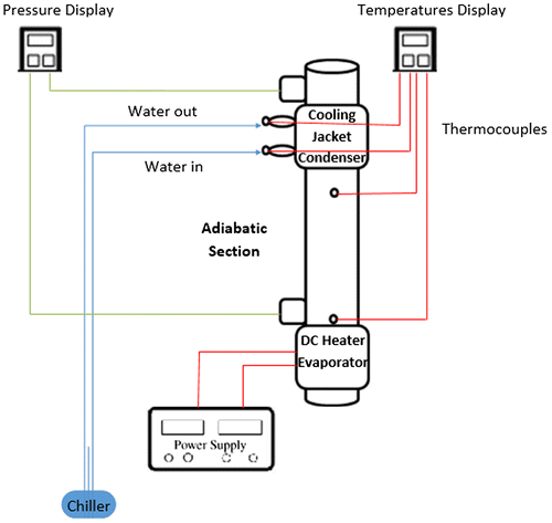
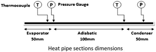
The apparatus is a modification of the design previously built by Hassan, Singh et al. (Citation2015) to facilitate the working medium recharging as illustrated in Figures and , wherein the HP internal diameter is 10 mm, and the total length is 200 mm. A 1 mm thick porous mesh is lining the pipe’s internal wall, 90% porosity porous medium. The evaporator section is surrounded by an electrical heater with adjustable power supply. AC and DC electric heaters are alternatively used as a heat source. AC-heater supplies 80 W of heat rate and the DC heater supplies 50 W of heat rate. A cold water jacket is used to dissipate the condenser heat. Vacuum-pressure (VP) sensors and E-Type thermocouples (TC) are inserted in the adiabatic and the condenser sections as shown in Figure . TC1 and TC2 for readings T1 and T2 are inserted 1 mm near the inside wall surface and 100 mm a part as demonstrated in Figure . Vacuum pump with rigid houses and needle valves are facilitated to affirm the vacuum tightness in the HP and to control its fluid recharging process. The heater power rate is used to control the evaporator temperature, T2. The vacuum pressure gauges are used to measure the vacuum level and to record the pressure development in the pipe due to the evaporator heat load.
4. Experimental analysis
Following the nanofluid preparation and characterization, it has been used to recharge the HP for a series of experimental runs for performance measurements. Fresh HP are used to comply with the fresh working medium. The vacuum pressure before every run is 750 mm Hg and the nanofluid charge is 10 ml. The evaporator temperature, T2, is a controlled variable, condenser temperature, T1, is a dependable variable. The first subsection of the experimental results will explain the heat pipe performance versus the evaporator temperature over one year of operation, and the second subsection will present and discuss the ANOVA SEM microscopy imaging for the nanoparticles structure in the heat pipe porous medium.
4.1. Heat pipe performance results and discussion
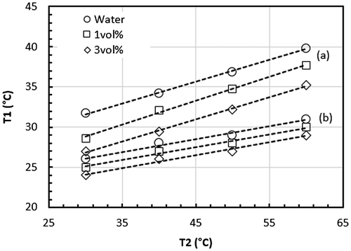
Heat flows in the HP through its metal skin and working medium phase change. Temperatures are measured across the adiabatic section of the HP metal skin using TC1 and TC2. The main idea of these measurements is to monitor the portion of heat transfers by each medium. If the temperature difference across the metal skin is increased, it indicates more heat is carried on by the phase change of the fluid medium, which can be used as an indicator for the HP thermal performance enhancement. The opposite, if the temperature difference is decreased, indicating that more heat is carried on by the HP metal skin, which indicates lower HP performance. Temperatures plots, T1 versus T2, for the three investigated working mediums, water and nanofluids 1 and 3 vol% are illustrated in Figure . There are two sets of plots in this figure, set (a) shows the three working medium plots results for the fresh HP (AC heater is used), and set (b) shows the corresponding results for the reused HP (DC heater is used). It can be seen from Figure that the fresh HP plots depict a significant effect for using nanofluids as a working medium compared to the reused HP. The heaters power rate is controlled by TC2, the heat rate in the condenser is controlled by varying the condenser cooling water flow rate. Therefore, as T2 varies, T1 is responding to this variation according to the HP thermal performance. According to Fourier equation, Equation (4), if the pipe cross-section area, A, the distance between the T2 and T1 thermocouples, dx and the HP metal thermal conductivity, k are constants, then the heat transfer rate, , will be directly proportional to the temperature difference as shown in Equation (5).
(4)
(4)
(5)
(5)
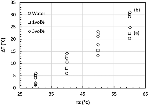
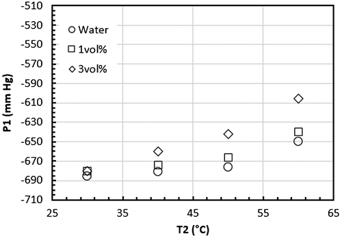
Therefore, the increase of the temperature difference between the two measured temperatures indicates more heat absorption by the working fluid rather than the skin thermal conductivity and vice versa, as is going to be explained by the HP pressure measurements in Figure later in this section. The temperature difference (T2 − T1) is calculated from temperature results in Figure and is plotted versus the control temperature, T2, as shown in Figure . As it can be seen in the figure, the temperature difference increases in the direction of the base fluid to the higher particles concentration nanofluids as an indication of enhancement in the HP thermal performance. It indicates the effectiveness of the nanofluids in increasing the heat pipe heat-transfer rate through the working medium thermal diffusion and evaporation as seen earlier in Hassan, Alzarooni et al. (Citation2015).
In order to get a better understanding of the effect of T2 and T1 readings, an increase in heat transfer rate relationship is derived from Equation (5) as shown in Equation (6) below.(6)
(6)
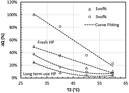
The enhancement in the heat pipe heat transfer, on the left-hand side of Equation (6), is calculated from the temperature difference results in Figure , on the right-hand side of the equation, for both fresh and long term used HP. The results are plotted in Figure versus the control temperature T2. It can be seen that the change is much higher than the uncertainty in these experiments, which was less than 5% with a confidence level of 95%. The thermal diffusivity improvement can also be seen from the vacuum pressure (VP) sensor readings, Figure . Initially, pressure sensor readings indicated higher-pressure for 3 vol% nanofluids, then later, and after several runs, no significant change has been noticed.
Figure illustrates the HP performance changes due to the long-term usage as represented by the significant reduction of the heat transfer rate, ΔQ. In addition, it shows the linear behavior of the HP performance reduction with increased evaporator temperature, T2 for the fresh HP versus the nonlinear behavior for the long-term used HP. The nonlinearity could be an indication for the particles’ accumulation on the HP porous medium.
Figure shows the HP pressure measurement versus the control temperature, T2 for the fresh HP with the tested nanofluids. The working medium evaporation enhancement can be seen in this figure as the pressure in the HP is increased by increasing the particles concentration in the nanofluid as well as T2. To sustain the pressure in the heat pipe at its initial value, more heat should be removed by the condenser cooling, indicating an enhancement in the heat transfer load that can be removed by the HP with nanofluids. This observation promotes the nanofluid to be an efficient working medium for HP cooling equipment. Therefore, with these results, nanofluids indicated a positive impact on the HP efficiency as it increases the temperature difference along the adiabatic section as shown in Figure for the fresh HP, and therefore increases the heat dissipation from the evaporator.
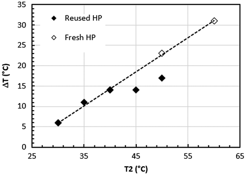
To draw a robust conclusion for the observed deficiency of the HP after long-term of usage and eliminate the doubt of the heater type effect (e.g. AC versus DC), the experiment has been repeated three months later for the HP with the DC heater. An unpredictable performance is observed as seen in Figure for the high nanoparticles’ concentration fluid. As shown, with the 3 vol% working medium deteriorating, it has a significant temperature difference drop compared to the less used HP, with T2 between 45 and 55°C. The reason is mainly because of the base fluid separation which occurs while the working medium is evaporated in the evaporator.
In order to explain this observation, the case of water desalination process is a good example. In this process, pure water is separated from saline water (water + salt) leaving more salt concentrated brine with different thermal properties. Similarly, in the nanofluid, water will be separated in the evaporator leaving higher nanoparticles concentration fluid behind. When the condensate is returned to the evaporator, it will not be mixed perfectly as it was sonicated in the preparation process. Therefore, nanofluid homogeneity and stability are altered and two new separate working mediums are generated in the HP evaporator: pure water and highly concentrated nanofluid. This will definitely impact the forces and the bridging balance mechanisms between the particles and liquid. Particles agglomeration followed by aggregation would be the results of this mechanism imbalance. Microscopic imaging is presented in Section 4.2 for the HP wick as well as the nanoparticles after several uses are investigated to prove the above discussion.
4.2. ANOVA scan electron microscopy (SEM) results and discussion
SEM imaging is performed for the HP internal mesh and for the dried nanoparticles that are collected from fresh and reused nanofluids.
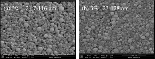
Figures shows and SEM images for the HP internal mesh for the 3 vol% nanofluids when it is fresh (a) and after one month of use (b). The images indicate a significant increase in the nanoparticles coat layer on the mesh surface after one month of use in the HP. Dried particles SEM images are shown in Figure for the same nanofluid particles. By investigating the particle size range, it can be seen that the particle size is increased due to the particles agglomeration and aggregation as discussed in the previous section.
These images indicate a significant impact on the base fluid separation process that will not only increase the nanofluid particles concentration but also will increase the particle size. Accumulating the particles on the mesh may increase its wettability as mentioned in KyuHyung et al. (Citation2010); however, this may block the wick porosity if the wick’s mesh is not sufficiently coarse. Therefore, the HP performance enhancement that has been seen experimentally by KyuHyung et al. (Citation2010) and computationally by Mashaei, Shahryari, Fazeli, and Hosseinalipour (Citation2016) may not remain if the experiment is repeated several times and if the model implements the attractive forces between the particles when liquid is evaporated leaving the particles closer to each other.
5. Conclusions
This research aimed to investigate the long-term performance of heat pipe devices facilitated by nanofluids as working medium. Water-based nanofluids with 1 and 3% alumina particles are prepared using sonication process and are well characterized for particle distribution stability as well as for thermophysical properties. The heat pipe study was accomplished in 10 mm diameter copper HP lined by 1 mm brass mesh. The HP performance is measured using vacuum pressure sensors and thermocouples that are installed in the evaporator and condenser, separated by an adiabatic section. Pressure results indicated the vacuum pressure level in the pipe drops, as does the instantaneous pressure. The temperature measurements indicate a change in the heat transfer rate across the heat pipe at different operation conditions and different nanofluids particle concentration. Fresh and reused heat pipes are used for performance comparison. Heat pipe heat transfer rate is improved, with up to 100% change in the heat transfer rate. However, the improvement depreciates after reusing for several trials in a one year period. This decay raises a concern about the particles distribution and suspension sustainability after the base-fluid separation due to phase change. In order to determine whether it is particles agglomeration or aggregation, another set of experimental characterization has been done on the used nanofluid comparing with the fresh one. Scan electron microscope (SEM) imaging analyses are performed on the cutout internal surface of the heat pipe porous medium as well as the used nanofluid particles to investigate the nanoparticles structure. The SEM results revealed a noticeable increase in the nanoparticles size, with nanoparticles coating on the wick-mesh. Particle sizes elevation indicated particles agglomeration and aggregation, that definitively accounts for the development of a skin layer and porosity reduction leading to the heat pipe’s performance depreciation.
Funding
Masdar Institute of Science and Technology student and research grants are greatly acknowledged for completing this study.
Supplemental data
Supplemental data for this article can be accessed at http://dx.doi.org/10.1080/23311916.2017.1336070.
Acknowledgements
Technical language review is provided by Academic Writing Lecturer Kevin Garvey at Masdar Institute.
Additional information
Notes on contributors
Mohamed I. Hassan
The corresponding author has multidisciplinary experimental and computational experience in a broad area of thermal and material science. His research team developed several computational fluid dynamics and finite element models for a variety of industrial and energy sustainability applications. The team research projects are covering: reverberatory furnaces design, waste energy recovering, nanofluids preparation and characterization, water desalination, voltage drop reduction in aluminum smelter anode assembly, smelter potline efficient cooling, MEMS energy harvester, industrial furnaces burner’s design, electronics devices cooling, heat engines efficiency improvement, cooling systems using variable refrigerant flow (VRF), variable air volume (VAV) and district cooling chillers with thermal storage. Our research studies are sponsored by grants from Masdar Institute, Global Foundation, and Emiratis Global Aluminum (EGA), Masdar Corporation, Strata, and Masdar/MIT flagship. The present paper shows the outcomes of implementing in-house engineered nanofluids in electronic device cooling.
References
- Asirvatham, L. G., Nimmagadda, R., & Wongwises, S. (2012). Heat transfer performance of screen mesh wick heat pipes using silver-water nanofluid. International Journal of Heat and Mass Transfer, 60, 201–209.
- Buongiorno, J. (2005). Convective transport in nanofluids. Journal of Heat Transfer, 128, 240–250.
- Choi, S. U. S. (1995). Enhancing thermal conductivity of fluids with nanoparticles. ASME FED, 231, 99–105.
- Hassan, M. I., Alzarooni, I. A., & Shatilla, Y. (2015). The effect of water-based nanofluid incorporating Al2O3 nanoparticles on heat pipe performance. Energy Procedia, 75, 3201–3206.10.1016/j.egypro.2015.07.674
- Hassan, M. I., Singh, P. K., Tesfai, W., & Shatilla, Y. (2015). An experimental study of heat pipe performance using nanofluids. International Journal of Green Energy, 12, 225–229.10.1080/15435075.2014.891518
- Hung, Y. H., Teng, T. P., & Lin, B. G. (2013). Evaluation of the thermal performance of a heat pipe using alumina nanofluids. Experimental Thermal and Fluid Science, 44, 504–511.10.1016/j.expthermflusci.2012.08.012
- Kakaç, S., & Pramuanjaroenkij, A. (2009). Review of convective heat transfer enhancement with nanofluids. International Journal of Heat and Mass Transfer, 52, 3187–3196.10.1016/j.ijheatmasstransfer.2009.02.006
- Kang, S. W., Wei, W. C., Tsai, S. H., & Yang, S. Y. (2006). Experimental investigation of silver nano-fluid on heat pipe thermal performance. Applied Thermal Engineering, 26, 2377–2382.10.1016/j.applthermaleng.2006.02.020
- Kang, S. W., Wei, W. C., Tsai, S. H., & Huang, C. C. (2009). Experimental investigation of nanofluids on sintered heat pipe thermal performance. Applied Thermal Engineering, 29, 973–979.10.1016/j.applthermaleng.2008.05.010
- Kumar, R. R., Sridhar, K., & Narasimha, M. (2014). Heat transfer performance in heat pipe using Al2O3-DI water nanofluid. International Journal of Material and Mechanical Engineering, 3, 1–5.10.14355/ijmme.2014.0301.01
- KyuHyung, D., HyoJun, H., & Seok, P. J. (2010). Thermal resistance of screen mesh wick heat pipes using the water-based Al2O3 nanofluids. International Journal of Heat and Mass Transfer, 53, 5888–5894.
- Lai, W. Y., Phelan, P. E., Vinod, S., & Prasher, R. (2008). Convective heat transfer for water-based alumina nanofluids in a single 1.02-mm tube. Journal of Heat Transfer, 131, 112401–112409.
- Lin, Y., Kang, S., & Chen, H. (2008). Effect of silver nano-fluid on pulsating heat pipe thermal performance. Applied Thermal Engineering, 28, 1312–1317.10.1016/j.applthermaleng.2007.10.019
- Mashaei, P. R., Shahryari, M., Fazeli, H., & Hosseinalipour, S. M. (2016). Numerical simulation of nanofluid application in a horizontal mesh heat pipe with multiple heat sources: A smart fluid for high efficiency thermal system. Applied Thermal Engineering, 100, 1016–1030.10.1016/j.applthermaleng.2016.02.111
- Minkowycz, W. J., Sparrow, E. M., & Abraham, J. P. (2012). Nanoparticle heat transfer and fluid flow. CRC Press.10.1201/CRCCOMPHYPRO
- Moraveji, M. K., & Razvarz, S. (2012). Experimental investigation of aluminum oxide nanofluid on heat pipe. International Communications in Heat and Mass Transfer, 39, 1444–1448.10.1016/j.icheatmasstransfer.2012.07.024
- Nguyen, C. T., Roy, G., & Gauthier, C. (2007). Heat transfer enhancement using Al2O3-water nanofluid for an electronic liquid cooling system. Applied Thermal Engineering, 27, 1501–1506.10.1016/j.applthermaleng.2006.09.028
- Noie, S. H., Heris, S., Kahani, M., & Nowee, S. M. (2009). Heat transfer enhancement using Al2O3/water nanofluid in a two-phase closed thermosyphon. International Journal of Heat and Fluid Flow, 30, 700–705.10.1016/j.ijheatfluidflow.2009.03.001
- Pak, B. C., & Cho, Y. I. (1998). Hydrodynamic and heat transfer study of dispersed fluids with submicron metallic oxide particles. Experimental Heat Transfer an International Journal, 11, 151–170.10.1080/08916159808946559
- Paramatthanuwat, T., Boothaisong, S., Rittidech, S., & Booddachan, K. (2010). Heat transfer characteristics of a two-phase closed thermosyphon using deionized water mixed with silver nano. Heat Mass Transfer, 46, 281–285.10.1007/s00231-009-0565-y
- Shafahi, M., Bianco, V., Vafai, K., & Manca, O. (2010). An investigation of the thermal performance of cylindrical heat pipes using nanofluids. International Journal of Heat and Mass Transfer, 53, 376–383.10.1016/j.ijheatmasstransfer.2009.09.019
- Tsai, C. Y., Chien, H. T., Ding, P. P., Chan, B., Luh, T. Y., & Chen, P. H. (2004). Effect of structural character of gold nanoparticles in nanofluid on heat pipe thermal performance. Materials Letters, 58, 1461–1465.10.1016/j.matlet.2003.10.009
- Wen, D., & Ding, Y. (2005). Experimental investigation into the pool boiling heat transfer of aqueous based g-alumina nanofluids. Journal of Nanoparticle Research, 7, 265–274.10.1007/s11051-005-3478-9
- Yang, X. F., Liu, Z. H., & Zhao, J. (2008). Heat transfer performance of a horizontal microgrooved heat pipe using CuO nanofluid. Journal of Micromechanical and Microengineering, 18, 035038.10.1088/0960-1317/18/3/035038
- Zhou, D. W. (2004). Heat transfer enhancement of copper nanofluid with acoustic cavitation. International Journal of Heat and Mass Transfer, 47, 3109–3117.10.1016/j.ijheatmasstransfer.2004.02.018
- Zhou, S. Q., Ni, R., & Funfschilling, D. (2010). Effects of shear rate and temperature on viscosity of alumina polyalphaolefins nanofluids. Journal of Applied Physics, 107, 054317–054316.10.1063/1.3309478

