 ?Mathematical formulae have been encoded as MathML and are displayed in this HTML version using MathJax in order to improve their display. Uncheck the box to turn MathJax off. This feature requires Javascript. Click on a formula to zoom.
Abstract
Micromechanical bending (M2B) is a newly developed micro patterning technique applied for vertically aligned carbon nanotubes (VACNTs) array, commonly known as CNT forest. This process is required to realize the various use of CNT forest in Micro-Electromechanical Systems (MEMS). There are various parameters involved in M2B process that controls the surface roughness of the processed structure of the CNT forest. However, there is no mathematical model available, yet that could predict the influence of these parameters on the surface roughness of the patterned CNT forest. In this paper, an empirical approach has been used to predict the surface roughness for the micromechanical bending (M2B) processed CNT forest. At first, several experiments were conducted by varying different process parameters such as tool rotational speed, lateral speed and a step size of the bend. Best optimized process parameters were identified at 2,000 rpm tool rotational speed, 1 mm/min lateral speed and 1 μm step size that produced a minimum surface roughness of Ra = 15 nm. Finally, a response surface methodology (RSM) based mathematical model was developed and validated with reasonable accuracy to understand the impact of different parameters on the M2B process.
Public Interest Statement
Micromechanical bending (M2B) is a newly developed micro patterning technique applied for vertically aligned carbon nanotubes (VACNTs) array, commonly known as CNT forest. This process is required to realize the various use of CNT forest in Micro-Electromechanical Systems (MEMS). There are various parameters involved in M2B process that controls the surface roughness of the processed structure of the CNT forest. This paper develops an empirical mathematical model for the M2B process.
1. Introduction
Carbon based nanomaterial is drawing attention by researchers because of their exceptional chemical, physical, and mechanical properties. Synthesis of carbon nanomaterial (Carbon Nanofiber, Carbon Nanotubes, Carbon Fullerene etc) can be achieved in various ways such as electrical arc discharge, chemical vapor deposition (CVD), electrospinning etc. (Ando & Zhao, Citation2006; Saleh, Dahmardeh, Bsoul, Nojeh, & Takahata, Citation2011; Zhang, Kang, Tarascon, & Kim, Citation2016). Among these elctrospinning method and a variation of this bubbfil spinning is mostly used for mass production of carbon based nanofibers (Liu, He, & Yu, Citation2008; Zhang et al., Citation2016). Electrospinning is an established technique to produce large scale carbon nanofibers, (Zhang et al., Citation2016) introduction of bubble electrospinning enhances production volume significantly (Liu et al., Citation2008). Vertically Aligned Carbon Nanotubes (VACNTs) also popularly termed as CNT forest are one of types of carbon nanomaterial that is widely used in various engineering fields especially in Micro-Electromechanical Systems (MEMS) (Hutchison et al., Citation2010). CNT forest is quite well-known as dark absorber (Yang, Ci, Bur, Lin, & Ajayan, Citation2008). Recently researchers have investigated new post-processing technique for VACNTs (also known as CNT forest) which is termed as Micromechanical Bending (M2B). In this method, a rigid cylindrical rotating tool is used to bend locally and flatten the flexible CNTs (Asyraf et al., Citation2016). This post-processing method considerably changes the optical property of the CNT forest from dark absorber to optical reflector. Therefore, the post-treated flexible CNT forest can be used for various fields of optoelectronics such as a flexible optical switch, encoders, etc. The key success factor of the M2B method is the smooth surface texture of the processed zone. It was observed that smooth surface on the treated zone provides sharp optical reflection. To predict how different parameters affect the surface quality (smoothness) of the bent CNT forest a mathematical model is required. In this paper, an attempt has been made to model the M2B process using Response Surface Methodology (RSM). Over the years, many researchers have modeled surface roughness using response surface methodology (RSM) for different machining processes (Habib, Citation2009; Marandi, Khosravi, Olya, Vahid, & Hatami, Citation2011; Sahin & Motorcu, Citation2005; Sal, Salah, & Lebrun, Citation2001; Sivasankari & Babu, Citation2013). Few attempts were made for turning process to predict surface roughness using response surface methodology (RSM) (Arbizu & Perez, Citation2003; Choudhury & El-Baradie, Citation1997). George, Raghunath, Manocha, and Warrier (Citation2004) determined the finest process variables in electro-discharge machining of carbon-carbon composites using RSM. Mansour and Abdalla (Citation2002) used the same technique to find out optimized surface roughness model for milling steel in dry condition. Öktem, Erzurumlu, and Kurtaran (Citation2005) showed the application of response surface methodology by integrating it with the genetic algorithm to decide the optimum cutting conditions in milling process to achieve best surface roughness. Response surface methodology has also been used for optimizing process parameters of the CNT growth process (Angulakshmi, Sivakumar, & Karthikeyan, Citation2012). However, to best of our knowledge, nobody yet has developed any mathematical model to predict surface roughness for micromechanical bending (M2B) of vertically aligned carbon nanotubes (VACNTs). In this paper, we studied the effect of major parameters such as tool rotational speed, lateral speed and step size on the micromechanical bending of VACNTs. The surface roughness and morphology of the processed zone was characterized using Atomic Force Microscopy (AFM) and Scanning Electron Microscopy (SEM). An effort was made to formulate an RSM-based model of M2B process using these experimental data. The model was further verified with more experimentation.
2. Materials and methods
2.1. Synthesis of VACNT forests
The vertically aligned CNTs were synthesized by chemical vapor deposition (CVD) method. To prepare the sample, a 10 nm thick layer of Aluminum oxide (Al2O3) was deposited on a highly doped silicon substrate (<100 > n-type, resistivity 0.008–0.015 Ω cm) having a size of 1 × 1 cm. Finally, a 2 nm thick layer of iron was deposited on the Si sample. Si sample with the required metallic coating was then placed into the CVD chamber, and three gasses were flown with proper proportion (namely Ethylene, Hydrogen and Argon) to carry out the growth. More detail methodology of the growing process could be found in elsewhere (Khalid et al., Citation2010).
2.2. Micromechanical bending (M2B) process on VACNTs
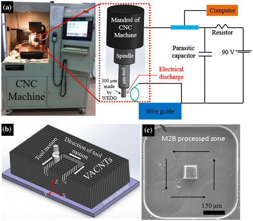
The micromechanical bending (M2B) is a mechanical process to create microstructures on vertically aligned CNT forests. This process was carried out using a servo-controlled 3-axis Micro-CNC machine (From Mikrotools Ltd as shown in Figure (a)). To carry out the M2B process, first and foremost, a cylindrical micro tool (Tungsten) of 300 μm diameter was fabricated by a manufacturing process called wire electro discharge grinding with a pre-defined voltage and capacitance (Masuzawa, Fujino, Kobayashi, Suzuki, & Kinoshita, Citation1985) (Figure (a)(right)). The fabricated micro-tool was then used to bend controllably and flatten the individual CNTs in the VACNTs array to create the micro patterns as explained in Figure (b). Figure (c) shows the Scanning Electron Microscopy (SEM) image of a typical micro pattern created on the VACNTs array/CNT forest using the M2B process. The reference position of the tool was set using the feedback from a high-resolution camera, and the motion of the tool was programmed using conventional CNC coding.
3. Experimental design
To achieve an experimental model the first step is to design the experimental runs. The numbers of factors studied in this paper are three namely tool rotational speed (S), lateral speed (V) and step size (D). A central composite design was chosen for designing the experimental runs due to its accuracy and simplicity. The objective for the designing of the experiments is to define the response variable average surface roughness (Ra) as a function of above process parameters. The range of process parameters is provided in Table . The face-centered central composite design suggested twenty experimental runs regarding the three key factors that are described in Table . According to the design algorithm (Design-Expert), the medium level of lateral speed and step size should be 5.5 mm/min and 5.5 μm respectively. However, due to the limitation of the machine resolution they were selected as 5 mm/min and 5 μm respectively. The Design-Expert software (version 8.0.4, Stat-Ease Inc., Minneapolis, USA) was used for experimental design to achieve predictive surface roughness model.
Table 1. Individual variables with their ranges and levels in central composite design
Table 2. Central composite design for three key factors (Tool rotational speed, lateral speed and step size) used in M2B method
4. Mathematical model development
All the experiments were conducted following the parameters selection as described in section 3. These experimental results were used to develop an empirical model based on response surface methodology to predict the surface roughness. Few regression models were statistically analyzed to test the lack of fit; the summary of the analysis is shown in Table .
Table 3. Lack of fit comparison between different regression model for surface roughness (Ra)
It is quite clear from Table is that quadratic is the best predicting model for surface roughness of M2B processed CNT forest sample. Quadratic model has most insignificant lack of fit. The probability value should be high (should be greater than 0.1) to accept the null hypothesis that the lack of fit is insignificant. Cubic model is not acceptable as it is aliased. The suggested quadratic model was deduced to be as follows.(1)
(1)
where, (Ra) is the average surface roughness, (S) is tool rotational speed, (V) is lateral speed, and the step size is (D).
The Analysis of Variance (ANOVA) for the model described in equation 1 was carried out using the Design-Expert software. The ANOVA analysis was carried out to check the significance of the model and significance of the each model term. The ANOVA result for the above model (Equation 1) is summarized in Table . It can be concluded from the ANOVA analysis that there are some insignificant model terms (Values of “Prob > F” less than 0.0500 indicate model terms are significant, values greater than 0.1000 indicate the model terms are not significant.). Therefore, a model reduction is required to improve the prediction accuracy by retaining significant model term. The reduced model is provided in Equation 2.(2)
(2)
Table 4. ANOVA analysis for suggested quadratic model
The ANOVA analysis of Equation (2) is provided in Table . In the new model all the terms are significant.
Table 5. ANOVA analysis of reduced quadratic model
5. Results and discussion
Experiments were conducted according to the plan described in Table . Average surface roughness was measured using noncontact Atomic Force Microscopy (AFM) and data were fed to generate the best fit model into the algorithm. Measurements were carried out using Park XE-100 model AFM machine for three times for same sample and average value was used.
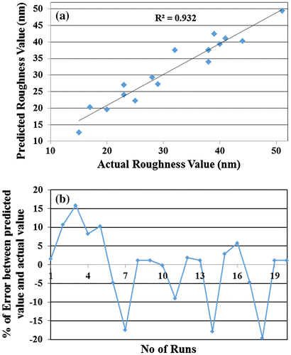
The predicted surface roughness shows in good agreement with the experimental surface roughness as described in Figure . Figure (a) shows the relationship between the predicted value of the surface roughness and actual value of the surface roughness. The trend line for this is a linear graph going with negligible intercept, and all the actual data are scattered around it with reasonable tolerance. Figure (b) describes the error percentage between the predicted and actual surface roughness. The limit is within 20%, which is considered to be reasonable for such low surface roughness value.
Figure 2. Analysis of predicted and experimental results: (a) Predicted VS Actual surface roughness and (b) Percentage of error between predicted and experimental surface roughness for the 20 experimental runs described in Table .
5.1. Influence of M2B process parameters on the average surface roughness
Figure shows the relationship between pairs of process parameters on the surface roughness of the patterned CNT forest surface. The ANOVA (Analysis of variance) analysis suggested that the proposed model is significant. F value of the individual parameter indicated the influence of the parameter on the response i.e. the surface roughness. According to the analysis, Lateral speed and step size have higher influence than the tool rotational speed. This is why we can see from Figure (a) and (b) that variation of tool rotational speed does not change surface roughness significantly. On the other hand, it is quite evident from the Figure (c) that lateral speed and step size are two very important factors that affect the response considerably. The morphological study also substantiates the above explanation. Figure shows the FESEM (Field Emission Scanning Electron Microscope) images of three M2B processed CNT forest structures with different parameters. In all the cases lateral speed and step size were kept constant at 1 mm/min and 1 μm respectively, however, the rotational speed was varied at 1,000, 1,500, and 2,000 RPM. It is clear from Figure that surface morphology is almost the same for all three cases, although, the tool rotational speed was varied in three different levels. However, if the tool rotational speed is very low it cannot bring flexible and fragile nanotubes together that eventually causes cracks and bad surface roughness on the processed CNT zone (Mohd Razib, Saleh, & Hassan, Citation2014).
Figure 3. Effect of parameters on surface roughness used in micromechanical bending (M2B) of VACNTs: (a) At constant step size of 5 μm, (b) At constant lateral speed 5 mm/min and (c) At constant tool rotational speed 1,500 RPM.
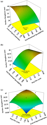
Figure 4. FESEM images show the effect of Rotational Speed on the M2B process of VACNTs: (a), (b) and (c) were carried out at 1 mm/min Lateral Speed and 1 μm Step Size. Tool rotation speed was 1,000 RPM, 1,500 RPM and 2,000 RPM respectively.
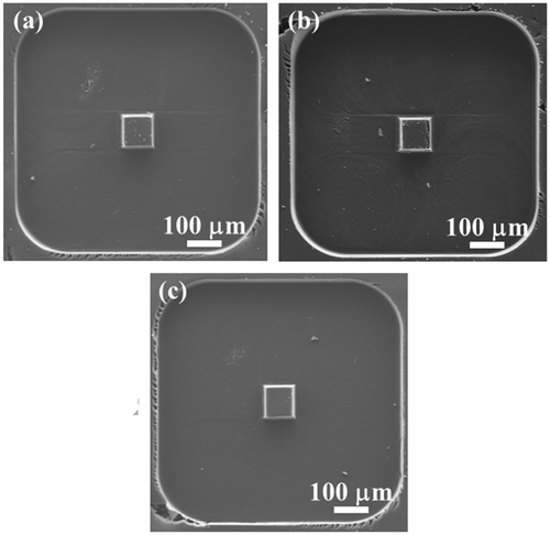
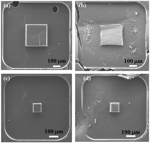
Figure explains the effect of lateral speed and step size on the morphology of the resultant M2B processed structures. Structures of Figure (a) and (b) were fabricated with same tool rotational speed (1,000 RPM) and step size (1 μm). However, lateral speed for the two cases was 1 and 10 mm/min respectively. The CNT forest is very delicate and sensitive to the touch; even a very small force could transform the structure of CNT forests. Therefore, higher lateral speed caused a detrimental effect on the surface texture of the M2B processed CNT zone as compared in Figure (a) and (b). Similar to faster lateral speed, larger step size in a single go could exert excessive force on processing zone of the CNT forest which may result in poor surface quality. Comparison between Figure (c) and (d) could further validate the statement. It is obvious from Figure that Figure (c) has smoother surface than Figure (d). The only difference between these two figures is that the step size is considerably higher for Figure (d) (10 μm) as compared to Figure (c) (1 μm). The tool rotational speed and lateral speed for both the cases were 1,000 RPM and 1 mm/min respectively.
Figure 5. SEM images M2B processed of VACNTs: (a), (b) were carried out at 1,000 RPM tool rotational speed and 1 μm Step Size, Lateral Speed was 1 and 10 mm/min respectively and (c), (d) were carried out at 1,000 RPM tool rotational speed and 1 mm/min Lateral Speed, Step size was 1 and 10 μm respectively.
5.2. Model validation
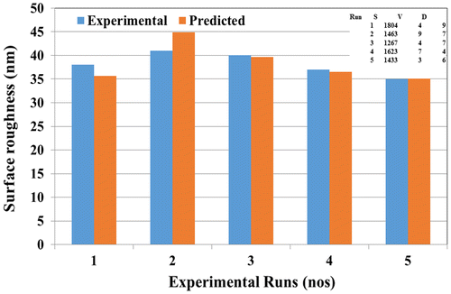
After developing the empirical model experimental validation was carried out to confirm the mathematical accuracy of the suggested model for the Micromechanical Bending Process (M2B) of the CNT forest. In order to carry out the validation five different levels of parameters were selected within their range. The predicted surface roughness by the model described by equation 2 was verified with the experimental data. Figure shows the comparison between the experimental surface roughness and predicted surface roughness. The average discrimination was found to be in a range of 10% which can be considered to be very accurate.
6. Application example of M2B processing of CNT forest
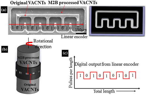
The micromechanical bending method has potential impact in MEMS and sensor fabrication as discussed by Mohd Razib et al. (Citation2014) because of its flexibility. In this paper, we have demonstrated the use of M2B patterned CNT forest as an encoder. It was discussed earlier (Asyraf et al., Citation2016) that M2B process makes the CNT forest reflective at the patterned zone. The reflectance will be sharper if the surface roughness of the processed CNT forest is smooth with low roughness value. Therefore, the most optimal parameters were used to produce the encoders which are 2,000 rpm (tool rotational speed), 1 mm/min (lateral speed) and 1 μm (step size). The resultant surface roughness was found to be 15 nm. The SEM image of the fabricated encoder is shown in Figure (a). The original CNT forest surface acts as a black absorber and the processed CNT surface acts as a reflector. An optical emitter/receiver package was used to detect the pulses from the CNT encoder attached to a moving body as described in Figure (c). CNT forest is well-known among the researchers for its flexibility. It is also a fact that the CNT forest can be grown on a flexible substrate like metal (Patole et al., Citation2011). Therefore, a sample of CNT forest grown on the flexible substrate can be patterned to make encoder that can be used both for angular and linear measurement as explained in Figure (a) and (b).
7. Conclusion
Micromechanical bending (M2B) is a mechanical post processing technique for vertically aligned carbon nanotubes (VACNT). M2B processing has various useful engineering applications. In this paper, an attempt has been made to develop an empirical model using response surface methodology to understand better the M2B operation of VACNT array. It was observed that higher tool rotation with low lateral speed and step size is favorable for the M2B process to produce smoother surface. However, effects of lateral speed and step size were more prominent than tool rotational speed on the surface quality of the processed zone of the VACNT array. The mathematical model was validated experimentally with very good accuracy (~10%). Finally, a CNT forest based encoder was fabricated (using M2B process) by the best parameter and tested by shining laser from a laser emitter/receiver to identify its potentiality to be used for measuring linear and/or angular displacement. Further, it has been proposed that if VACNT is grown onto the flexible substrate, then M2B process can produce encoder that would be flexible enough to be used both for linear and angular displacement measurement.
| Nomenclature | ||
| Ra | = | Average surface roughness |
| S | = | Tool rotational speed |
| V | = | Lateral speed |
| D | = | Step size |
Funding
This work was supported by research grants provided by Ministry of Higher Education, Malaysia [grant number FRGS13-083-0324]; Ministry of Science Technology and Innovation [grant number SF14-008-0058].
Acknowledgment
Authors acknowledge Dr. Alireza Nojeh from the University of British Columbia for providing us with the CNT forests samples.
Additional information
Notes on contributors
T. Saleh
Dr T. Saleh has been working as an associate professor in the Department of Mechatronics Engineering of International Islamic University Malaysia. His research interest includes Nonconventional Micro-fabrication Technology, CNT based sensor development and Customized Machine Development.
References
- Ando, Y., & Zhao, X. (2006). Synthesis of Carbon nanotubes by arc-discharge method. New Diamond and Frontier Carbon Technology, 16, 123–137.
- Angulakshmi, V. S., Sivakumar, N., & Karthikeyan, S. (2012). Response Surface Methodogy for optimizing Process Parameters for Synthesis of Carbon Nanotubes. Journal of Environmental Nanotechnology, 1, 40–45.
- Arbizu, I. P., & Perez, C. L. (2003). Surface roughness prediction by factorial design of experiments in turning processes. Journal of Materials Processing Technology, 143–144, 390–396.10.1016/S0924-0136(03)00407-2
- Choudhury, I., & El-Baradie, M. (1997). Surface roughness prediction in the turning of high-strength steel by factorial design of experiments. Journal of Materials Processing Technology, 67, 55–61.10.1016/S0924-0136(96)02818-X
- George, P. M., Raghunath, B. K., Manocha, L. M., & Warrier, A. M. (2004). EDM machining of carbon–carbon composite—a Taguchi approach. Journal of Materials Processing Technology, 145, 66–71.10.1016/S0924-0136(03)00863-X
- Habib, S. S. (2009). Study of the parameters in electrical discharge machining through response surface methodology approach. Applied Mathematical Modelling, 33, 4397–4407.10.1016/j.apm.2009.03.021
- Hutchison, D. N., Morrill, N. B., Aten, Q., Turner, B. W., Jensen, B. D., Howell, L. L., … Davis, R. C. (2010). Carbon nanotubes as a framework for high-aspect-ratio MEMS fabrication. Journal of Microelectromechanical Systems, 19, 75–82.10.1109/JMEMS.2009.2035639
- Khalid, W., Ali, M. S. M., Dahmardeh, M., Choi, Y., Yaghoobi, P., Nojeh, A., & Takahata, K. (2010). High-aspect-ratio, free-form patterning of carbon nanotube forests using micro-electro-discharge machining. Diamond and Related Materials, 19, 1405–1410.10.1016/j.diamond.2010.08.007
- Liu, Y., He, J-H., & Yu, J-Y. (2008). Bubble-electrospinning: A novel method for making nanofibers. Journal of Physics: Conference Series, 96, 012001.
- Mansour, A., & Abdalla, H. (2002). Surface roughness model for end milling: A semi-free cutting carbon casehardening steel (EN32) in dry condition. Journal of Materials Processing Technology, 124, 183–191.10.1016/S0924-0136(02)00135-8
- Marandi, R., Khosravi, M., Olya, M. E., Vahid, B., & Hatami, M. (2011). Photocatalytic degradation of an azo dye using immobilised TiO 2 nanoparticles on polyester support: Central composite design approach. Micro & Nano Letters, 6, 958–963.10.1049/mnl.2011.0348
- Masuzawa, T., Fujino, M., Kobayashi, K., Suzuki, T., & Kinoshita, N. (1985). Wire electro-discharge grinding for micro-machining. CIRP Annals-Manufacturing Technology, 34, 431–434.10.1016/S0007-8506(07)61805-8
- Mohd Asyraf, M. R., Masud Rana, M., Saleh, T., Fan, H. D. E., Koch, A. T., Nojeh, A., … Suriani, A. B. (2016). Study on micro-patterning process of vertically aligned carbon nanotubes (VACNTs). Fullerenes, Nanotubes and Carbon Nanostructures, 24, 88–99.10.1080/1536383X.2015.1119126
- Mohd Razib, M., Saleh, T., & Hassan, M. (2014). Micro-mechanical bending (M 2 B) method for carbon nanotube (CNT) based sensor fabrication. IEEE International Conference on Smart Instrumentation, Measurement and Applications (ICSIMA) (pp. 1–5), Kuala Lumpur.
- Öktem, H., Erzurumlu, T., & Kurtaran, H. (2005). Application of response surface methodology in the optimization of cutting condi-tions for surface roughness. Journal of Materials Processing Technology, 170, 11–16.
- Patole, S. P., Kim, H-I., Jung, J-H., Patole, A. S., Kim, H-J., Han, I-T., ... Ji-Beom, Y. (2011). The synthesis of vertically-aligned carbon nanotubes on an aluminum foil laminated on stainless steel. Carbon, 49, 3522–3528.10.1016/j.carbon.2011.04.051
- Saleh, T., Dahmardeh, M., Bsoul, A., Nojeh, A., & Takahata, K. (2011). Field-emission-assisted approach to dry micro-electro-discharge machining of carbon-nanotube forests. Journal of Applied Physics, 110, 103305.10.1063/1.3663438
- Sahin, Y., & Motorcu, A. R. (2005). Surface roughness model for machining mild steel with coated carbide tool. Materials & Design, 26, 321–326.10.1016/j.matdes.2004.06.015
- Sal, W. B., Salah, N. B., & Lebrun, J. (2001). Influence of machining by finishing milling on surface characteristics. International, Journal of Machine Tools and Manufacture, 41, 443–450.
- Sivasankari, S., & Babu, J. (2013). Application of response surface methodology based central composite design for validation and optimization of solar photovoltaic characteristics through MATLAB. In International Conference on Green Computing, Communication and Conservation of Energy (ICGCE), IEEE.
- Yang, Z-P., Ci, L., Bur, J. A., Lin, S-Y., & Ajayan, P. M. (2008). Experimental observation of an extremely dark material made by a low-density nanotube array. Nano Letters, 8, 446–451.10.1021/nl072369t
- Zhang, B., Kang, F., Tarascon, J-M., & Kim, J-K. (2016). Recent advances in electrospun carbon nanofibers and their application in electrochemical energy storage. Progress in Materials Science, 76, 319–380.10.1016/j.pmatsci.2015.08.002

