 ?Mathematical formulae have been encoded as MathML and are displayed in this HTML version using MathJax in order to improve their display. Uncheck the box to turn MathJax off. This feature requires Javascript. Click on a formula to zoom.
Abstract
Background: We investigated the methods of calibrating an endoscope to an optical tracking system (OTS) for high accuracy augmented reality (AR)-based surgical navigation. We compared the possible calibration methods, and suggested the best method in terms of accuracy and speed in a medical environment. Material and methods: A calibration board with an attached OTS marker was used to acquire the pose data of the endoscope for the calibration. The transformation matrix from the endoscope to the OTS marker was calculated using the data. The calibration was performed by moving either the board or the endoscope in various placements. The re-projection error was utilized for evaluating the matrix. Results: From the statistical analysis, the method of moving the board was significantly more accurate than the method of moving the endoscope (p < 0.05). This difference resulted mainly from the uneven error distribution in the OTS measurement range and also the hand tremor in holding the endoscope. Conclusions: To increase the accuracy of AR, camera-to-OTS calibration should be performed by moving the board, and the board and the endoscope should be as close as possible to the OTS. This finding can contribute to improving the visualization accuracy in AR-based surgical navigation.
Public Interest Statement
In implementing an augmented reality (AR)-based surgical navigation system, an issue is to overlay reconstructed virtual 3-D models on real ones with high accuracy. In particular, for surgical fields where an endoscope is used, an alignment of coordinate systems between the endoscope and an optical tracking system (OTS), called camera-to-OTS calibration in this article, is a necessary procedure, and its result highly affects the AR accuracy. The calibration is generally performed by moving the endoscope. This requires a large measurement range of the OTS and thus it makes the result of the calibration inaccurate possibly because the OTS has a spatial error which increases with the distance between tracked objects and the OTS. This article proposes a method to move the calibration board instead of the endoscope for the calibration and shows that moving the board can significantly improve the performance of the calibration.
1. Introduction
Augmented reality (AR) is an emerging technology where virtual objects are superimposed onto camera images. Recently, AR has been used in surgical procedures that use medical cameras such as an endoscope or microscope. AR-based surgical navigation provides information on the shape or location of tumors, blood vessels or nerves which are difficult for surgeons to recognize by direct vision. AR information for specific organs or areas of interest is directly overlaid on endoscopic or microscopic images without using an extra monitor to display it, which avoids distracting the surgeon’s vision (King et al., Citation2000; Sielhorst, Feuerstein, & Navab, Citation2008; Winne, Khan, Stopp, Jank, & Keeve, Citation2011).
There are two key elements that affect the accuracy of AR-based surgical navigation. One is the registration to determine the relationship, in Equation (1), between the patient and image frames (Arun, Huang, & Blostein, Citation1987; Besl & McKay, Citation1992; Horn, Citation1987; Nottmeier & Crosby, Citation2007; Schicho et al., Citation2007; West, Fitzpatrick, Toms, Maurer, & Maciunas, Citation2001). The second is the camera calibration with respect to the optical tracking system (OTS), which is the process to determine the relationship,
in Equation (1), between the cameras and the OTS marker attached to the camera. We refer to this calibration hereafter as ‘camera-to-OTS calibration’.
Due to this second element, ensuring an acceptable accuracy in AR-based surgical navigation is more difficult than in the virtual reality-based surgical navigation achieved by using only the first element. Nevertheless, camera-to-OTS calibration has been little studied so far compared to patient-image registration.
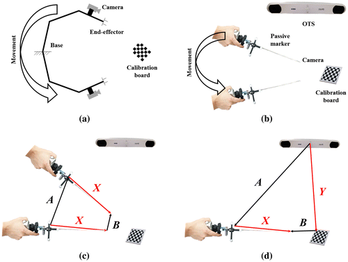
Camera-to-OTS calibration methods are fundamentally similar to hand–eye calibration methods used to determine the relationship between the end-effector of a robot and the camera attached to the end-effector in typical robotic applications (Andreff, Horaud, & Espiau, Citation2001; Chen, Citation1991; Chou & Kamel, Citation1991; Daniilidis, Citation1999; Dornaika & Horaud, Citation1998; Li, Wang, & Wu, Citation2010; Shiu & Ahmad, Citation1989; Tsai & Lenz, Citation1989; Zhuang, Roth, & Sudhakar, Citation1994). Despite their similarity, camera-to-OTS calibration using the OTS for AR-based surgical navigation systems differs from that using the robotic system in two key ways. First, the camera must be moved manually without the assistance of the robot mechanism, as shown in Figure (a) and (b). Therefore, the weight and the size of the medical cameras make the calibration procedure inconvenient and may cause significant error due to hand tremor of the user while moving the camera. The second difference, the main focus in this paper, arises from the use of the OTS instead of the robot encoders to measure the pose of the camera. The OTS has a unique spatial error distribution which increases with the distance from the target. Several researchers have discussed the distribution of spatial error of the OTS (Gerard & Collins, Citation2015; Khadem et al., Citation2000; Koivukangas, Katisko, & Koivukangas, Citation2013; Schmidt, Berg, Ploeg, & Ploeg, Citation2009; Wiles, Thompson, & Frantz, Citation2004), and reported measurement strategies to reduce the effect of the error: to track the target as close as possible to the OTS (Gerard & Collins, Citation2015; Khadem et al., Citation2000; Wiles et al., Citation2004), and to have a small measurement volume (Schmidt et al., Citation2009). This spatial error also makes typical hand–eye calibration methods inaccurate and this is why we should consider a different approach.
Figure 1. Camera-to-OTS calibration procedure: (a) Hand–eye calibration in robotics, and (b) equivalent camera-to-OTS calibration in clinical environments. A robot hand connected to an endoscope corresponds to an OTS marker connected to an endoscope. The encoders of the robot joints correspond to an OTS in AR. (c) AX = XB and (d) AX = YB to find X by the camera-to-OTS calibration.
In this study, we investigated the reason why the typical hand–eye calibration methods produce larger errors in clinical applications than in robotic applications. In addition, based on the comparison of possible camera-to-OTS calibration methods under three endoscope and OTS settings, the best approach was suggested for the AR display with an endoscope. Our results can also be utilized in solving other camera and external sensor calibration problems.
2. Material and methods
2.1. AR navigation and camera-to-OTS calibration
The basic concept of AR navigation is represented in Figure . {I}, {P}, {O}, {CM}, and {C} represent the frames of the image, patient, OTS, endoscope-affixed OTS marker, and endoscope. As shown in Figure , we can build the following equation straightforwardly:(1)
(1)
Figure 2. Basic concept of the AR navigation system. A virtual object in image frame {I} is transformed into endoscope frame {C} by the process in Equation (1).
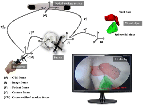
where and
are 3D points in the image and endoscope frames,
and
are 4 × 4 homogeneous transformation matrices (HTM) representing the poses (position and orientation) of the patient and endoscope, which are directly obtained from the OTS,
and
are HTMs obtained from the patient-image registration and camera-to-OTS calibration.
An arbitrary point in image frame is transformed to the endoscope frame by using Equation (1). The accuracy of
and
is determined by the performance of the OTS, which is not of interest in this study; therefore,
and
are the main factors which determine the final accuracy of the AR overlay. The registration matrix
is not the subject of this study. Finally, finding
which is the result of camera-to-OTS calibration, remains as the goal.
A typical method of performing camera-to-OTS calibration is the process to solve AX = XB, which is defined in Figure (c), where A is an HTM defined by the pose data from OTS, B is an HTM defined by the traditional camera calibration, and X is the target HTM to find, which is equal to in Equation (1). There is also a modified method of AX = XB, which is referred to as AX = YB, which is defined in Figure (d). The process to solve AX = YB is similar to that for AX = XB; however, in addition to X, the solution to AX = YB provides Y, which is the transformation from the OTS to the board, which can be used to find X differently by direct cascade multiplication without using the least-square sense. At least three pose data of A and B with different orientations and positions are required to solve AX = XB or AX = YB. For this, an endoscope attached to an OTS marker must be re-located multiple times while the OTS and the board are fixed. After acquiring sufficient pose data, X is calculated using A and B with the least-square sense.
2.2. AX = BYC configuration with a calibration board
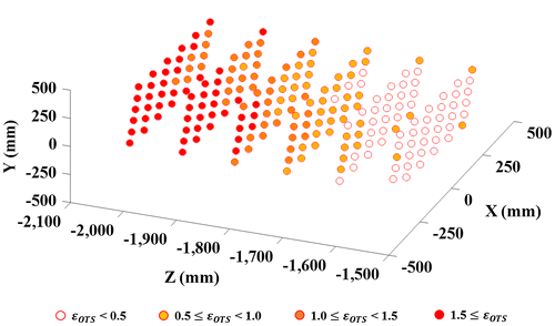
Unlike the robotic encoder, the spatial error of the OTS increases with the distance to the target tracked, as shown in Figure . As the endoscope is moved to locations far from the OTS to acquire the necessary pose data for the calibration, the spatial error of the OTS strongly affects the accuracy. To reduce the influence of the spatial error, we proposed a method whereby the user moves the calibration board instead of the endoscope. The advantage of this method is explained below.
Figure 3. Distribution of spatial error of the OTS. The spatial error, ɛOTS (mm), clearly increases when the measured object is far from the OTS according to the z-axis.
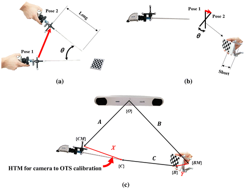
To move the calibration board instead of the endoscope, the OTS marker was attached to the calibration board before acquiring the pose data. The movement ranges of the endoscope and the calibration board are shown in Figure (a) and (b). Red arrows represent the movements from pose 1 to pose 2. At the same rotation angle θ, the displacement of the board is much smaller than that of the endoscope, because the displacement depends on the distance between the OTS marker and the endoscope, or the OTS marker and the calibration board. The OTS marker is attached to the endoscope head, which is far from the distal, whereas the calibration board has the marker close to the rotational axis.
Figure 4. Comparison of the movement range of: (a) moving the endoscope and (b) moving the calibration board. The red arrows represent the movement ranges when the endoscope and the board are rotated with θ. Moving the calibration board shows a smaller movement range than moving the endoscope. (c) AX = BYC configuration. By attaching an OTS marker to the calibration board, it can be moved instead of the endoscope to acquire the pose data.
Schmidt et al. (Citation2009) reported that a small measurement range is recommended to reduce the error. Moving the board instead of the endoscope is expected to be less affected by the spatial error of the OTS, thanks to the relatively small movement range. Additionally, because the board is lighter and smaller than the endoscope, the calibration procedure will be more convenient and faster.
By attaching an OTS marker to the board, AX = BYC, which is a modified version of AX = YB, is formulated as shown in Figure (c). {BM} and {B} represent the frames of the board-affixed marker and the board itself. In AX = BYC, A represents the HTM from the OTS to the endoscope-affixed marker, B represents the HTM from the OTS to the board-affixed marker, C represents the HTM from the origin of the board to the tip of the endoscope, Y represents the HTM from the board-affixed marker to its origin, and X is the target calibration matrix. We will use a symbolic equation AX = BYC to represent the method of moving the board instead of moving the endoscope.
2.3. Solving AX = BYC
Three steps are required to solve AX = BYC. The first step is to acquire n-pose data by moving the board with a sufficient angle between the poses. According to the report by Tsai and Lenz (Tsai & Lenz, Citation1989), the accuracy of the camera-to-OTS calibration depends on this angle between the poses. The second step is to multiply both sides of AX = BYC with the inverse of B, thus yielding DX = YC, where , which is the same form as AX = YB. The last step is to calculate the DX = YC equation using the previous methods to solve the AX = YB equation. In this step, the Kronecker product-based computation method was used (Li et al., Citation2010). This method begins by separating the rotation and the translation as follows:
(2)
(2)
(3)
(3)
where R is a 3 × 3 rotation matrix and is a 3 × 1 translation vector, and their subscripts represent symbols of HTMs before separation, i.e.,
is the rotation matrix of D. Based on the definition of the Kronecker product and vectorization, Equations (2) and (3) can be expressed as Equations (4) and (5), respectively.
(4)
(4)
(5)
(5)
where ⊗ is a Kronecker product operator defined in Equation (6), vec(∙) is a vectorization operator that reshapes an n × m matrix to an nm × 1 vector, and I is an identity matrix.(6)
(6)
Finally, Equations (4) and (5) yield the following equation where i represents an index of the acquired pose data, generally known as the least-square problem:
(7)
(7)
The dimensions of ,
, and
, are 12 × 24, 24 × 1, and 12 × 1, respectively. With multiple pose data, Equation (7) can be simplified to Equation (9):
(9)
(9)
where M and N represent and
, respectively, and n is the number of poses. Equation (9) is solved using the pseudo inverse of M for n > 2. Note that the vector v in Equation (9) has both X and Y information.
2.4. Experimental setup
In the experiments, camera-to-OTS calibration was performed by using the following instruments: a calibration board with a 5 × 4 pattern array of corner points in which the distance between the corner points was 15 mm; an endoscopic system with 0 degree scope cylinder (1188HD, Stryker, Kalamazoo, MI, USA) to capture the pattern on the board; an OTS (Polaris Spectra, Northern Digital Inc., Waterloo, Canada) to track the poses of the markers attached to the endoscopes and the board.
Camera calibration was performed by using Zhang’s method before camera-to-OTS calibration (Zhang, Citation2000). Thirty pattern images were used for the camera calibration. The image resolution was 720 × 576 pixels with 30 frames per second (fps).
Different layouts were considered and applied as shown in Figure because the influence of the spatial error of the OTS changed with the positions of the endoscope, the OTS, and the board. Three layouts, named layout 1, 2, and 3 in this study, were chosen after considering the actual positioning of the OTS and the endoscope in clinical environments. Figure (a), (b) and (c) show layout 1, 2, and 3, respectively. Layout 1 simulates the case in which both the endoscope and the board are relatively close to the OTS. Because the OTS has spatial error that increases with the distance, layout 1 should have the least spatial error due to the short distance. Layouts 2 and 3 simulate the cases in which either the endoscope or the board is relatively far from the OTS. In addition, by considering the line-of-sight problem of the OTS in each layout, the location and direction of the markers on the endoscope and the board were carefully selected.
Figure 5. The three layouts used for the positioning of the endoscope, tracker, and calibration board: (a) In layout 1, both the endoscope and the calibration board are relatively close to the OTS; in (b) and (c), one of them is relatively far from the OTS.
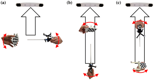
In each layout, camera-to-OTS calibration was performed 30 times. For each trial, the board was moved to 30 locations with different positions and orientations. The same process was repeated by moving the endoscope instead of the board.
The re-projection error was calculated to measure the accuracy of the camera-to-OTS calibration. After the camera calibration, A, B, X, and Y were used to compute the re-projection instead of extrinsic parameter, C as shown in Equation (10):(10)
(10)
where is a 2D point in the image coordinates,
and
are the focal lengths,
and
are the principal points; P is a 3D corner point of the board; A and B are pose data obtained from the OTS; and X is the result of the camera-to-OTS calibration. Y represents the transformation from the board and the marker attached to the board. As defined in Equation (10), the point of the board (P) in 3D is projected onto the image plane (
) in 2D.
On the board used there were 20 corner points. The total re-projection error of the camera-to-OTS calibration, ε, is defined in Equation (11):(11)
(11)
where m is the number of images, n is the number of corner points of the board, and p is the corner points obtained by image processing of the m-th picture. The re-projection points computed by the results of the camera-to-OTS calibration were given as . For the evaluation, 50 poses that had not been used previously for the camera-to-OTS calibration were selected. Note that we performed camera-to-OTS calibration 30 times with 30 poses for each trial, and the results were evaluated by using 50 different poses that were not used for the calibration process.
3. Results
The re-projection errors for camera calibration were measured to 0.26 pixels, which is comparable to previously reported works (Lapeer, Chen, Gonzalez, Linney, & Alusi, Citation2008; Shahidi et al., Citation2002).
The solution from moving the board, referred to as AX = BYC, was compared with two solutions from moving the endoscope, referred to as AX = XB (Figure (c)) and AX = YB (Figure (d)). A t-test with a one-sided significance level of 5% was also performed to evaluate the statistical significance using OriginLab software (OriginPro 2015, Northampton, MA, USA). Note that moving the endoscope has two kinds of solutions while moving the board has only one solution, which produces three results altogether, as shown in Figure (a).
Figure 6. Comparison for measured errors and time-taken: (a) Camera-to-OTS calibration errors on 30 trials in each layout. (b) Time-taken to acquire 30 poses data. “ME” and “MB” represent moving the endoscope and moving the calibration board, respectively.
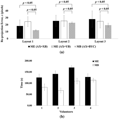
Figure (a) shows the re-projection errors for each layout over 30 trials. The AX = BYC method was more accurate than the conventional methods in all layouts (p < 0.05). For the conventional methods, several peak values were observed in the error. However, the AX = BYC method showed consistency and did not exhibit peak values in the error (see standard deviation).
Furthermore, the time required to perform camera-to-OTS calibration was measured for four volunteers who have less experience of the camera-to-OTS calibration procedure. Most time-consuming task in the camera-to-OTS calibration procedure is to collect necessary pose data; therefore, we measured the time required to collect necessary pose data. Each volunteer acquired 30 poses, and repeated the acquisition task five times. As a result, an obvious difference was observed as shown in Figure (b). When using the AX = BYC method, the mean task time for all volunteers was approximately 93 s, while it was 141 s by the conventional method. This signifies that the AX = BYC method can reduce the calibration time.
4. Discussion
In this study, camera-to-OTS calibration methods for AR navigation with an OTS were investigated in terms of the accuracy, speed, and convenience. Due to the inherent spatial error of the OTS, conventional hand–eye calibration methods, AX = XB and AX = YB, which need to move the camera to acquire pose data did not perform well in clinical environments. In contrast, the method of moving the calibration board instead of the camera showed better performance thanks to the smaller movement range. This is easily achieved by attaching an additional OTS marker to the board and establishing AX = BYC, a modified form of AX = YB.
The AX = BYC method was most effective in the case of layout 1, which is the most sensitive to the spatial error of the OTS because the endoscope and the board mainly move along the z-axis of the OTS. On the other hand, in layouts 2 and 3, the influence of the spatial error is less than that in layout 1 because the board mainly moves in the x and y directions, while the spatial error mainly increases along the z-axis of the OTS. Additionally, in the case of layout 3, due to the position of the endoscope, the line of sight of the OTS was frequently disconnected. Therefore, the movement of the endoscope was significantly restricted. This restriction may have caused insufficient angles between the pose data, thus increasing the calibration error.
In comparison with AX = XB, the AX = BYC form has an additional source of error due to the OTS marker being attached to the board. In addition, the AX = BYC form has one more unknown parameter, Y, which is not an essential element for AR navigation. Nevertheless, the AX = BYC form showed a more accurate result than AX = XB. This indicates that the advantage in handling the spatial error of the OTS compensates for the loss due to the additional marker attached to the board. To take advantage of this more effectively, the marker must be attached to a location that is sufficiently close to the frame of the board.
Chen et al. (Citation2012) used the most similar method to the AX = BYC method in terms of using the board with the OTS marker. However, they solved X using an orthogonal Procrustes analysis method. This method requires a manual task to take several points on the board for solving Y. This is inconvenient for users and the accuracy varies from individual to individual.
Although all of the experiments were performed with an endoscope, the same method is applicable to surgical microscopes and other camera systems for AR as well.
5. Conclusions
In this study, we tried to find the most effective method for the camera-to-OTS calibration to improve AR navigation with the OTS. Through the experiments using re-projection, it was found that moving the board showed significantly higher accuracy than moving the endoscope (p < 0.05), particularly when both the endoscope and the board are relatively close to the OTS. The AX = BYC method also improved the speed of the calibration process. This finding can contribute to improving the visualization accuracy in various AR applications.
Funding
This work was supported by the Industrial Source Technology Development Program [grant number 10040097] and the Technology Innovation Program [grant number 10063309] funded by the Ministry of Trade, Industry & Energy of Korea, and the Health and Medical R&D Program [grant number HI13C1634] funded by the Ministry of Health and Welfare of Korea.
Additional information
Notes on contributors
Jaesung Hong
Jaesung Hong received the PhD degree in 2004 at The University of Tokyo in Japan. He is currently a professor of Department of Robotics Engineering at DGIST in South Korea. His research interests include augmented reality for medicine, surgical navigation, and surgical robotics. At the University of Tokyo, he has developed the first ultrasound-guided needle insertion robot tracking a movable and deformable organ. While he worked at Kyushu University Hospital in Japan, he developed customized surgical navigation systems and clinically applied them in various surgeries. Since 2016, he has joined the IEEE/RAS technical committee on surgical robotics as a co-chair, and worked as an associate editor for IEEE RA-L.
References
- Andreff, N., Horaud, R., & Espiau, B. (2001). Robot hand-eye calibration using structure-from-motion. The International Journal of Robotics Research, 20, 228–248.10.1177/02783640122067372
- Arun, K. S., Huang, T. S., & Blostein, S. D. (1987). Least-squares fitting of two 3-D point sets. IEEE Transactions on Pattern Analysis and Machine Intelligence, 5, 698–700.10.1109/TPAMI.1987.4767965
- Besl, P. J., & McKay, N. D. (1992). A method for registration of 3-D shapes. In IEEE Transactions on Pattern Analysis and Machine Intelligence, 144, 239–256.
- Chen, E. C., Sarkar, K., Baxter, J. S., Moore, J., Wedlake, C., & Peters, T. M. (2012). An augmented reality platform for planning of minimally invasive cardiac surgeries. In International Society for Optics and Photonics on SPIE Medical Imaging, 831617. doi:10.1117/12.911998
- Chen, H. H. (1991). A screw motion approach to uniqueness analysis of head-eye geometry. In IEEE Computer Society Conference on Computer Vision and Pattern Recognition, Proceedings CVPR’91 (pp. 145–151), IEEE.10.1109/CVPR.1991.139677
- Chou, J. C., & Kamel, M. (1991). Finding the position and orientation of a sensor on a robot manipulator using quaternions. The International Journal of Robotics Research, 10, 240–254.10.1177/027836499101000305
- Daniilidis, K. (1999). Hand-eye calibration using dual quaternions. The International Journal of Robotics Research, 18, 286–298.10.1177/02783649922066213
- Dornaika, F., & Horaud, R. (1998). Simultaneous robot-world and hand-eye calibration. IEEE Transactions on Robotics and Automation, 14, 617–622.10.1109/70.704233
- Gerard, I. J., & Collins, D. L. (2015). An analysis of tracking error in image-guided neurosurgery. International Journal of Computer Assisted Radiology and Surgery, 10, 1579–1588.10.1007/s11548-014-1145-2
- Horn, B. K. (1987). Closed-form solution of absolute orientation using unit quaternions. Journal of the Optical Society of America A, 4, 629–642.10.1364/JOSAA.4.000629
- Khadem, R., Yeh, C. C., Sadeghi-Tehrani, M., Bax, M. R., Johnson, J. A., Welch, J. N., … Shahidi, R. (2000). Comparative tracking error analysis of five different optical tracking systems. Computer Aided Surgery, 5, 98–107.10.3109/10929080009148876
- King, A. P., Edwards, P. J., Maurer, Jr., C. R., Cunha, D. A., Gaston, R. P., Clarkson, M., … Strong, A. J. (2000). Stereo augmented reality in the surgical microscope. Presence: Teleoperators and Virtual Environments, 9, 360–368.10.1162/105474600566862
- Koivukangas, T., Katisko, J., & Koivukangas, J. P. (2013). Technical accuracy of optical and the electromagnetic tracking systems. SpringerPlus, 2(1), 1–7.
- Lapeer, R., Chen, M., Gonzalez, G., Linney, A., & Alusi, G. (2008). Image-enhanced surgical navigation for endoscopic sinus surgery: Evaluating calibration, registration and tracking. The International Journal of Medical Robotics and Computer Assisted Surgery, 4, 32–45.10.1002/(ISSN)1478-596X
- Li, A., Wang, L., & Wu, D. (2010). Simultaneous robot-world and hand-eye calibration using dual-quaternions and Kronecker product. International Journal of Physical Sciences, 5, 1530–1536.
- Nottmeier, E. W., & Crosby, T. L. (2007). Timing of paired points and surface matching registration in three-dimensional (3D) image-guided spinal surgery. Journal of Spinal Disorders & Techniques, 20, 268–270.10.1097/01.bsd.0000211282.06519.ab
- Schicho, K., Figl, M., Seemann, R., Donat, M., Pretterklieber, M. L., Birkfellner, W., … Bergmann, H. (2007). Comparison of laser surface scanning and fiducial marker–based registration in frameless stereotaxy. Journal of Neurosurgery, 106, 704–709.10.3171/jns.2007.106.4.704
- Schmidt, J., Berg, D. R., Ploeg, H.-L., & Ploeg, L. (2009). Precision, repeatability and accuracy of Optotrak® optical motion tracking systems. International Journal of Experimental and Computational Biomechanics, 1, 114–127.10.1504/IJECB.2009.022862
- Shahidi, R., Bax, M. R., Maurer, C. R., Johnson, J. A., Wilkinson, E. P., Wang, B., … Khadem, R. (2002). Implementation, calibration and accuracy testing of an image-enhanced endoscopy system. IEEE Transactions on Medical Imaging, 21, 1524–1535.10.1109/TMI.2002.806597
- Shiu, Y. C., & Ahmad, S. (1989). Calibration of wrist-mounted robotic sensors by solving homogeneous transform equations of the form AX=XB. IEEE Transactions on Robotics and Automation, 5, 16–29.10.1109/70.88014
- Sielhorst, T., Feuerstein, M., & Navab, N. (2008). Advanced medical displays: A literature review of augmented reality. Journal of Display Technology, 4, 451–467.10.1109/JDT.2008.2001575
- Tsai, R. Y., & Lenz, R. K. (1989). A new technique for fully autonomous and efficient 3D robotics hand/eye calibration. IEEE Transactions on Robotics and Automation, 5, 345–358.10.1109/70.34770
- West, J. B., Fitzpatrick, J. M., Toms, S. A., Maurer, C. R., Jr, & Maciunas, R. J. (2001). Fiducial point placement and the accuracy of point-based, rigid body registration. Neurosurgery, 48, 810–817.
- Wiles, A. D., Thompson, D. G., & Frantz, D. D. (2004). Accuracy assessment and interpretation for optical tracking systems. In International Society for Optics and Photonics on Medical Imaging 2004 (pp. 421–432). doi:10.1117/12.536128
- Winne, C., Khan, M., Stopp, F., Jank, E., & Keeve, E. (2011). Overlay visualization in endoscopic ENT surgery. International Journal of Computer Assisted Radiology and Surgery, 6, 401–406.10.1007/s11548-010-0507-7
- Zhang, Z. (2000). A flexible new technique for camera calibration. IEEE Transactions on Pattern Analysis and Machine Intelligence, 22, 1330–1334.10.1109/34.888718
- Zhuang, H., Roth, Z. S., & Sudhakar, R. (1994). Simultaneous robot/world and tool/flange calibration by solving homogeneous transformation equations of the form AX=YB. IEEE Transactions on Robotics and Automation, 10, 549–554.10.1109/70.313105
