 ?Mathematical formulae have been encoded as MathML and are displayed in this HTML version using MathJax in order to improve their display. Uncheck the box to turn MathJax off. This feature requires Javascript. Click on a formula to zoom.
Abstract
Cycle parametric study on the performance of various aeroderivative gas turbine models is presented. This was carried out to investigate the standard features that maximizes the performance of these turbines. The gas turbine models investigated were: Gas turbine model (GT) with LP compressor zero-staging, GT with intercooling, GT with reheating between high pressure (HP) turbine and low pressure (LP) turbine or LP turbine and free power (FP) turbine, and a GT with a combination of intercooling, reheating and recuperation. Turbomatch simulation codes were used to develop the models. Results showed that adding two zero-stages to the LP compressor increased overall pressure ratio (OPR), combustor outlet temperature (COT) and air flow rate by 36, 13, and 31.4% respectively. Also, specific fuel consumption (SFC) reduced by 12.6% while shaft power, thermal efficiency and specific power improved by 49.6% (from 38.4 to 42.3% efficiency), 11.11 and 36.5% respectively. This becomes a standard feature to be installed on all aeroderivative GT models. Modelling the GT with an intercooling exit temperature of 320 K further increased power output by 39%. Having the reheat combustor between the HP turbine and the LP turbine gave the best reheating option with a COT of 1544.27 K, OPR of 31.15 and 2–3% increase in thermal efficiency. Combination of intercooling and recuperation with 90% effectiveness resulted in THPC,exit < Texhaust that led to higher efficiency at low OPRs.
Public Interest Statement
Apart from developing aeroderivative Gas turbines (GT), the cycle performance equally needs to be enhanced to modern standard in order to be competitive in today’s GT market. One way to enhance the overall performance of the GT model is to improve the overall cycle parameters such as the overall pressure ratio (OPR) and the combustor outlet temperature. An evaluation of various cycle parameters that enhances the performance of the aeroderivative GT model derived from the CFM56 high bypass turbofan engine family has been carried out. The cycle parameters studied were associated with attachment of extra axial stages at the front of existing LP compressor to provide extra compression and raise the OPR, intercooling, reheating, recuperation and a combination of intercooling, reheating and recuperation. The standard features to be installed on all GT models derived from turbofan engines has been suggested and is beneficial to GT manufacturers, operators and users in terms of investments, O&M, power applications and load requirements.
1. Introduction
Apart from deriving an industrial Gas turbine (GT) from a high bypass turbofan engine of a commercial aircraft for power generation, the cycle performance needs to be enhanced to modern standard in order to be competitive in today’s GT market (Effiom, Abam, & Nwankwojike, Citation2017). One way to enhance the performance model is to improve the overall cycle parameters such as the overall pressure ratio (OPR) and the combustor outlet temperature (COT) (Effiom, Abam, & Ohunakin, Citation2015). This is because, for real Brayton cycles, increasing the value of these two parameters leads to higher overall power output and thermal efficiency (Effiom et al., Citation2015; Nkoi, Pilidis, & Nikolaidis, Citation2013b). According to Nkoi, Pilidis, and Nikolaidis (Citation2013a), increasing the OPR can be done by improving the aerodynamics, the technology level and hence the overall polytropic efficiency of the compressor, given the number of stages remains the same. Alternatively, extra axial stages could be attached at the front of the existing compressor to provide extra compression and hence raise the OPR (Bringhenti & Barbosa, Citation2004). This is known as compressor zero-staging, which is performed on the LP compressor of the GT model. According to Baskharone (Citation2006), higher pressure ratio per stage means that the compressor blades must tolerate higher flow turning angles and more severe adverse pressure gradients. This gives rise to aerodynamic problems such as flow separation bubbles and recirculation, shockwaves and trailing edge wakes which act as secondary losses and reduce the efficiency of the stage (Abam, Ugot, & Igbong, Citation2012; Effiom, Abam, & Nwankwojike, Citation2017). Hence, number of compression stages is kept low and therefore each stage must inevitably be more heavily loaded and results in lower efficiency (Bhargava et al., Citation2010). But since industrial engines usually have no problems with weight and size, the pressure rise per stage is kept low while having more number of stages in order to maintain a high efficiency (Al-Hamdan & Ebaid, Citation2005).
In this study, one of the main goals is to maximize the performance of the GT models using various cycle parameters. Apart from LPC zero-staging of the industrial model (which increases overall pressure ratio and COT, and improves the output and efficiency), other cycle parametric methods were also investigated. These methods are: intercooling, reheating, recuperation and a combination of intercooling, reheating and recuperation. This study also considered an investigation in to two reheating cycle positions which has not been considered in previous studies.
2. Methodology
2.1. Turbomatch program
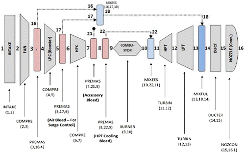
The Turbomatch program was used to develop the GT models and simulate the cycle performance of the GT models. Turbomatch is a non-commercial, in-house software developed by Cranfield University for simulating GT models of air, land and sea applications. The software is not commercialized because of its practical application in the gas turbine industry and the results obtained have a close match with 85 to 95% reality (Effiom et al., Citation2015; Nkoi et al., Citation2013a, Citation2013b; Palmer, Citation1999). The software allows the user to simulate the design and off-design performance of any gas turbine, whether existing or non-existing (Palmer, Citation1999). It basically works by dividing the engine into bricks, for example, INTAKE (a brick representing the Intake system of a gas turbine), COMPRE (a brick representing the compressor of a gas turbine), BURNER (a brick representing the combustor of a gas turbine), etc. as shown in Figure . Each brick is labeled with station vector numbers at the inlet and outlet (Pachidis, Citation2014; Palmer, Citation1999). Each brick also has station vector items such as the mass flow, total temperature and total pressure. In addition, each brick is pre-allocated with brick data items which are the specific parameters associated to that component such as the compressor pressure ratio, isentropic efficiency etc.
2.2. Simulation of the design point of the zero-staged GT model
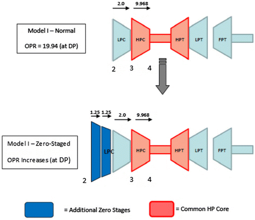
Figure shows the addition of the extra naught stages of the LP compressor to a GT model developed. Two zero stages were added so that COT will not exceed the standard limit resulting to modification of HPT cooling system and HP core design. The pressure ratio per stage for the added zero stages were considered to be 1.25 each. Hence a new overall pressure ratio of 31.15 for the whole aeroderivative engine model was achieved. A pressure ratio of 1.25 was chosen from the typical value for industrial gas turbines retrieved from the work of Yahya (Citation2011); McDougall, Cumpsty, and Hynes (Citation2012), and Al-Hamdan and Ebaid (Citation2005). This value was for each additional zero stage to the LP compressor of the GT model. Hence, an increment in the total pressure ratio of the LPC from 2.0 to 3.125 at constant isentropic efficiency of 89%.
Moreover, while keeping the HP core of the zero-staged model unaltered, COT and airflow rate of the zero staged model were obtained from Equations (1)–(4). These values were inputted to the Turbomatch program of the industrial model to simulate the design point of the zero-staged model.
Temperature ratio scaling:(1)
(1)
(2)
(2)
And,(3)
(3)
Non-dimensional mass flow scaling(4)
(4)
2.3. GT model with intercooling
Intercooling was carried out to decrease the required work input for the compression process since the OPR of 31.15 for GT is reasonably high. The intercooler was modeled between the LPC and the HPC. Room temperature intercoolants between 320 and 350 K was considered as the intercooler exit temperature, TIC,exit. An intercooler pressure loss of 2% was also assumed in the simulation due to inevitable pressure losses in an actual intercooler (Horner, Citation2007). The non-dimensional speed (N/√Tin) was kept constant since the HP shaft runs at a little lower rotational speed. The Combustor outlet temperature of the intercooled model and the corresponding flow rate of intercooled air into the HPC were obtained using Equations (5) and (6):(5)
(5)
(6)
(6)
Turbomatch code was used to simulate cycle performance of the intercooled industrial model. For the Turbomatch code, a DUCTER brick can be used as a heat exchanger. DUCTER brick was inserted between the LPC and the HPC as shown in Figure . The accessory bleed was set between stations 5 and 6, the HPT cooling bleed between 6 and 7, while the cooling flow mixer was set between 8 and 9.
2.4. GT model with reheating
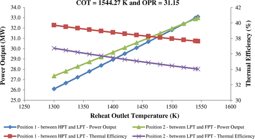
According to Cohen, Rogers, and Saravanamuttoo (Citation2009), the choice of reheating is mostly governed by the intermediate pressure between the two expansion stages. Therefore, two reheat positions were investigated and compared with only two discrete choices of reheat pressure as depicted in Figure . The reheat exit temperature investigated was between 1300 and 1500 K hence cooling was required (Walsh & Fletcher, Citation2004). The reheat combustion efficiency and the pressure loss across the reheat combustor were assumed to be 95 and 5% respectively (Lefebvre, Citation1999; Sethi, Citation2014). A DUCTER brick was also used as a heat exchanger to represent the reheater.
2.5. GT model with a combination of intercooling, reheat & recuperation
Recuperation was viable when used in conjunction with reheat and/or intercooling. This was considered to yield optimum performance. The simulation consisted of four optimum performance techniques, namely: Reheat and intercooling, intercooling and recuperation, reheat and recuperation, and also a combination of intercooling, reheat and recuperation.
HETHOT built-in brick was used as the hot side of the heat exchanger to insert a recuperator into the Turbomatch industrial model (Palmer, Citation1999). This brick was positioned at the exit of the free power. Similarly, a HETCOL brick was used as the cold side of the heat exchanger, and was positioned before the entrance to the main combustion chamber. By so doing, heat was transferred from the exhaust gas to the gas entering the combustor. About 90% recuperator heat exchanger effectiveness for both hot and cold side was assumed.
3. Result and discussion
3.1. Result of GT modeled with zero staging
Table shows the summary of the design point performance from the Turbomatch simulation for the GT with zero-staged LPC. The result for GT model without zero-staging is also presented for comparison.
Table 1. Result of zero-staged GT model at ISO compared to design point GT model without zero-staging
From Table , with the LP compressor zero-staging, the power output increased by over 49% hence the engine becomes versatile for a wider range of applications. This is due to the increase in COT and air mass flow and hence the resulting increase in fuel flow. The specific power also increased by 26%. Zero-staging increased the thermal efficiency from 38.4 to 43.2% as a result of the drop in specific fuel consumption. The fuel cost per megawatt dropped by 12.64% which could save huge amounts of money in the long run. Therefore, LP compressor zero-staging is a standard feature to be installed on all aeroderivative GT models.
3.2. Result of GT modeled with intercooling
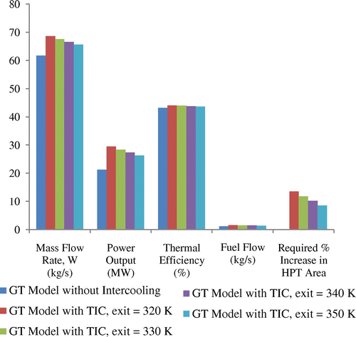
As seen from the results in Figure , when intercooling was used, the power output increased by 39% at TIC,exit = 320 K. This is because of the increased mass flow rate and higher fuel flow. As the intercooler exit temperature (TIC,exit) decreased, air flow rate and power output increased owing to more fuel needed to achieve the same fixed COT of 1544.27 K. This contributes to the increasing trend of the power output and specific power.
From Figure , despite the increase in output when intercooling was used, the fuel flow also increased and the effects compensated each other to give only a small gain in overall thermal efficiency. As TIC,exit decreased, thermal efficiency increased because the compression work required was less and hence a smaller portion of the fixed turbine work was being used to drive the compressor. However, intercooling becomes an attractive choice since both power and thermal efficiency increased and also since ≈1% increase in thermal efficiency can save millions of dollars in fuel costs in the long term.
3.3. Result of GT modeled with reheating
Figure depicts result comparison for the two reheat positions investigated in the GT model at design point with a COT of 1544.27 K and OPR of 31.15. it was observed that, having the reheat combustor between the HP turbine and the LP turbine (position 1) is the best option, since it gives higher thermal efficiency, in the order of 2–3% throughout the whole range of reheat exit temperatures. Reheat alone would not be very practical, since it reduced the thermal efficiency from 43.2 to ≈ 38% when compared with the GT model without reheat.
3.4. Effects of varying OPR on performance of various cycles and combinations
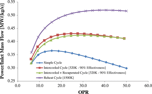
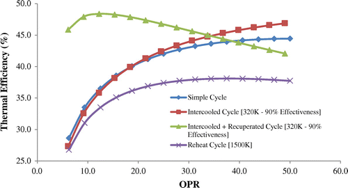
Figures and depicts sensitivity results of power output per inlet mass flow changes and thermal efficiency with varying engine OPR respectively, for the various optimized cycles and its combination at constant COT. Since recuperation alone was not possible because Texhaust < THPC,exit because the heat exchange was in the undesirable direction (reversed), a combination of intercooling and recuperation was considered, so that the THPC,exit < Texhaust.
It is seen from Figure that at fixed COT of 1544.27 K, high OPR led to lower power per inlet flow. The reheat cycle had the highest power output over the entire OPR range due to the large amount of additional fuel input in the second reheat combustor. The intercooled and intercooled + recuperation cycles resulted in similar power output owing to the little difference in Texhaust and THPC,exit and hence the effectiveness of the recuperator became low. Both cycles, however, had higher power outputs than the simple cycle because of the extra fuel required in order to achieve the same COT due to intercooling.
Reheat cycle had the worst thermal efficiency as seen in Figure , due to the excess heat energy given out by exhaust. For the intercooled cycle at low OPRs, the thermal efficiency dropped than the simple cycle since more fuel was required to achieve the same COT. However, the intercooled cycle was effective at higher OPRs since less fuel is required to achieve the same COT. Consequently, higher thermal efficiency than the simple cycle at high OPRs is achievable. The intercooled + recuperated cycle resulted in very high efficiency at low OPRs of the large difference between Texhaust and THPC,exit which raises the effectiveness of the recuperator. Thermal efficiency declined rapidly as OPR increased due the decreasing difference between Texhaust and THPC,exit.
3.5. Effects of recuperator effectiveness on the combined GT model (reheat, intercooled, and recuperated model)
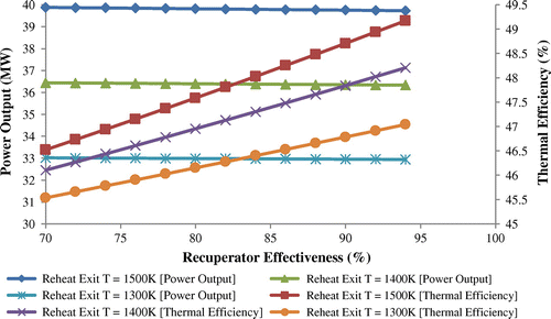
Since the recuperator effectiveness can vary depending on its design, the effects of changing the effectiveness for the GT model with reheat, recuperation and intercooling is presented in Figure . This was investigated at various reheat exit temperatures, fixed intercooler exit temperature of 320 K, OPR of 31.151, COT of 1544.28 K, and without alterations in the HP engine core.
From Figure , there were insignificant changes in the power output with varying recuperator effectiveness. This is because recuperation does not affect the turbine work or the compressor work, it is just there to reduce the amount of heat addition required in order to reach the same COT. Hence, power output remained almost constant. However, thermal efficiency increased as the recuperator effectiveness increased since more heat is being transferred from the exhaust gas to the combustor inlet. As a result of this, less fuel is needed to achieve the same COT and same power output. A combination of reheat, intercooling and recuperation models produced the optimum cycle modification on the industrial GT model derived from the commercial aircraft engine. Although, the complexity, size and costs of the engine would be high. However, combined models also resulted in the best overall performance with thermal efficiency as high as 48.7%. This is far better than the simple cycle and other less complex cycles and would save huge amounts of fuel costs over its lifetime. Hence, this is a very attractive engine model to make investments on. The power output was also as high as 39.8 MW which is suitable for high power applications. Nevertheless, it can also run at lower loads when the reheat is switched off. The high power output was as a result of low compression work due to intercooling and high turbine work due to reheat. The high thermal efficiency aroused from the huge difference between the exhaust temperature and the HP compressor exit temperature due to reheat and intercooling. Hence, recuperation became super effective.
4. Conclusion
In this study, a cycle parametric performance of various aeroderivative gas turbine was carried out to investigate the standard features that maximizes the cycle performance of aeroderivative gas turbines. The gas turbine models investigated were: Gas turbine model (GT) with LP compressor zero-staging, GT with intercooling, GT with reheating between high pressure (HP) turbine and low pressure (LP) turbine or LP turbine and free power (FP) turbine, and a GT with a combination of intercooling, reheating and recuperation. It is established from the results that:
| • | Adding two zero-stages to the LP compressor improved the power output, thermal efficiency and specific power of the aeroderivative engine by 49.6, 11.11 and 36.5% respectively. This is owing to the fact that SFC reduced by 12.6% while OPR, COT and air flow rate increased by 36, 13, and 31.4% respectively. This becomes a standard feature to be installed on all GT models derived from turbofan engines. | ||||
| • | Modelling the GT with an intercooling exit temperature of 320 K further increased power output by 39% because of the increased mass flow rate and higher fuel flow needed to achieve the same fixed COT of 1544.27 K. | ||||
| • | Also, as the intercooler exit temperature increased from 320 to 350 K, the power output dropped since fuel was needed to achieve the same fixed COT. However, at design point with a COT of 1544.27 K and OPR of 31.15, it was also established that, having the reheat combustor between the HP turbine and the LP turbine (position 1) is clearly the best option. | ||||
| • | Recuperation alone was not possible because Texhaust < THPC,exit. However, a combination of intercooling and recuperation with 90% effectiveness resulted in higher efficiency at low OPRs since THPC,exit < Texhaust. | ||||
| • | The effects of changing the regenerative effectiveness of the GT model without alterations in the HP engine core revealed that increase in recuperator effectiveness leads to an increase in thermal efficiency. | ||||
Finally, a combination of reheat, intercooling and recuperation (RH-1500 K + IC-320 K + RC) models produced the optimum cycle modification. The best overall performance was also achieved in this model, with maximized power output of 39.8 MW and thermal efficiency as high as 48.7% as compared to other GT models considered. This would save huge amounts of fuel costs over its lifetime and therefore becomes a very attractive engine model to make investments on. The power output achieved is suitable for high power applications. Nevertheless, it can also run at lower loads when the reheat is switched off.
| Nomenclature | ||
| COT | = | combustor outlet temperature (K) |
| Cp | = | specific heat capacity (kJ kg−1 K−1) |
| DP | = | design point |
| EGT | = | exhaust gas temperature (K) |
| FF | = | fuel flow (kg s−1) |
| FPT | = | free power turbine |
| GT | = | gas turbine |
| HBTE | = | high bypass turbofan engine |
| HP | = | high pressure |
| HPC | = | high pressure compressor |
| HPT | = | high pressure turbine |
| IC | = | intercooling |
| LP | = | low pressure |
| LPC | = | low pressure compressor |
| LPT | = | low pressure turbine |
| N | = | rotational speed |
| NDFC | = | non dimensional flow capacity |
| OPR | = | overall pressure ratio |
| P | = | pressure (kPa) |
| POT | = | power output (MW) |
| PR | = | pressure ratio |
| R | = | as constant of air (J kg−1 K−1) |
| RC | = | recuperation |
| RH | = | reheat |
| RPM | = | revolution per minute |
| SFC | = | specific fuel consumption (mg N−1 s−1) |
| SP | = | specific power (MW kg−1 s−1) |
| SR | = | simulated result |
| t | = | static temperature (K) |
| T | = | total temperature (K) |
| W | = | mass flow rate (kg s−1) |
| Greek symbols | ||
| γ | = | specific heat ratio |
| η | = | thermal efficiency (%) |
| ∩ | = | isentropic efficiency (%) |
| Ф | = | combustion efficiency |
| Subscripts | ||
| 0-stage | = | zero stage condition |
| exhaust | = | exhaust condition |
| HPC | = | exit high pressure compressor exit |
| HPC | = | inlet high pressure compressor inlet |
| IC | = | exit intercooling exit |
| reheat, exit | = | reheat exit condition |
Funding
The authors received no direct funding for this research.
Additional information
Notes on contributors
Samuel O. Effiom
Samuel O. Effiom obtained his MSc degree in Thermal Power (Gas turbine/aerospace propulsion) from Cranfield University, England, UK. He is currently a PhD Research student in Energy and Power engineering at Michael Okpara University of Agriculture, Nigeria. His research interests are: Thermal power propulsion systems, Renewable energy systems, CFD, exergy and environment.
Fidelis I. Abam
Fidelis I. Abam is an academic researcher and an associate professor at the Michael Okpara University of Agriculture, Nigeria. He holds a PhD degree in Energy and power technology from the University of Nigeria and a Master’s degree in thermo-fluid engineering from University of Lagos, Nigeria. His research interests are: exergy and environment, renewable energy system and power plant engineering.
Brethrand N. Nwankwojike
Brethrand N. Nwankwojike is an associate professor in the Department of Mechanical Engineering, Michael Okpara University of Agriculture, Umudike, Nigeria. He holds a PhD and MEng degree in Mechanical Engineering (Industrial and production engineering/management) from University of Nigeria. His research interests are: Engineering systems design, development, analysis/modelling and optimization.
References
- Abam, F. I., Ugot, I. U., & Igbong, D. I. (2012). Performance analysis and component irreversibilities of a (25 MW) gas turbine plant modeled with a spray cooler. American Journal of Engineering & Applied Science, 5, 35–41.
- Al-Hamdan, Q. Z., & Ebaid, M. S. Y. (2005). Modeling and simulation of a gas turbine engine for power generation. Journal of Engineering for Gas Turbines & Power, 128, 302–311. doi:10.1115/1.2061287
- Baskharone, E. A. (2006). Principles of turbomachinery in air-breathing engines. College Station, Cambridge: Texas A&M University, Cambridge University Press.10.1017/CBO9780511616846
- Bhargava, R. K., Bianchi, M., Campanari, S., De Pascale, A., Negri di Montenegro, G., & Peretto, A. (2010). A parametric thermo-dynamic evaluation of high performance gas turbine based power cycles. Journal of Engineering for Gas Turbines and Power, 132, 022001.1–022001.14.
- Bringhenti, C., & Barbosa, J. R. (2004). Methodology for gas turbine performance improvements using variable-geometry compressors and turbines. Proceedings of the Institution of Mechanical Engineers, Part A: Journal of Power and Energy, 218, 541–549.10.1243/0957650042456980
- Cohen, H., Rogers, G. F. C., & Saravanamuttoo, H. I. H. (2009). Gas turbine theory (6th ed., pp. 42–60). England: Pearson Education Ltd.
- Effiom, S. O., Abam, F. I., & Nwankwojike, B. N. (2017). Performance evaluation of aeroderivative gas turbine models derived from a high bypass turbofan engine for industrial power generation. Cogent Engineering, 4(1), 1–16. doi: 10.1080/23311916.2017.1301235
- Effiom, S. O., Abam, F. I., & Ohunakin, O. S. (2015). Performance modeling of industrial gas turbines with inlet air filtration system. Case Studies in Thermal Engineering, 5, 160–167. doi:10.1016/j.csite.2015.03.008
- Horner, M. W. (2007). Gas turbine in-line intercooler. Patent EP 0 911 505 B1, 14/02/2007 Bulletin.
- Lefebvre, A. H. (1999). Gas turbine combustion (2nd ed.). Abingdon: Taylor and Francis Publishing, USA.
- McDougall, N. M., Cumpsty, N. A., & Hynes, T. P. (2012). Stall inception in axial compressors. Journal of Turbomachinery, 112, 116–123. doi:10.1115/1.2927406
- Nkoi, B., Pilidis, P., & Nikolaidis, T. (2013a). Performance of small-scale aero-derivative industrial gas turbines derived from helicopter engines. Propulsion and Power Research, 2, 243–253.10.1016/j.jppr.2013.11.001
- Nkoi, B., Pilidis, P., & Nikolaidis, T. (2013b). Performance assessment of simple and modified cycle turboshaft gas turbines. Propulsion and Power Research, 2, 96–106. doi:10.1016/j.jppr.2013.04.009
- Pachidis, V. A. (2014). Gas turbine performance simulation. Simulation & diagnostics course notes. Cranfield: Department of power and propulsion, Cranfield University.
- Palmer, J. R. (1999). The TURBOMATCH Scheme for aero/industrial gas turbine engine design point/off-design performance calculation. SoE, User Guide. Cranfield: Department of Power and Propulsion, Cranfield University.
- Sethi, V. (2014). Gas turbine combustors, thermal power MSc course manual, Lecture. Cranfield: Department of Power and Propulsion, Cranfield University.
- Walsh, P. P., & Fletcher, P. (2004). Gas turbine performance (2nd ed.). Hoboken, NY: Blackwell Publishing, Wiley.10.1002/9780470774533
- Yahya, S. M. (2011). Turbines, compressors and fans. New York City, NY: Tata McGraw Hill Education Private Limited. ISBN 978-0-07-070702-3.

