 ?Mathematical formulae have been encoded as MathML and are displayed in this HTML version using MathJax in order to improve their display. Uncheck the box to turn MathJax off. This feature requires Javascript. Click on a formula to zoom.
Abstract
In this paper, dynamic and static structural responses of the spent nuclear fuel disposal canister for PWR due to the accidental drop and impact on to the ground are analyzed in a multidisciplinary analysis manner theoretically and numerically in order to ensure the structural durability of the canister. The impact impulse occurring by the frictionless contact collision between the canister and the ground is studied theoretically and the numerical analysis on the dynamic response is presented to compute the impact load and other dynamic features incurred during the collision. The static structural impact response occurring in the canister is also analyzed numerically using the nonlinear finite element analysis technique.
Public Interest Statement
Everybody remembers Fukushima Daiichi nuclear disaster. What is the fear? Nuclear power plant is good to us except nuclear fuel. There is no problem while nuclear fuel is inside reactor, but there happens a big problem when it burns out from reactor. How can we treat it? Atomic bomb? We cannot destroy and resolve it chemically! The spent nuclear fuel is a big trouble maker. Nowadays the only way how to treat is to seal and deposit it in a deep geological repository. This paper aims to develop a methodology how to seal and transport it into the repository safely. Specifically, this paper studies on whether a designed sealing package (or canister) of spent nuclear fuel withstands its structural integrity in a hypothetical accidental drop impact event in repository. Also this paper intends to develop a rather cheap method to solve such a problem using cheap commercial computer programs.
1. Introduction
Transportation packagings for high level radioactive wastes (HLW) such as spent nuclear fuel assemblies or radioisotopes are frequently designed as solid-walled containers and should be secured to protect the public and environment from radioactive dangers. Therefore, the main function of these solid walled containers is to provide a safe and reliable barrier against radioactivity for both normal and hypothetical accident transportation conditions. The package used to transport radioactive materials is called as a cask. The cask must be safe under normal and hypothetical accident conditions. The regulations (International Atomic Energy Agency, Citation1996) of the International Atomic Energy Agency (IAEA) provide specifications of these transport conditions. The normal conditions are hot/cold temperature environments, minimum external pressure, vibration and fatigue. The hypothetical accident conditions consist of free drop, puncture drop, and thermal conditions. The free drop condition states that the cask should maintain its structural integrity following a free drop through a distance of 9 m (30 ft) onto a flat, unyielding horizontal surface in the most vulnerable orientation. It should strike the surface in a position that is expected to inflict maximum damage and should contain the maximum weight of contents. The puncture drop condition state that the cask is required to maintain its structural integrity following a 1 m (3.25 ft) drop upon a 15 cm (6 in) diameter, at least 20 cm (8 in) long pin made of mild steel. Since the structural safety depends on the impact of hypothetical accident conditions causing maximum damage to the cask, the understanding of impact behavior of 9 m drop and the optimization for impact resistant properties are important. So far, there have been huge amount of works (Aquaro & Forassasi, Citation1983; Aquaro, Zaccari, Di Prinzio, & Forasassi, Citation2010; Choi & Seo, Citation2010; Diersch, Weiss, & Dreier, Citation1994; Lee, Kim, Kang, Chung, & Choi, Citation2004; Lee, Ryu, Kim, & Choi, Citation2005; Miller, Citation1993; Teng, Chu, Chang, Chin, & Lee, Citation2003; Teper & Suavé, Citation1989) reported on the 9 m free drop accident analysis for spent nuclear fuel (SNF) transportation, storage containers. In some of these studies, the researchers relied on very specific container geometry and they computed the peak magnitude of impact force especially in the case of plastic deformation. Consequently, their findings are limited and not necessarily applicable to other cases and furthermore they overestimated the actual effective force as the peak magnitude of the impact force because they assumed that the deformation is a perfect plastic one. In an actual drop and impact event of a container on the ground, the collision phenomena are very dynamic and occur over an extremely short period of time. As a result, the peak magnitude of the impact load is extremely high. It is critically important to determine the actual effective impact force which might be exerted on a canister during such an impact period for the structural analysis to determine the strength of the container if its structural durability design is to be sufficiently improved. A static structural analysis is carried out to determine the strength of the container and in this case the actual effective impact force to be exerted on the container is crucial for the proper reliable analysis.
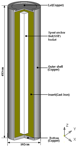
Nowadays Korea operates a total of 21 nuclear power plants. Seven more nuclear power plants will be constructed by 2020.This construction of nuclear power plants will increase the generation of a significant amount of radioactive wastes such as spent nuclear fuels. The estimated total amount of SNF from all 28 nuclear power plants will be approximately 36,000 tons of Heavy Metals (THM) (Choi, Kim, & Kang, Citation1999). The safe isolation of nuclear wastes or radioisotopes from the human environment and biosphere is a critical issue to maintain the continuing construction of nuclear power plants. Since SNF emits heat and much radiation, careful treatment of SNF is required. For this reason, a long term (usually, 10,000 years) safe repository for SNF disposal should be secured. Deep geological repositories have been considered as the most feasible and safe solutions to protect the public health and environment from the radiological effects caused by nuclear waste during its harmful period (Chijimatsu et al., Citation2005; Kwon, Citation2010; Lee, Cho, Choi, & Choi, Citation2007; Zhou, Apted, & Kessler, Citation2010). Currently, deep geological disposal technology involves depositing SNF at a mined underground facility located at 500–1000 m below ground level in a rock encased location. Some countries are pursuing R&D projects to develop deep geological disposal technologies for SNF that will be commercially viable by 2020 (Cho et al., Citation2008). Korea began a national R&D program to develop deep geological disposal technology for HLW such as SNF. Research studies for the development of the engineered barriers were carried out using a Korean calcium bentonite block as a buffer material, and the Korean SNF disposal canister or KDC for PWR spent fuels was designed as shown in Figure (Lee et al., Citation2007). Here, the term “canister” is defined as a container or a specific cask which is designed to encapsulate SNF bundles (or baskets) at a hypothetical deep geological repository and transported to the borehole by a specially designed vehicle in the repository. Hence, the canister may be one of casks. As shown in Figure , the conceptual design of the KDC has a cylindrical shape and consists of a massive insert with corrosion resistant outer shell, lid and bottom. The insert provides mechanical strength and radiation shielding, allowing four square tube shaped SNF baskets (assemblies) to be contained and fixed configuration. The SNF disposal canister for PWR should be able to withstand the geo-environmental conditions for period of 10,000–1,000,000 years at a depth of 500 m in an underground repository. For this purpose, the SNF disposal canister must have sufficient structural integrity (Kwon & Choi, Citation2003; Kwon, Kang, Choi, & Kang, Citation2001) and light enough weight (Wang, Gea, & Kwon, Citation2014) for easy handling and cheap manufacturing while maintaining radioactive shielding. However, whether this conceptually designed canister as shown in Figure has sufficient structural integrity to withstand hypothetical accident transportation conditions, especially 9 m free drop impact condition is still questionable. Since a drop down collision is especially dynamic, large-plastic deformations in canister may be produced. Due to the costly nature of material, environmental and human consequences, the dynamic and static structural responses of a container like the SNF disposal canister for PWR which is now operated in Korea subject to an accidental ground drop and impact event should be analyzed at the design stage. This will help determine whether the canister structure has sufficient impact strength to ensure a low probability of severe collision damage. The accidental ground drop and impact event experienced by the canister may cause a damage and fracture of the canister which will expose the radioactivity to the human environment. Of particular concern to the structural designer is determining the actual effective impact force which might be exerted on the canister for the structural analysis during such an impact and can cause the collapse of the canister. The impact force applied to the canister is very dynamic (Kwon, Citation2013, Citation2016), whereas the resulted final structural damage or deformation occurring in the canister is static (Kwon, Citation2011). The collision impact problem is a typical crucial one treated by many people (Brach, Citation1991; Goldsmith, Citation1960; Stronge, Citation2000). Also many researchers tried to compute the impact force pulse due to contact collision between two bodies analytically, numerically and experimentally (Hunter, Citation1957, Citation1960; Jaeger, Citation1994; Maw, Barber, & Fawcett, Citation1976; Wang & Mason, Citation1992; Zhong & Jaroslav, Citation1994). However, the three dimensional analytical solution for the impact force is quite difficult to obtain except for a simple one or some two dimensional solutions assuming the colliding bodies as particles or spheres. The collision impact phenomenon of a SNF disposal canister for PWR subjected to an accidental drop and impact on the ground is quite complicated and a multidisciplinary one. Hence, a multidisciplinary analysis is needed to understand the phenomenon. A dynamic response should be analyzed to compute the impact force pulse occurring and applied to the canister during collision impact period. Simultaneously, a static structural response should be analyzed to compute the stresses and deformations occurring in the SNF disposal canister due to the impact force. However, a simultaneous multidisciplinary analysis is a time-consuming tedious hard work because there may exist so many situations of accidental drop and impact events on the ground. Therefore, previously, only a static structural analysis (Kwon, Citation2011) for the SNF disposal canister was performed to compute the stresses and deformations occurring in the canister due to the accidental drop and impact on the ground but the applied impact force was not accurate because of the unskilled treating of the CAE system of RecurDyn. Hence, a separate dynamic analysis (Kwon, Citation2013) was performed to compute the impact force pulse accurately occurring and applied to the SNF disposal canister during the collision impact period and revealed many interesting dynamic characteristics of the impact force. Furthermore, a theoretical and numerical methodology (Kwon, Citation2016) was proposed to compute the impact impulse which can be applied specifically to the SNF disposal canister subjected to the accidental drop and impact on the ground. In the previous study (Kwon, Citation2016), the numerically computed impact impulses were compared with those obtained by the theoretically developed method and they agreed very well. Nonetheless, a simultaneous multidisciplinary analysis is still desirable despite its time-consuming tedious hard work. The only tool for this work is using the explicit time integration solvers, or the 3-D dynamic simulation analysis code such as LS-DYNA3D and ABAQUS/Explicit (Lee et al., Citation2005). Even though these 3-D dynamic simulation analysis using commercial FEA codes is the most efficient method, the cost is very high because commercial 3-D dynamic simulation analysis codes are very expensive. LS-DYNA3D or ABAQUS/Explicit is rarely available to researchers. But rather somewhat cheap commercial codes like RecurDyn, ADAMS, and NISA are easily available. Moreover, LS-DYNA3D and ABAQUS are more suitable to the crash between automobiles because surface contact usually occurs and friction effect may be very significant in such a case, whereas the contact of the canister onto the ground is a point or a line contact in the accidental drop and impact event from the transportation vehicle in the repository and the friction effect may not be significant or serious in such a case. Therefore, a cheaper or economic methodology for the analysis of the dynamic and static structural responses of the SNF disposal canister using commercial CAE codes (RecurDyn, ADAMS, NISA) is developed and the theoretical study of the impact impulse is carried in this paper. However, in future studies, 3-D dynamic simulation analysis will be carried out using commercial explicit time integration solvers like LS-DYNA3D and ABAQUS/Explicit. Therefore, in this study using commercial CAE codes of RecurDyn, ADAMS, and NISA instead of LS-DYNA3D and ABAQUS/Explicit, dynamic and static structural responses of the canister are analyzed simultaneously together in a multidisciplinary analysis manner in order to better understand collision impact phenomena of a SNF disposal canister for PWR subjected to an accidental drop and impact on the ground and to ensure the structural durability of the canister. Besides, a general method to compute the impact impulse occurring due to the frictionless contact condition between canister with general geometric shape not limited to the cylindrical shape and ground is developed theoretically in this study. This theoretical method is the generalization of the method theoretically developed in the previous study (Kwon, Citation2016) in which only the specific cylindrical shape of canister could be applied. The comparison between the theoretical solution and the numerical solution for the impact impulse is not presented in this study because it was treated and verified in the previous study (Kwon, Citation2016). Numerical dynamic response analyses to compute impact forces (and impact impulses), velocities, and altitudes of the canister due to the collision impact on to the ground were performed using commercial CAE codes of RecurDyn and ADAMS. Numerical structural static response analysis to compute stresses and deformations occurring in the canister due to the collision impact was performed using the nonlinear analysis capability of commercial FEA code, NISA. Although it cannot be treated in detail in this study, the structural optimization design (Liu et al, Citation2016; Zhou & Wang, Citation2014) of the canister should be performed after the structural response analysis is completed, especially the design considering uncertainties (like load uncertainties etc.) included in the accidental drop and collision impact event of the SNF disposal canister on to the ground.
2. Dynamic response analysis
In this section, the dynamic response analyses are presented and especially a general theoretical method to compute impact impulse occurring due to the frictionless contact between canister with arbitrary general geometric shape and ground is developed.
2.1. Theoretical impact impulse analysis
2.1.1. Derivation of impact impulse equation for collision between two moving bodies
When a collision occurs between two moving bodies, they experience discontinuous changes in both velocity and angular velocity. The actual physical phenomena and transformational processes during the impact are highly complex. In terms of behavior in the bodies affected, it is postulated that the impact itself occurs in such a short time interval ∆t that in the mathematical description the idealization ∆t → 0 is possible. This implies that any wave of deformation or stress throughout the bodies is negligible during impact since such processes require finite periods of time. Hence, all bodies of a system may be treated as rigid bodies in the event of a collision (Wittenburg, Citation2007). During the infinitesimally short time interval, the positions and angular orientations of the bodies remain unchanged because the velocities and angular velocities themselves remain finite. Only impulsive forces can cause discontinuous changes in velocity and angular velocity. As such, force F(t) is called an impulsive force if its integral over the time interval ∆t converges toward a finite quantity when ∆t approaches zero. This can be expressed as,
(1)
(1)
It should be noted that for this to be the case, the magnitude of F(t) must tend towards infinity during ∆t in the case ∆t → 0. Also, the quantity may be referred to as the impulse while the torque of the impulse is termed the impulse couple.
Let us consider a moving body which collides with another moving body. At the point of impact located by the vector , the impulsive force F is acting on each body. Both Newton’s law and Euler’s law of motion suggest
(2)
(2)
where r is the position vector of the mass center of the colliding body with respect to the inertial reference point, is the position vector of the collision contact point with respect to the mass center of the body, m is the mass of the body,
is the inertia tensor of the body with respect to the mass center C, and
is the angular velocity of the body. Both Newton’s and Euler’s equations are integrated over the time interval ∆t. When ∆t goes to zero, the tensor
and the vector
have constant coordinates in inertial space. Also the finite term
does not contribute to the integral. Therefore, the resulting equations read
(3)
(3)
Let us consider a collision between two arbitrary bodies as shown in Figure . To obtain a solution, a proper global inertial coordinate system must first be chosen. For the purpose of this study, a global inertial rectangular coordinate system (x, y, z) is selected and presented in Figure . The origin O is located at the colliding contact point between two rigid bodies. The x axis is positioned in the perpendicular direction with respect to the colliding contact plane of the two bodies, while the y and z axes are positioned in the tangential directions with respect to the colliding contact plane of the two bodies. It is important to note that the colliding contact plane is the y-z plane. Therefore as shown in Figure . Given these conditions, Equation in (3) can be adjusted as
(4)
(4)
Figure 2. A coordinate system where i, j, k are orthonormal unit vectors and collision between two moving bodies.
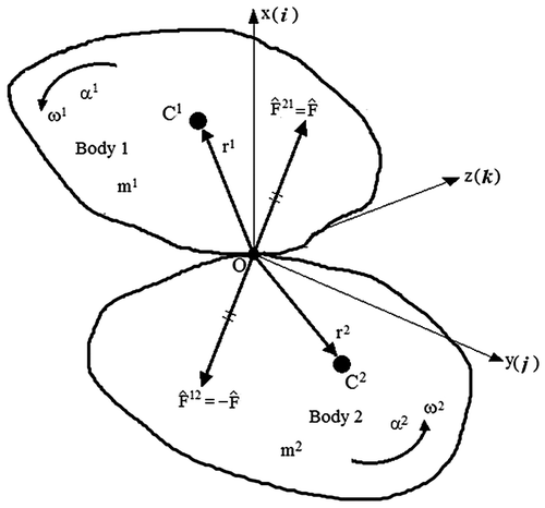
Therefore the velocity of the colliding contact point O (or ) is found to be related to the mass center velocity v as
(5)
(5)
In this regard, once the velocity of the mass center is obtained, the velocity of the colliding point can be obtained by Equation (Equation5(5)
(5) ). Moreover, using the notation shown in Figure , Equation in (4) may be transformed as
(6)
(6)
In these cases, v and ω indicate the velocity and the angular velocity respectively immediately before the collision, while c and Ω denote the velocity and the angular velocity respectively immediately after the collision. Then, Equations in (6) take the following forms, noting (7)
(7)
(8)
(8)
(9)
(9)
These equations essentially represent linear momentum and angular momentum conservation laws as stated in Equation (Pestel & Thomson, Citation1968). Using Equation (Equation5(5)
(5) ), with e ≡ the coefficient of restitution, the condition of restitution takes the following form,
(10)
(10)
Based on this information, ten scalar equations from Equations (Equation7(7)
(7) )–(10) may be generated though there exist twelve unknown variables for the solution. Subsequently, two more equations are needed to obtain the two remaining unknown variables. These additional two equations may be obtained from examining the collision contact conditions.
2.1.2. Impact impulse solution for frictionless collision contact
Usually the softness and friction of ground, or floor play a crucial role in determining the actual impulse. However, if the friction coefficient is taken into account, the mathematical analysis quite complicate and lengthy. Furthermore, the contact between the canister and the ground is a point contact or a line contact. In this case the effect of friction may be negligible comparing to the surface contact occurring in the automobile crash. Therefore, even though the analysis with frictional hard contact condition is desirable practically, such a case will be treated in future studies because this paper aims to suggest the mathematical methodology how to formulate the impact impulse theoretically. Hence, a collision case is considered in which there is no friction between two colliding bodies. In this case, the frictionless contact condition is valid and takes the following form,(11)
(11)
when the notation in Figure is adopted. Equation (11) provides missing additional equations for the solution. These equations can be solved directly in order to obtain the closed form impact solutions. Using the rectangular coordinate system (x, y, z) as shown in Figure , noting (i = 1, 2), the general solution for impact impulse may be obtained as
(12)
(12)
and (13)
(13)
where superscript “i = 1, 2” means two moving bodies as shown in Figure .
When the coordinate system (i = 1, 2) is a principal coordinate of each body (i), Equation (12) can then be expressed as, noting that
and
from (5),
(14)
(14)
Given this information, the impact impulse is found to be proportional to the relative velocity of the colliding contact points. It should be noted that the impact impulse is large when the masses of the two colliding bodies are also large so long as their centers of mass are located near the impact normal which is the straight line (i.e. the x axis in Figure ) perpendicular with respect to the colliding contact plane (i.e. the y-z plane in Figure ). The plane is tangential and common to both bodies at their point of contact. In addition, the impact impulse reaches its maximum value when the impact normal passes through the centers of mass and when the velocities of the centers of mass coincide immediately before impact with the impact normal. This constitutes a straight central direct collision impact.
2.1.3. Justification through classical theory
The velocity of the body’s mass center and the angular velocity of the body also satisfy the energy conservation law during free drop test such that(15)
(15)
with (potential energy of the body).
In this case, v is the velocity of the body’s mass center, ω is the angular velocity of the body, g is the magnitude of the gravitational acceleration, and h is the height of the body’s mass center from the ground. If the body drops freely with zero initial velocity and without any rotation from the place whose vertical altitude (height) is H from the ground, then the velocity of the body’s mass center immediately before the collision can be obtained as and
from (15). In doing so, it is important to note that the ground surface coincides with the colliding contact plane that is tangential and common to both the drop body and the ground at their point of contact. By inserting this velocity value into (12), the impact impulse at the moment of the collision can be determined. If the body drops vertically on to the ground or if the impact normal (i.e. the x axis) of the colliding contact plane passes through the drop body’s mass center (i.e. y and z = 0 in (12)) (i.e. a straight central direct impact), then (12) takes the following form
(16)
(16)
where H′ is the altitude (or height) which the canister reaches after the collision. This agrees precisely with the classical theory derived by Pestel and Thomson (Citation1968) when a canister is treated as a particle with mass m as it strikes against the wall. Also, the formula for Equation (12) derived in this paper precisely agrees with that formulated by Wittenburg (Citation2007). Hence, the impact impulse in (12) is justified through the classical theory. Moreover, it is clear that the drop body’s mass, velocity of the drop body’s mass center, the angular velocity of drop body, the position of the drop body’s mass center, and the moments and products of inertia for the drop body with respect to its mass center affect the impact impulse as shown in (12). Furthermore, the impact impulses formulated theoretically in (12) and (16) are applicable to any type of drop body geometry or collision.
2.1.4. Application to the SNF disposal canister accidentally dropped and impacted on the ground
The general solution derived in the previous section is applied to the SNF disposal canister accidentally dropped on the ground as shown in the Figure . The canister has a cylindrical geometry which has dimensions shown in the Figure . If the colliding contact between the canister and the ground is assumed to be frictionless, then the impact solutions formulated in (12) can be applied to the accidental drop and ground impact event for a SNF disposal canister. If the canister is taken as body 1 and the ground as body 2 from the Figure , then the mass of the ground can be assumed to be infinitely very large and the velocity of the ground to be zero. Hence, previous terms regarding ground (body 2) can be removed from the general solution Equations (12)–(13). The total impact impulse applied to the canister during impact period (T) due to the collision between the canister and the ground can thus be obtained from Equations (12)–(13) as(17)
(17)
Figure 3. Collision between the SNF disposal canister and the ground. An inertial global coordinate system (x, y, z) is chosen for the analysis.
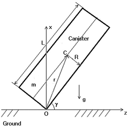
and ,
where m is the canister’s mass, v is the velocity of the canister’s mass center, is the angular velocity of the canister, y and z are coordinates of the canister’s mass center, e is the coefficient of restitution, and
is the inertia tensor of the canister with respect to the canister’s mass center immediately before the collision or at the moment of collision. The above Equation (17) agrees exactly with the result presented in the previous work (Kwon, Citation2016). Therefore, the equations formulated in this work treat the more general case which can be used to the wide range applications. Using (17) the impact impulse for any canister geometry can be computed even though the current geometry of canister is cylindrical. The three dimensional form of impact impulse for the specific geometric canister shown in the Figure can be derived using (17). Let us assume that the cylindrical canister is one dimensional cylindrical beam whose length is L and diameter is R and L ≫ R or R/L ≈ 0. Then the position vector, r = xi + yj + zk, of the mass center C becomes r ≈ (L/2)(sin γi + cos γk), that is, x, y, and z from the general solution (17) become x ≈ (L/2) sin γ, y = 0, z ≈ (L/2) cosγ for one dimensional cylindrical beam. And the components of inertia tensor
with respect to the mass center C in terms of the current coordinates x, y, z become
(18)
(18)
The impact velocity and angular velocity can be assumed as(19)
(19)
Inserting y = 0, , and (19) into the total impact impulse solution (17), the impact impulse for the thin long canister becomes
(20)
(20)
Finally, inserting and
into the above (20), the total impact impulse becomes for the very thin long cylindrical canister or one dimensional uniform beam (or rod),
(21)
(21)
This impact impulse for the one dimensional prismatic uniform beam dropped on to the ground agrees exactly with the result derived in the case of drop/impact analysis of one dimensional uniform beam by Zhou et al. (Citation2008). Zhou et al. (Citation2008) derived a relationship between the impact impulse P(T) and the impact angle (γ) for drop/impact analysis of typical portable electronic devices assuming the portable electronic device as one-dimensional uniform beam (or rod) as shown in Figure . Denoting the overall mass by m, the length by l, the initial impact velocity by V0, the drop/impact orientation by γ, and the contact-impact period by T, they firstly derived the rebound vertical velocity V⊥A (T) of contact point A of the beam-rod system in Figure as follows,(22)
(22)
Figure 4. Sketch of a beam-rod system for drop/impact analysis of electronic device in Zhou et al. (Citation2008).
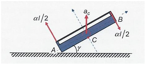
Denoting the coefficient of restitution by ξ, then the rebound velocity is V⊥A (T) = ξV0. Thus they secondly derived a relationship between the impulse and the impact angle as follows,(23)
(23)
which exactly agrees with the impact impulse in (21) derived in this paper noting that e = ξ, .
2.2. Numerical analysis of dynamic responses
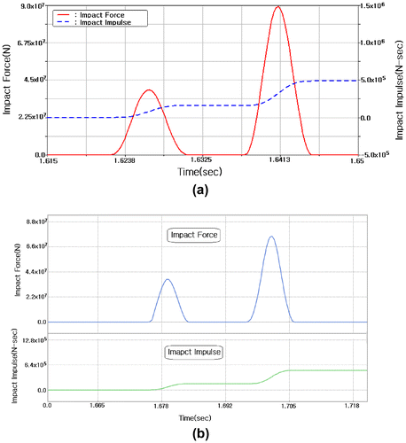
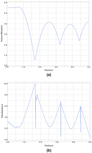
In this section the numerical dynamic response analysis is presented. The three dimensional analysis is carried out to compute the impact force pulse during collision using the commercial computer dynamic analysis codes, ADAMS and RecurDyn, and both results are compared. And the impact forces computed in this section are used as the external loads for the following structural static response analysis in a multidisciplinary analysis manner. In order to perform the computer dynamic simulation of the accidental drop and ground impact event for a SNF disposal canister transported to a repository, the vehicle, the canister and the ground are modelled together in which the canister stayed on the vehicle whose height is 5 m (see Figure ). The vehicle is moving with a speed and thereafter the canister dropped from the vehicle as shown in Figure . Figure shows the dynamic computer simulation process that the canister drops from the vehicle and collides on to the ground. Figures and show the dynamic response analysis results. Figure show the impact force and impact impulse when the canister collides on to the ground. According to the analysis result, the canister’s top or bottom hits the ground firstly and then the opposite part hits the ground secondly very shortly after the first collision. The second impact force is larger than the first one. Two analysis results carried out by ADAMS and RecurDyn agree very well as shown in Figure . Figure shows variations of vertical altitude and velocity of the canister (mass center) during the dynamic simulation duration of the SNF disposal canister in an accidental drop and ground impact event.
Figure 5. The computer dynamic simulation process of the SNF disposal canister dropped accidentally and impacted on to the ground (a) Canister on the vehicle’s top surface, (b) Canister drop from the vehicle and (c) Canister collision on to the ground.

3. Numerical analysis of static responses
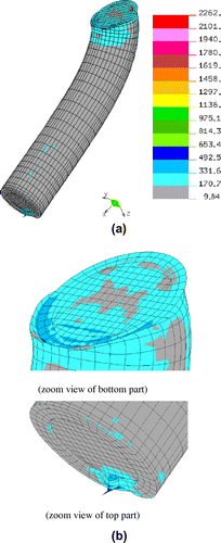
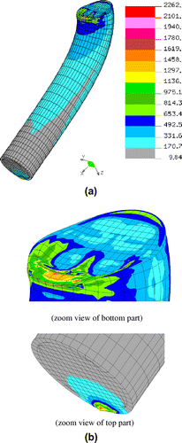
Even though the collision phenomenon of the SNF disposal canister subjected to the accidental drop and impact on to the ground is dynamic and the structural deformation characteristics during impact may be vibration, the final structural damage or deformation incurred to the canister by the collision impact is static as seen in the previous study (Kwon, Citation2011). The static structural damage is caused mainly by the impact load. In this section the static structural response such as structural damage or deformation of the canister due to the impact force is analyzed using the commercial finite element computer analysis code, NISA. The impact forces computed thru the previous dynamic response analyses are applied to the canister as the external loads in a multidisciplinary analysis manner. A nonlinear structural analysis is carried out to compute stresses and deformations occurring in the canister using the nonlinear analysis capability of NISA. Figure shows the structural shape and components of the SNF disposal canister used for the analysis. Tables and show the material property values which were used in Kwon (Citation2011) and Börgesson (Citation1992) of the component parts of the canister which are used for the nonlinear structural analysis. The peak magnitude of impact force computed thru the previous dynamic response analyses and applied to an edge point of the canister’s top due to the first collision impact as shown in Figure is . The coordinates of the contact edge point is x = −0.51 m, y = −0.01 m, z = 4.83 m. The bottom surface is constrained to prevent the rigid body motion. Using the material property values shown in Table (Börgesson, Citation1992), a nonlinear elastoplastic structural analysis is carried out. Figures and show the static structural response of damaged or deformed shape of the canister due to the impact loads applied to the canister during the accidental drop and ground impact. The canister is severely damaged or deformed by the peak magnitude of impact force as shown in Figures and . Examining the stresses occurring in the cast iron insert of the canister, the maximum stress occurring in the cast iron insert exceeds severely the yield stress, whereas the deformation is not so much seriously large enough to reveal the SNF bundles sealed inside the canister, when the peak magnitude of the impact force is applied as an impact load as shown in Figure .
Table 1. Material property values used for the analysis
Table 2. Piecewise linear hardening stress-strain curve data used for the analysis
4. Conclusion
In this paper, the dynamic and static structural responses experienced by a SNF disposal canister subjected to an accidental drop and ground impact event were analyzed theoretically and numerically. Given the consequences in material, environmental and human costs should such an accident occur, the dynamic and static structural collision response of a container like the Korean Disposal Canister (KDC) for PWR should be carefully analyzed at the design stage in order to ensure that its impact strength can withstand a severe collision. Of primary concern to the designer of such a SNF disposal canister is determining the actual effective force exerted on the canister during the impact as an external load. A theoretical mathematical study to compute the impact impulse was presented and simultaneously the dynamic response was analyzed numerically using the commercial computer codes, RecurDyn and ADAMS. Simultaneously, a static structural response was analyzed to determine the structural strength of the canister in a multidisciplinary analysis manner. The static structural response analysis was carried out using the commercial finite element analysis computer code, NISA. A nonlinear elastoplastic structural analysis was performed for the peak magnitude of impact force. The dynamic analysis result shows that shortly after the first collision of the canister on to the ground the second collision occurs and the second impact force is larger than the first one. The static structural response analysis result shows that the canister is severely damaged or deformed for the peak magnitude of the impact force but the SNF bundles sealed inside the canister are not revealed.
| Nomenclature | ||
| = | Impact impulse components | |
| = | Position | |
| = | Velocity | |
| = | Angular velocity | |
| = | Coefficient of restitution | |
| = | Mass | |
| = | Inertia tensor | |
| = | Cartesian coordinates | |
| = | Time | |
| = | Energy | |
| γ | = | Colliding angle |
Funding
This work was supported by 2016 Hongik University Research Fund.
Cover image
Source: Author.
Additional information
Notes on contributors
Young Joo Kwon
Young Joo Kwon received his BS and MS degrees in Mechanical Engineering from Seoul National University in 1979 and 1981 respectively. He then received his PhD degree from the Department of Aerospace Engineering at the University of Michigan at Ann Arbor in 1987. He worked as an engineer at ADAPCO and EMRC in USA, and as a senior researcher at KIST in Korea. He is currently a Professor at the Department of Mechanical & Design Engineering at Hongik University in Korea. His research interests include nonlinear solid mechanics and structural analysis, multibody dynamics, FEM, structural optimization, and collision impact. He has studied on the spent nuclear fuel disposal canister development since 2000. This paper is one of outcomes from these studies. He had involved in the national project sponsored by Korean government and worked with KAERI for the high level radioactive waste treatment such as spent nuclear fuel.
References
- Aquaro, D., & Forassasi, G. (1983). Impact tests on scale models of a shock absorber for LWR spent fuel transport packaging. In 7th International Conference on Structural Mechanics in Reactor Technology. Chicago, IL.
- Aquaro, D., Zaccari, N., Di Prinzio, M., & Forasassi, G. (2010). Numerical and experimental analysis of the impact of a nuclear spent fuel cask. Nuclear Engineering and Design, 240, 706–712.10.1016/j.nucengdes.2009.12.018
- Börgesson, L. (1992). Interaction between rock, bentonite buffer and canister. FEM calculations of some mechanical effects on the canister in different disposal concepts (p.83 + appendixes, Technical report TR 92-20). Stockholm: Swedish Nuclear Fuel and Waste Management. ISSN 0284-3757.
- Brach, R. M. (1991). Mechanical impact dynamics: Rigid body collisions. New York, NY: John Wiley & Sons.
- Chijimatsu, M., Nguyen, T. S., Jing, L., De Jonge, J., Kohlmeier, M., Millard, A., … Sugita, Y. (2005). Numerical study of the THM effects on the near-field safety of a hypothetical nuclear waste repository—BMT1 of the DECOVALEX III project. Part 1: Conceptualization and characterization of the problems and summary of results. International Journal of Rock Mechanics & Mining Sciences, 42, 720–730.10.1016/j.ijrmms.2005.03.010
- Cho, H. J., Lee, J. Y., Cho, D. K., Kim, S. K., Kim, S. S., Kim, K. Y., …Lee, J. O. (2008). Korean reference HLW disposal system (KAERI /TR-3653/2008). Korea: Korea Atomic Energy Research Institute.
- Choi, J. W., Kim, W. J., & Kang, C. H. (1999). Reference spent fuel and its characteristics for a deep geological repository concept development. Journal of the Korean Nuclear Society, 31, 23–38 [in Korean].
- Choi, W. S., & Seo, K. S. (2010). A simple sizing optimization technique for an impact limiter based on dynamic material properties. Nuclear Engineering and Design, 240, 925–932.10.1016/j.nucengdes.2009.12.008
- Diersch, R., Weiss, M., & Dreier, G. (1994). Investigation of the impact behaviour of wooden impact limiters. Nuclear Engineering and Design, 150, 341–348.10.1016/0029-5493(94)90153-8
- Goldsmith, W. (1960). Impact: The theory and physical behavior of colliding solids. London: Edward Arnold.
- Hunter, S. C. (1957). Energy absorbed by elastic waves during impact. Journal of the Mechanics and Physics of Solids, 5, 162–171.10.1016/0022-5096(57)90002-9
- Hunter, S. C. (1960). The Hertz problem for a rigid spherical indenter and a viscoelastic half-space. Journal of the Mechanics and Physics of Solids, 8, 219–234.10.1016/0022-5096(60)90028-4
- International Atomic Energy Agency. (1996). IAEA safety standards series No. ST-1, Regulations for the safe transport of radioactive material.
- Jaeger, J. (1994). Analytical solutions of contact impact problems. Applied Mechanics Reviews, 47, 35–54.10.1115/1.3111070
- Kwon, Y. J. (2010). Finite element analysis of transient heat transfer in and around a deep geological repository for a spent nuclear fuel disposal canister and the heat generation of the spent nuclear fuel. Nuclear Science and Engineering, 164, 264–286.10.13182/NSE09-11
- Kwon, Y. J. (2011). Structural analysis of PWR (pressurized water reactor) canister for applied impact force occurring at the moment of falling plumb down collision. Journal of the Computational Structural Engineering Institute of Korea, 24, 211–222 [in Korean].
- Kwon, Y. J. (2013). Rigid body dynamic analyses on the spent nuclear fuel disposal canister under accidental drop and impact to the ground: Numerical analysis. Journal of the Computational Structural Engineering Institute of Korea, 26, 373–384 [in Korean].10.7734/COSEIK.2013.26.5.373
- Kwon, Y. J. (2016). Theoretical and numerical computation of impact impulse due to frictionless collision experienced by a spent nuclear fuel disposal canister accidentally dropped on the ground. Journal of Mechanical Science and Technology, 30, 637–642.10.1007/s12206-016-0117-6
- Kwon, Y. J., & Choi, J. W. (2003). Finite element stress analysis of spent nuclear fuel disposal canister in a deep geological repository. JSME International Journal Series A, 46, 543–549.10.1299/jsmea.46.543
- Kwon, Y. J., Kang, S. W., Choi, J. W., & Kang, C. H. (2001). Structural analysis for the determination of design variables of spent nuclear fuel disposal canister. KSME International Journal, 15, 327–338.10.1007/BF03185216
- Lee, J., Cho, D. K., Choi, H. J., & Choi, J. W. (2007). Concept of a Korean reference disposal system for spent fuels. Journal of Nuclear Science and Technology, 44, 1565–1573.10.1080/18811248.2007.9711407
- Lee, Y. S., Kim, H. S., Kang, Y. H., Chung, S. H., & Choi, Y. J. (2004). Effect of irradiation on the impact and seismic response of a spent fuel storage and transport cask. Nuclear Engineering and Design, 232, 123–129.10.1016/j.nucengdes.2004.05.001
- Lee, Y. S., Ryu, C. H., Kim, H. S., & Choi, Y. J. (2005). A study on the free drop impact of a cask using commercial FEA codes. Nuclear Engineering and Design, 235, 2219–2226.10.1016/j.nucengdes.2005.03.009
- Liu, J., Wen, G., & Xie, Y. M. (2016). Layout optimization of continuum structures considering the probabilistic and fuzzy directional uncertainty of applied loads based on the cloud model. Structural and Multidisciplinary Optimization, 53, 81–100.10.1007/s00158-015-1334-9
- Maw, N., Barber, J. R., & Fawcett, J. N. (1976). The oblique impact of elastic spheres. Wear, 38, 101–114.10.1016/0043-1648(76)90201-5
- Miller, G. K. (1993). Calculation of impact loads for high energy drops of cylindrical containers. International Journal of Impact Engineering, 13, 511–526.10.1016/0734-743X(93)90083-J
- Pestel, E. C., & Thomson, W. T. (1968). Dynamics. McGraw-Hill Book Company.
- Stronge, W. J. (2000). Impact mechanics. Cambridge: Cambridge University Press.10.1017/CBO9780511626432
- Teng, T. L., Chu, Y. A., Chang, F. A., Chin, H. S., & Lee, M. C. (2003). The dynamic analysis of nuclear waste cask under impact loading. Annals of Nuclear Energy, 30, 1473–1485.10.1016/S0306-4549(03)00080-X
- Teper, W. W., & Suavé, R. G. (1989). Simplified method for predicting impact loads of solid-walled transportation packagings for radioactive materials. Journal of Pressure Vessel Technology, 111, 316–321.
- Wang, B., Gea, H. C., & Kwon, Y. J. (2014). Finite element analysis of stresses and deformations occurring in the spent nuclear fuel (SNF) disposal canister deposited in a deep geological repository. Nuclear Engineering and Design, 266, 166–179.10.1016/j.nucengdes.2013.10.030
- Wang, Y., & Mason, M. T. (1992). Two-dimensional rigid-body collisions with friction. Journal of Applied Mechanics, 59, 635–642.10.1115/1.2893771
- Wittenburg, J. (2007). Dynamics of multibody systems (2nd ed.). New York, NY: Springer.
- Zhao, J., & Wang, C. (2014). Robust structural topology optimization under random field loading uncertainty. Structural and Multidisciplinary Optimization, 50, 517–522.10.1007/s00158-014-1119-6
- Zhong, Z. H., & Jaroslav, M. (1994). Contact-impact problems: A review with bibliography. Applied Mechanics Reviews, 47, 35–54.
- Zhou, C. Y., Yu, T. X., & Lee, R. S. W. (2008). Drop/impact tests and analysis of typical portable electronic devices. International Journal of Mechanical Sciences, 50, 905–917.10.1016/j.ijmecsci.2007.09.012
- Zhou, W., Apted, M. J., & Kessler, J. H. (2010). The thermal-hydrological impact on increased spent-fuel storage capacity in yucca mountain repository. Nuclear Technology, 170, 336–352.10.13182/NT10-A9487

