
 ?Mathematical formulae have been encoded as MathML and are displayed in this HTML version using MathJax in order to improve their display. Uncheck the box to turn MathJax off. This feature requires Javascript. Click on a formula to zoom.
Abstract
Predictive Torque Control (PTC) is an acceptable alternate to Direct Torque Control (DTC) of induction motors. The limitation of classical PTC is selection of weighting factor, improper selection of weighting factors lead to distortions in current, voltage, high torque and flux ripple. In classical PTC, to reduce torque and flux ripples manual tuning of weighting factors is needed and weighting factors are selected empirically. To circumvent tedious tuning process of weighting factor, this article proposes a new self-tuned PTC algorithm to Open End Winding Induction Motor (OEWIM) drive. OEWIM’s are more popular in electric vehicles, ship propulsion but they require ripple free torque. A new self-tuned PTC algorithm is implemented to OEWIM with multi-level inversion to reduce torque and flux ripples. The effectiveness of proposed PTC algorithm was tested by applying it to multi-level inverter fed OEWIM drive through simulation and experimental verification.
Public Interest Statement
The variable speed drives are became more popular in industries. The Variable speed drives (VSD) generally employed with induction motors. Nowadays, PTC and DTC schemes are most popular for VSD’s. PTC and DTC of induction motor drives suffer from higher ripple in torque and flux. OEWIM fed with multi-level inversion is a better alternate to reduce torque and flux ripples. The PTC of OEWIM is an interesting research area, since it has own features: it provides multi-level inversion, lower ripple in torque and flux, less current distortions, faster dynamic response, easy inclusion of constrains in cost function. This article gives the limitations of DTC and PTC and introduces an algorithm to eliminate tedious tuning process involved in implementation of PTC. This article helps the researchers toward the implementation PTC of multi-lever inverter fed OEWIM drives.
1. Introduction
Open-end winding induction motors are used in ship propulsion, hybrid electric vehicles and renewable energy interfacing. The speed control of OEWIM drives can be done by using field oriented control (FOC) or Direct Torque Control (DTC). The problems of FOC can be addressed by DTC and it is introduced by Takahashi and Nogouchi (Citation1986). Classical DTC has several limitations: Higher ripples in torque and flux, variable switching frequency and possible problems during start-up. The problems associated with classical DTC can be addressed by different control algorithms (Abdelli, Rekioua, & Rekioua, Citation2011; Habetler, Profumo, Pastorelli, & Tolbert, Citation1992; Jun-Koo Kang & Seung-Ki Sul, Citation1999; Mukherjee & Poddar, Citation2010; Vinay & Srinivasa, Citation2014). To abate some of limitations of classical DTC, Predictive Torque Control (PTC) was implemented. PTC is the combination of model predictive control and direct torque control. In 1970s model predictive control was limited to petro-chemical applications. Inventions of high-speed digital signal processors lead to implementation of PTC algorithm by using mathematical models in discrete form (Miranda, Cortes, Yuz, & Rodriguez, Citation2009). Till date, a vast research has been implemented in the area of PTC towards its improvisation and also to reduce torque and flux ripples. In initial stages PTC algorithm was implemented with dead-beat controllers and PI controllers (Correa, Pacas, & Rodriguez, Citation2007). Dead-beat controllers improve transient response whereas PI controllers improve steady-state performance. Immediate flux control was implemented in (Nemec, Nedeljkovic, & Ambrozic, Citation2007), to reduce switching frequency and also to track stator flux space vector accurately. Model predictive DTC (MPDTC) algorithm was initially developed with the combination of hysteresis controllers to reduce average switching frequency (Beerten, Verveckken, & Driesen, Citation2010; Geyer, Papafotiou, & Morari, Citation2009; Papafotiou, Kley, Papadopoulos, Bohren, & Morari, Citation2009).
In lateral stages, PTC was implemented with discrete nature of power converters and it is known as finite-control set predictive torque control (FCS-PTC) (Rodriguez & Cortes, Citation2012). In PTC, selection of suitable voltage vector depends on optimization of cost function. The selected voltage vector was applied over sampling interval, which in turn generate higher ripples in torque and flux. The ripples in torque and flux can be effectively reduced by using duty ratio control. The concept of duty ratio control is to allow more than one switching in between the sampling period (Davari, Khaburi, & Kennel, Citation2012). Optimal switching scheme is developed to reduce torque and flux ripples (Zhang & Yang, Citation2014). The calculation of optimal switching point was tedious. The optimization of cost function with variable switching point is introduced to overcome problems of fixed point optimal switching scheme (Karamanakos, Stolze, Kennel, Manias, & du Toit Mouton, Citation2014).
The optimization of cost function also involves in selection of suitable weighting factors to reduce torque and flux errors. In classical PTC, the cost function comprises torque error and flux error. Torque and flux are different quantities to optimize the cost function suitable weighting factors are needed. The selection and tuning of weighting factors is tedious. Improper selection of weighting factors lead to distortions in stator current, voltage which in turn develops increased ripple in torque and flux. In order to find optimal weighting factor the control period is divided into two intervals for better torque ripple reduction (Zhang & Yang, Citation2013). The division of control period and equations used to find optimal weighting factors are much complex. A similar algorithm was implemented in (Zhang & Yang, Citation2015), for selection of optimal weighting factors. In Vishnu Prasad, Anil Kumar, and Srinivasa Rao (Citation2016, Citation2017), multi-criterion decision-making algorithms are introduced to enhance the selection of weighting factors. By using this method the computational burden and complexity of PTC algorithm may increase. In Rojas et al. (Citation2013), a novel algorithm was introduced to eliminate weighting factors with multi-objective optimization. This algorithm is based on ranking approach.
From the literature survey, torque and flux ripples can be reduced by using multi-level inversion or duty cycle control or proper selection of weighting factors to optimize the cost function. In this article, multi-level fed induction motor drive was implemented with the help of OEWIM configuration. It uses two two-level voltage source inverters (VSI), if two VSI’s are operated with equal DC-link voltage (1:1 ratio) two and three-level output voltage can be obtained. By operating the two VSI’s with unequal DC-link (2:1 ratio) voltage four-level output voltage can be obtained (Suresh, Nagarjun, & Somasekhar, Citation2017). In Praveen Kumar and Vinay Kumar (Citation2016), DTC of OEWIM is implemented with two-level inversion and it describes clearly about switching states used to obtain two-level configuration. Space vector modulated DTC of OEWIM was implemented in (Arbind Kumar, Fernandes, & Chatterjee, Citation2004), it is only implemented for three-level inversion. In space vector modulated DTC calculation of reference voltage space vector is required which is complex.
This article proposes predictive torque controlled OEWIM with two-level and four-level inversion schemes. Classical PTC suffers from higher ripples in torque and flux due to improper weighting factors. The weighting factors are selected empirically; it causes uncertainties and affects the performance of system (Cortés et al., Citation2009; Formentini, Trentin, Marchesoni, Zanchetta, & Wheeler, Citation2015; Praveen Kumar & Vinay kumar, Citationin press; Zhou, Zhao, & Liu, Citation2015). In Praveen Kumar and Vinay kumar (Citationin press), PTC of OEWIM with multi-level inversion and it uses branch-bound algorithm to select weighting factors. The effect of weighting factors on performance of induction motor drive was described (Rodriguez et al., Citation2004). These are the motivating factors to implement this control algorithm. The objective of this article is to eliminate trial and error method used to estimate weighting factors. The proposed algorithm is tested for two-level and four-level inversion. It is well known fact that torque and flux ripples can be decreased by using multi-level inversion and it is observed with simulation and hardware results. The proposed control algorithm uses online optimization for selection of weighting factors and provides all benefits of classical PTC. The effectiveness of proposed algorithm was verified with simulation and hardware implementation. The proposed control algorithm was implemented using dSPACE DS-1104 controller board with MATLAB/SIMULINK real time interface.
This article has five sections. In this section the features of proposed algorithm is described in contrast to existing methodologies. Section II describes discrete model of OEWIM and dual inverter configuration of OEWIM drive. Section III describes the problem formulation and implementation of proposed PTC of self-tuning algorithm. The validity of proposed algorithm is described by verifying the simulation results with experimental results in section IV. Finally, section V provides the summary and gives conclusions of the present work.
2. Discrete model of OEWIM and its power circuit
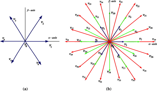
The power circuit diagram used for OEWIM is shown in Figure . It uses two isolated DC sources. In power circuit diagram, if x = y then it delivers two and three level output voltage. When x≠y, then it delivers four-level output voltage. If x = 2/3 and y = 1/3, then it generates “64” space vector combinations, out of these “37” space vector locations “36” vectors are called as active vectors and one null vector. Different switching combinations used to realize “37” voltage space vector locations are shown in Table .
Figure 1. Dual inverter fed OEWIM.
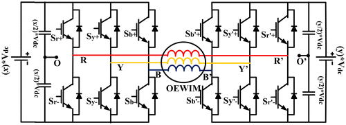
Table 1. Locations of voltage space vectors for OEWIM
The pole voltages (Vro, Vr′o′) per phase of OEWIM with respect to inverter-1 and 2 can be written as (1) and (2). In (1), “Sr” indicates switching pulse applied to R-phase of VSI-1, whereas in (2), “Sr′” indicated switching pulse of R′-phase of VSI-2.(1)
(1)
(2)
(2)
The difference of pole voltages per phase can be written as (3)(3)
(3)
Common mode voltage can be written from the difference of pole voltages and it is shown in (4)(4)
(4)
To write the phase voltages of OEWIM, it is assumed that the points OO′ are shorted and its expression is given by(5)
(5)
On simplification of (5) for phase voltage in terms of difference of pole voltages can be written as(6)
(6)
2.1. Discrete model of OEWIM
Detailed discrete model of OEIWM used for simulation and hardware implementation is shown in Figure . Vro, Vyo, Vbo, Vr′o′, Vy′o′ and Vb′o′ are the pole voltages of VSI-1 and VSI-2. ΔVrr′, ΔVyy′ and ΔVbb′ are difference of pole voltages. Vc is common-mode voltage. Vrr′, Vyy′ and Vbb′ are the phase voltages or input voltage to OEWIM.
Figure 2. Discrete model of OEWIM in stationary reference frames.
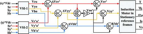
In (7)–(11) describe discrete model of OEWIM implemented in stationary reference frames. Stator and rotor voltage of OEWIM described by (7) and (8)(7)
(7)
(8)
(8)
Stator flux and rotor flux in terms of stator and rotor currents are given by (9) and (10)(9)
(9)
(10)
(10)
By considering ψs and is as state variables, the torque equation of OEWIM is given by(11)
(11)
In (7)–(11), Rs, Rr are stator and rotor resistance, “p” is derivative (d/dt), “P” number of poles. Ls, Lm and Lr are stator, rotor and mutual inductance respectively. Ψs(k), Ψr(k) are stator and rotor flux linkages at kth instant. is(k), ir(k) are stator and rotor currents. Vs(k) is stator is voltage vector and T(k) is electromagnetic torque at kth instant.
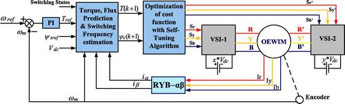
3. Proposed PTC of OEWIM with self tuning algorithm
The block diagram of Proposed PTC strategy with self tuning algorithm is shown in Figure . In the block diagram shown, VSI-1 and VSI-2 are used to feed OEWIM drive. If x = y = 1/2, then dual inverter delivers two-level voltage, it delivers four-level voltage when x≠y (x = 2/3 and y = 1/3). In four-level configuration it has 64 switching combinations distributed over 37 space vector locations.
Figure 3. Block diagram of proposed PTC of OEWIM with self-tuning algorithm.
Switching combinations used to obtain 37 space vector locations for four-level inversion is shown in Table . In Table “P” indicates upper switch in the respective leg of VSI is “ON”, whereas “N” indicates lower switch is “ON”. The switching combinations of inverters are “64”, out of these only 37 space vector locations are considered to reduce switching losses. The space vector locations used for two-level inversion (Praveen Kumar & Vinay Kumar, Citation2016) is described. The resultant voltage space vector is derived from (12) and (13). The output voltage of VSI-1 and VSI-2 is given by (12) and (13).(12)
(12)
(13)
(13)
The voltage space vector is given by (14)(14)
(14)
In (12)–(14), “Vs1” indicates voltage space phasor of VSI-1, “Vs2” indicates voltage space phasor of VSI-2, “Vo” represents resultant voltage space phasor. Figure (a) and (b) shows locations of active voltage space vectors. Vectors V1–V6 can deliver two-level output voltage, V7–V18 delivers three-level voltage and V19–V36 can give four-level output voltage.
Figure 4. Locations of voltage space vectors: (a) Two-Level Inversion and (b) Four-Level inversion.
In classical DTC, to operate OEWIM drive with four-level inversion it requires more than seven hysteresis controllers for its operation and it needs complex look-up table. These problems can be easily limited by using PTC algorithm, in this article PTC of OEWIM is implemented and in addition self-tuning algorithm. By adding self-tuning algorithm to classical PTC, the problems associated with manual selection of weighting factors can be eliminated. The proposed PTC algorithm can be implemented using five steps: (1) Measurement of variables at kth instant. (2) Estimating the variables (stator flux), this can’t be measurable. (3) Prediction of control variables. (4) Formulation of cost function and (5) Optimization of cost function.
3.1. Prediction model
The prediction model can be implemented by measuring the variables; the measured variables are used to estimate the variables which can’t be measurable. With the help of measured variables and estimated variables at kth instant the prediction model is implemented. The prediction model is implemented by considering OEWIM dynamics in discrete form. The discrete model of OEWIM is shown from (7)–(11).
By considering the control variables at kth instant, the prediction algorithm (k + 1 instant) used in this article is shown from (15)–(19).(15)
(15)
The prediction model was developed by considering stator flux and stator current as control variables. Well known forward Euler’s approach (16), is used to predict stator flux and stator current.(16)
(16)
The predicted stator flux was derived by using (16) and (15)(17)
(17)
The stator current (18) can be predicted by eliminating rotor flux and rotor current.(18)
(18)
From (17) and (18), the expression used to find predicted torque is given by (19)(19)
(19)
3.2. Formulation of cost function
The cost function is used to generate gating pulses required to turn “on” the VSI-1 and VSI-2, to realize respective voltage space vector for its operation. Optimization of cost function involves minimization of torque and flux ripples. The switching states, which can reduce both torque and flux ripples, are considered as switching states for VSI-1 and VSI-2. The cost function used in this article is same as classical PTC (Zhang & Yang, Citation2013) and it is given by (20). The cost function consists of two terms: the first term used to minimize torque error and the second term used to minimize flux error. The terms used in cost function are Tref which is generated from speed PI controller, T(k + 1) is predicted torque (19), ψsref is reference flux and ψs(k + 1) is predicted stator flux (17).(20)
(20)
In (20), ,
are torque and flux weighting factors. Cost function (20) contains two different quantities; in order to optimize cost function torque error and flux errors should multiplied by weighting factors.
3.3. Problem formulation and proposed self-tuned PTC
The cost function (20) optimized by proper selection of weighting factors. Improper selection of weighting factors may results distortions in phase-current, voltage, increased ripples in torque and flux, which may causes acoustic noise and vibration. To circumvent this problem weighting factors should be tuned properly. There is no specific method to find weighting factors, most of the control algorithms described (Cortés et al., Citation2009; Formentini et al., Citation2015; Zhou et al., Citation2015) will use empirical method for selection of weighting factors. The process of tuning and selection of weighting factors to reduce torque and ripples is cumbersome. In this article, an attempt is made to eliminate tuning of weighting factors. In this article, the procedure to select weighting factors is described.
The weighting factors used in classical PTC for OEWIM in two-level and four-level inversion modes are and
. The value of torque weighting factor used for simulation and experimentation are “1” and the flux weighting factor is obtained from several offline simulations, to find out an approximate value of
it is formulated as (21) and the value of “k” is determined empirically from branch and bound algorithm.
(21)
(21)
In (21), Tnom is rated torque of OEWIM, ψnom is rated flux of OEWIM and “k” is an integer. The value of “k” is selected empirically by performing several simulations; from simulations it is observed that the range of “k” is 1 to 5. Finally the value of “k” is taken as “3”, therefore the value of .
From various simulations and experimental verifications, it is observed that selection of weighting factors plays a vital role on performance of OEWIM drive. These problems can be easily addressed by self-tuning algorithm. This is the motivational factor to implement the proposed control algorithm. The procedure to implement self-tuning algorithm is clearly explained in Figure . The self-tuning algorithm is applied to find flux weighting factor. In order to find “” the flux error is optimised separately and it is initialized as g1. The value of g1 is set to a low value, if the value of g1 exist in a specified bound given by δ then it delivers
.
Figure 5. Flow chart of PTC to generate switching pulses with self tuning algorithm.
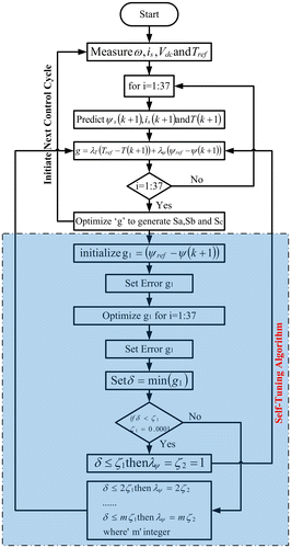
If this condition is violated then, δ varies as a multiple of specified iteration count “m”. For simulation and experimental verification the value of “m” is chosen to be 100. The value of varies for each iteration to optimize the flux error and the same value has been stored and applied into the cost function. The values of
varies continuously, to improve voltage and current profile and also reduce torque and flux ripples. This is called as self-tuning algorithm and the value of flux weighting factor is selected from online optimisation.
4. Simulation and hardware results
The block diagram of proposed PTC algorithm for OEWIM was shown in Figure was implemented with MATLAB/SIMULINK. The simulated algorithm was verified experimentally using dSPACE DS-1104 controller. The parameters of OEWIM used for simulation and experimentation are shown in Table . The simulation and experimental results are shown from Figures –. The OEWIM is operated with two-level and four-level inversion for various speeds. On interest of brevity, the results are shown only for three speeds of operation. The DC-link voltage used for VSI-1 and VSI-2 are 270 and 270 V then dual inverter configuration delivers two-level output voltage, four-level inversion was obtained by operating VSI-1 and VSI-2 with voltages 360 and 180 V respectively. The total DC link voltage used for both configurations is 540 V.
Table 2. Parameters of OEWIM used for simulation and experiment
Figure 6. Simulation results of OEWIM in forward motoring for speeds of 50, 100 and 125 rad/s: (a) Two-level PTC, (b) Proposed two-level PTC, (c) Four-level PTC and (d) Proposed Four-level PTC.
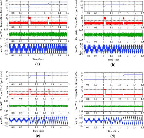
Figure 7. Simulation results of OEWIM in reverse motoring for 50, 100 and 125 rad/s: (a) two-level PTC, (b) proposed two-level PTC, (c) four-level PTC and (d) Proposed four-level PTC.
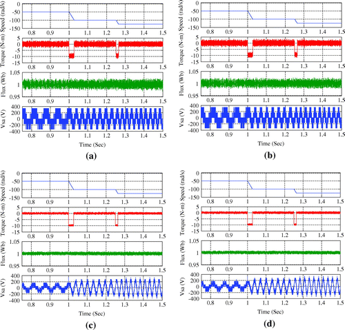
Figure 8. Simulation results of OEWIM in forward and reverse motoring: (a) two-level PTC, (b) proposed two-level PTC, (c) four-level PTC, (d) proposed four-level PTC, (e) variation of flux weighting factor for 50, 100 and 125 rad/s and (f) variation of flux weighting factor for 50, 100 and 125 rad/s.
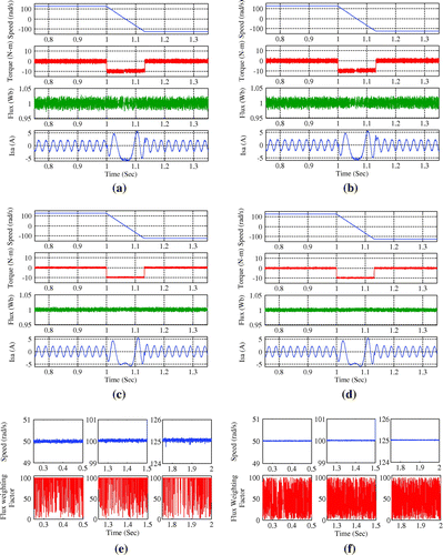
Figure 9. Experimental results of OEWIM in forward motoring for speed variations of 50, 100 and 125 rad/s: (a) Two-level PTC (b) Proposed two-level PTC (c) Four-level PTC and (d) Proposed four-level PTC.
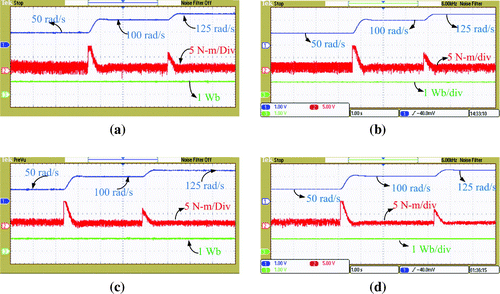
Figure 10. Experimental results of OEWIM for speed variation from forward motoring (100 rad/s) to reverse motoring (−100 rad/s): (a) Two-level PTC (b) Proposed two-level PTC (c) Four-level PTC and (d) Proposed four-level PTC.
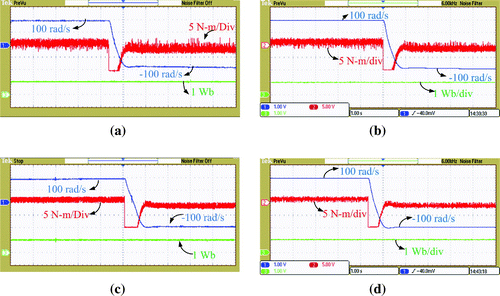
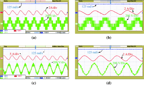
Figure 11. Steady state currents of OEWIM at 125 rad/s: (a) Two-level PTC (b) Proposed two-level PTC (c) Four-level PTC and (d) Proposed four-level PTC.
4.1. Simulation results
The proposed PTC algorithm was simulated with MATLAB. The simulation results are shown for various speeds of operation. The simulation results of OEWIM were shown for 50, 100 and 125 rad/s in forward and reverse motoring. The sampling time used for simulation and experimentation is 100 μs. Figure shows simulation results of OEWIM in forward motoring for classical PTC and proposed self-tuned PTC algorithms.
Figure demonstrates torque, flux and phase voltage of OEWIM in forward motoring for step change in speed. Figure (a) and (b) shows classical PTC and proposed PTC algorithms for OEWIM in forward motoring for two-level inversion. Figure (c) and (d) shows classical and proposed PTC algorithms of OEWIM for four-level inversion. From Figure it is observed that proposed PTC algorithms give same characteristics as classical PTC, when compared to classical PTC proposed self-tuning PTC gives less ripple in torque and flux. Figure demonstrates torque, flux and phase voltage of OEWIM for step change of speed in reverse motoring. Figure (a) and (b) shows simulation results of classical PTC and proposed PTC algorithms for OEWIM in forward motoring for two-level inversion, whereas Figure (c) and (d) shows simulation results of classical and proposed PTC algorithms of OEWIM for four-level inversion. Figure demonstrates torque, flux and stator phase currents for OEWIM for step changes in speed variation from forward motoring (125 rad/s) to reverse motoring (−125 rad/s). Figure (a) and (b) shows simulation results for classical and proposed PTC for two-level inversion, whereas Figure (c) and (d) shows simulation results for classical and proposed PTC for two-level inversion Figure (e) and (f) gives variation of flux weighting factor for proposed self-tuned PTC for speeds of 50, 100 and 125 rad/s. From 8(e) and (f) it is clear that weighting factor of flux is not constant, it will vary continuously to optimise cost function and speed ripple is less in four-level PTC on comparison to two-level PTC. The proposed algorithm uses an adjustable weighting factor rather than fixed weighting factors used in classical PTC. As the weighting factor is fixed in classical PTC it influences the performance of OEWIM drive and in proposes self-tuned PTC the weighting factor is adjusted to minimise the torque and flux ripples, hence it maintains lesser torque and flux ripples. The proposed algorithm was tested by applying sudden change in speed to operate OEWIM in acceleration or deceleration mode. During the sudden change in speed OEIWM maintains constant flux and the accelerated or decelerated speeds are obtained by proper selection of voltage vectors.
4.2. Experimental results
The proposed algorithm was implemented with dSPACE-1104, to verify its effectiveness. The experimental results are shown for forward motoring, reverse motoring. Figures – shows experimental results of OEWIM for speeds of 50, 100 and 125 rad/s.
Figure shows experimental response of OEWIM for forward motoring and it exhibits speed, torque and flux characteristics for 50, 100 and 125 rad/s. Figure (a) and (b) shows forward motoring for classical two-level PTC and proposed PTC respectively. Figure (c) and (d) represents forward motoring of OEWIM for four-level PTC and Proposed four-level PTC respectively.
Figure demonstrates forward and reverse motoring of OEWIM at 100 rad/s. Figure (a) and (b) demonstrates speed, torque and flux characteristics of OEWIM for two-level PTC and proposed PTC. Figure (c) and (d) represents speed, torque and flux characteristics of OEWIM for four-level PTC and proposed self-tuned PTC.
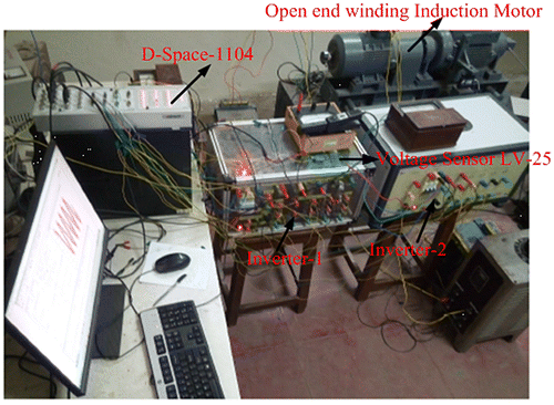
From Figures and , it is observed that the proposed self tuned PTC can give same characteristics as that of classical PTC. From Figures and it is also observed that torque and flux ripples of proposed self-tuned PTC are less when compared to classical PTC. Figure shows speed, phase current and phase voltage of OEWIM at a steady-speed of 125 rad/s. Figure (a) and (b) represents phase current and voltage of OEWIM for two-level PTC and proposed PTC, whereas Figure (c) and (d) represents phase current and voltage for four-level PTC and proposed self-tuned PTC. Figure is test bench used for experimentation. Figure contains OEWIM, two two-level voltage source inverters, current transducers, voltage transducers and personnel computer with MATLAB synchronised to dSPACE-1104 controller board.
Figure 12. Experimental set-up used to test proposed self-tuned PTC algorithms.
The simulation and experimental results of OEWIM configuration with classical PTC and proposed PTC algorithms for two-level configuration and proposed self-tuned PTC algorithms were shown from Figures –. The simulation and experimental results shows the proposed algorithm can be implementable for multi-level inversion scheme.
The overall execution time required for classical PTC and Proposed PTC algorithms were nearly same. The execution time of classical PTC strategy is 60 μs and the proposed PTC strategy is 65 μs. Table shows steady-state torque and flux ripple of OEWIM drive with classical and proposed PTC algorithms for two-level and proposed four-level inversion schemes. From simulation and experimental results, it is evident that the proposed PTC algorithm features all benefits of classical PTC.
Table 3. Steady-state torque and flux ripples of proposed and classical PTC
5. Conclusion
In this article, self-tuned predictive torque of OEWIM for two-level and four-level inversion schemes were implemented to reduce torque and flux ripples. This study introduces a novel PTC of OEWIM with self-tuning approach to select the weighting factors using online optimisation. Self-tuning of weighting factors eliminate the process of manual selection and time consuming online and offline simulations. This article describes the implementation of PTC algorithms for OEWIM with multi-level inversion. The simulated and experimental results are presented to verify the effectiveness of the proposed algorithm for two-level and multi-level configuration. Proposed self-tuned PTC algorithm can be implementable for multi-variable cost function optimization. The objectives in this study are: (i) discrete implementation dual inverter fed OEWIM (ii) implementation of PTC algorithm for OEWIM (iii) introduces a novel self tuned PTC strategy (iv) enhanced weighting factor selection (v) obtains features of classical PTC without increasing the computational burden. The future scope of this article is to extend the proposed algorithm towards switching frequency reduction and common-mode voltage suppression. In this article, only torque and flux errors are optimised in cost function.
Funding
The authors received no direct funding for this research.
| Abbreviations | ||
| PTC | = | Predictive Torque Control |
| DTC | = | Direct Torque Control |
| OEWIM | = | Open-End Winding Induction Motor |
| FOC | = | Field Oriented Control |
| MPDTC | = | Model Predictive Direct Torque Control |
| FCS-PTC | = | Finite Control Set PTC |
| VSI | = | Voltage Source Inverter |
| DC | = | Direct Current |
| SVM | = | Space Vector Modulation |
Additional information
Notes on contributors
Kunisetti V. Praveen Kumar
Kunisetti V. Praveen Kumar received his BTech degree in Electrical and Electronics Engineering from JNTU, Kakinada, India, in 2011 and MTech, degree from JNTU, Kakinada, India, in 2014. Presently he is doing research in the area of Power Electronics and Drives at National Institute of Technology, Warangal, India.
K.M. Ravi Eswar
K.M. Ravi Eswar received his BTech degree in Electrical and Electronics Engineering from JNTU, Ananthapur, India, in 2014 and MTech, degree from VIT University, Vellore, India, in 2016. Presently he is doing research in the area of Power Electronics and Drives at NIT, Warangal, India.
Thippiripati Vinay Kumar
Thippiripati Vinay Kumar received his BTech degree in Electrical and Electronics Engineering from JNTU, Hyderabad, India, in 2005 and MTech, degree from JNTU, Hyderabad, India, in 2008. He received his PhD degree from National Institute of Technology, Warangal, India, in 2015. Since 2013, he is working as an Assistant professor in National Institute of Technology, Warangal, India. His research interests are power electronics and drives, multi level inverters and renewable energy.
References
- Abdelli, R., Rekioua, D., & Rekioua, T. (2011). Performances improvements and torque ripple minimization for VSI fed induction machine with direct control torque. ISA Transactions, 50(2), 213–219.10.1016/j.isatra.2010.11.008
- Arbind Kumar, B., Fernandes, G., & Chatterjee, K. (2004). Direct torque control of open-end winding induction motor drive using the concept of imaginary switching times for marine propulsion systems. In Conference Proceedings: IEEE PESC-04 (Vol. 2, pp. 1214–1219).
- Beerten, J., Verveckken, J., & Driesen, J. (2010). Predictive direct torque control for flux and torque ripple reduction. IEEE Transactions on Industrial Electronics, 57(1), 404–412.10.1109/TIE.2009.2033487
- Correa, P., Pacas, M., & Rodriguez, J. (2007). Predictive torque control for inverter-fed induction machines. IEEE Transactions on Industrial Electronics, 54(2), 1073–1079.10.1109/TIE.2007.892628
- Cortés, P., Kouro, S., Rocca, B., Vargas, R., Rodríguez, J., León, J. I., Vazquez, S., & Franquelo, L. G. (2009). Guidelines for weighting factors design in model predictive control of power converters and drives. In IEEE International Conference on Industrial Technology (pp. 1–7).
- Davari, S. A., Khaburi, D. A., & Kennel, R. (2012, March). An improved FCS–MPC algorithm for an induction motor with an imposed optimized weighting factor. IEEE Transactions on Power Electronics, 27(3), 1540–1551.10.1109/TPEL.2011.2162343
- Formentini, A., Trentin, A., Marchesoni, M., Zanchetta, P., & Wheeler, P. (2015). Speed finite control set model predictive control of a PMSM fed by matrix converter. IEEE Transactions on Industrial Electronics, 62(11), 6786–6796.10.1109/TIE.2015.2442526
- Geyer, T., Papafotiou, G., & Morari, M. (2009, June). Model predictive direct torque control—Part I: Concept, algorithm and analysis. IEEE Transactions on Industrial Electronics, 56(6), 1894–1905.10.1109/TIE.2008.2007030
- Habetler, T. G., Profumo, F., Pastorelli, M., Tolbert, L. M. (1992). Direct torque control of induction machines using space vector modulation. IEEE Trans Ind Appl., 28(5), 428–436.
- Jun-Koo Kang, J., & Seung-Ki Sul, S. (1999). New direct torque control of induction motor for minimum torque ripple and constant switching frequency. IEEE Transactions on Industry Applications, 35(5), 1076–1082.10.1109/28.793368
- Karamanakos, P., Stolze, P., Kennel, R. M.¸ Manias, S., & du Toit Mouton, H. (2014, June). Variable switching point predictive torque control of induction machines. IEEE Journal of Emerging and Selected Topics in Power Electronics, 2(2), 285–295.10.1109/JESTPE.2013.2296794
- Miranda, H., Cortes, P., Yuz, J. I., & Rodriguez, J. (2009). Predictive torque control of induction machines based on state-space models. IEEE Transactions on Industrial Electronics, 56(6), 1916–1924.10.1109/TIE.2009.2014904
- Mukherjee, S., & Poddar, G. (2010). Direct torque control of squirrel cage induction motor for optimum current ripple using three level inverter. IET Power Electronics, 3(6), 904–914.10.1049/iet-pel.2009.0177
- Nemec, M., Nedeljkovic, D., & Ambrozic, V. (2007). Predictive torque control of induction machines using immediate flux control. IEEE Transactions on Industrial Electronics, 54(4), 2009–2017.10.1109/TIE.2007.895133
- Papafotiou, G., Kley, J., Papadopoulos, K. G., Bohren, P., & Morari, M. (2009 June). Model predictive direct torque control—Part II: Implementation and experimental evaluation. IEEE Transactions on Industrial Electronics, 56(6), 1906–1915.10.1109/TIE.2008.2007032
- Praveen Kumar, K. V., & Vinay Kumar, T. (2016). Experimental implementation of direct torque control of open-end winding induction motor. In Conference Proceedings: IEEE TENCON-2016 (pp. 3318–3323.
- Praveen Kumar, K. V., & Vinay kumar, T. (in press). Predictive torque control of open-end winding induction motor drive fed with multi-level inversion using two two-level inverters. IET Digitial Lirary, IET Electric Power Applications. doi:10.1049/iet-epa.2017.0209
- Rodriguez, J., & Cortes, P. (2012). Predictive control of power converters and electrical drives. Hoboken, NJ: John Wiley & Sons Ltd.10.1002/9781119941446
- Rodriguez, J., Pontt, J., Silva, C., Cortes, P., Ammanna, U., & Rees, S. (2004, September). Predictive direct torque control of an induction machine. In Conference Proceedings: EPE-PEMC 2004 (Power Electronics and Motion control Conference). Lativa: Riga.
- Rojas, C. A., Rodriguez, J., Villarroel, F., Espinoza, J. R., Silva, C. A., & Trincado, M. (2013). Predictive torque and flux control without weighting factors. IEEE Transactions on Industrial Electronics, 60(2), 681–690.10.1109/TIE.2012.2206344
- Suresh, L., Nagarjun, S., & Somasekhar, V. T. (2017, April). Improvised SVPWM strategies for an enhanced performance for a four-level open-end winding induction motor drive. IEEE Transactions on Industrial Electronics, 64(4), 2750–2759.
- Takahashi, I., & Noguchi, T. (1986). A new quick-response and high-efficiency control strategy of an induction motor. IEEE Transactions on Industry Applications, 22(5), 820–827.10.1109/TIA.1986.4504799
- Vinay, K. T., & Srinivasa, R. S. (2014). Hardware implementation of direct load angle controlled induction motor drive. Electric Power Components and Systems, 42(14), 1505–1516.
- Vishnu Prasad, M., Anil Kumar, B., & Srinivasa Rao, S. (2016, July). Enhanced weighting factor selection for predictive torque control of induction motor drive based on VIKOR method. IET Electric Power Applications, 10(9), 877–888.
- Vishnu Prasad, M., Anil Kumar, B., & Srinivasa Rao, S. (2017, May). Finite control set predictive torque control for induction motor drive with simplified weighting factor selection using TOPSIS method. IET Electric Power Applications, 11(5), 749–760.
- Zhang, Y., & Yang, H. (2013). Torque ripple reduction of model predictive torque control of induction motor drives. In Proceedings of EEE Energy Conversion Congress and Exposition (pp. 1176–1183).
- Zhang, Y., & Yang, H. (2014). Model predictive torque control of induction motor drives with optimal duty cycle control. IEEE Transactions on Power Electronics, 29(12), 6593–6603.10.1109/TPEL.2014.2302838
- Zhang, Y., & Yang, H. (2015, July). Generalized two-vector-based model-predictive torque control of induction motor drives. IEEE Transactions on Power Electronics, 30(7), 3818–3829.10.1109/TPEL.2014.2349508
- Zhou, D., Zhao, J., & Liu, Y. (2015). Predictive torque control scheme for three-phase four-switch inverter-fed induction motor drives with Dc-link voltages offset suppression. IEEE Transactions on Power Electronics, 30(6), 3309–3318.10.1109/TPEL.2014.2338395