 ?Mathematical formulae have been encoded as MathML and are displayed in this HTML version using MathJax in order to improve their display. Uncheck the box to turn MathJax off. This feature requires Javascript. Click on a formula to zoom.
Abstract
In recent years the electric energy sector has been experiencing an extension into distributed generation, and in this context microgrids have been achieving increasing importance. Microgrids are composed of renewable and conventional generation systems, storage and distributed loads that working under a system control that could be operated in grid connected or islanded mode. However, the increasing number of renewable energy sources and distributed generators requires new strategies for the operation and management of the electricity grid in order to improve the power-supply reliability and power quality (PQ). However, power quality compensation i.e. voltage sag, swell, harmonics reduction in current and voltage waveform are the real problem in power flow between microgrid and loads. Unified power quality conditioner (UPQC) is a device which can mitigate all PQ related problem in both utility and microgrid system. In the proposed system PV/Wind/Fuel cell/Battery are connected to a common bus where different loads are connected and UPQC is integrated with the microgrid and grid to compensate PQ related problem. The simulation model of series active filter, shunt active filter, UPQC and microgrid system are design in MATLAB software and results are verified by using First Fourier Transform analysis. The study concludes with a comparison between the microgrid side disturbances and grid side disturbances, and it is observed that the harmonics in source current is reduce below 5% in all cases and also compensate the voltage sag and swell.
Public Interest Statement
The present energy development is the hybrid system projection in which renewable sources and storage systems provide a high percentage of energy needs, leaving the use of conventional system for emergency cases. Hence, microgrids represent a workable solution for the electricity demands in isolated or non-electrified areas. However, power quality compensation i.e voltage sag, swell, harmonics reduction in current and voltage waveform are the real problem in power flow between microgrid and loads. This paper represents the integration of solar photo voltaic, fuel cell and wind energy system based microgrid system along with power quality analysis by using unified power quality conditioner (UPQC). The said model is simulated in Matlab Simulation and results are verified by using First Fourier Transform analysis. The microgrid is basically used in non-electrified and isolated areas where electricity demand is very much essential and the power quality problem is minimized by integrating UPQC with microgrid.
1. Introduction
Electric power system is getting polluted due to an increase in power electronics-based converters in household appliances and industrial equipment. Significantly increase in nonlinear loads, such as power converters, switch-mode power supplies, arc furnaces, variable speed drives, computers, fax machines, and household electronic equipment installed at the distribution level plays a key role in distorting the sinusoidal waveform of supply voltages and currents. The main concern of electricity consumers is to obtain uninterruptable power supply with improved power quality (Singh, Chandra, & Al-Haddad, Citation2015). Thus, to ensure quality power to all consumers even when some of the loads are themselves polluting in nature, becomes a major challenge. The power quality problems related to currents are mainly harmonics, insufficient reactive power, and unbalanced loads, and these affect the performance of other equipment, which are coupled at point of common connection (PCC). International standards have been recommended to specify the permissible limit of power quality problems and to provide guidelines for the end user, manufacturer, and utility to improve the quality of power (Ghosh & Ledwich, Citation2009; Singh, Al-Haddad, & Chandra, Citation1999).
Distributed energy resources (DERs) such as solar, fuel cell and wind power are gaining growing awareness due to their economic, environmental, and technologic incentives. Microgrid is a key technology for integration of DERs, energy storages (ESs), and different loads (Hatziargyriou, Asano, Iravani, & Marnay, Citation2007; Olivares et al., Citation2014). However, microgrid is nothing but the combination of number of DERs, ESs with different power electronics converters are operated in grid connected or islanded mode (Benachaiba, Haidar, Habab, & Abdelkhalek, Citation2011). In a grid connected Microgrid system the Power Quality (PQ) problem is mainly divided into two categories i.e. PQ problem in utility side and customer side. However, voltage sag, swell, interruption & flickering are mainly related to utility side where as harmonics distortion, reactive power demand and lagging power factor are mainly related to customer PQ problem (Ahmadi & Ferdowsi, Citation2014; Singh et al., Citation1999). Among all these problem main disturbance in utility side is the voltage interruption and voltage drop where as customer side is the harmonics distortion. Now a day UPQC is the popular choice in achieving good power quality level, utilized for harmonics suppression, reactive power generation/absorption, and providing compensating currents to balance the load. However, UPQC is a device which is connected at the point of common coupling and mitigates the PQ related problems in between utility/microgrid and load (Kesler & Ozdemir, Citation2011). The main function of UPQC is to control the power flow and reduce the harmonics distortion both in voltage and current waveform. The theory, modeling and application of a unified power quality conditioner have been described by Chen et al. (Citation2000). Basu, Das, and Dubey (Citation2007) have made a comparative evaluation of two models of UPQC for suitable interface to enhance power quality. Montero, Cadaval, and Gonzalez (Citation2007) have compared different control strategies for shunt active power filters in three-phase four-wire systems. Lee, Lee, and Seok (Citation2004) described the control techniques of series active power filters compensating for source voltage unbalance and current harmonics. An efficient voltage sag detection technique for a dynamic voltage restorer has been developed by Fitzer, Barnes, and Green (Citation2002). The design, simulation and experimental investigations on a shunt active power filter for harmonics and reactive power compensation was described by Jain, Agarwal, and Gupta (Citation2003).
Applications with photovoltaic (PV) energy and wind energy have been increased significantly due to the rapid growth of power electronics techniques. Generally, PV power and wind power are complementary since sunny days are usually calm and strong winds are often occurred at cloudy days or at nighttime. Hence, the hybrid PV/wind system has higher reliability to deliver continuous power than either individual source. Traditionally, a substantial energy storage battery bank is used to deliver the reliable power and to draw the maximum power from the PV arrays or the wind turbine for either one of them has an intermittent nature. However, the purpose of fuel cell is to transform the chemical energy of fuel to electric energy. A fuel cell is environmental friendly, noise free, high efficiency as compare to other sources as and it can be interfaced with AC and DC distribution system using different power electronics devices described by Noroozian, Abedi, Gharehpetian, and Bayat (Citation2010). The design of 48 V fuel cell with inverter application and ultra capacitor for energy storing purposes explain by Nergaard, Ferrell, Leslie, and Lai (Citation2002). Bucci, Ciancetta, Fiorucci, and Vegliò (Citation2007) has described the various types of fuel cell technology with Matlab modeling and implementation of Proton Exchange Membrane (PEM) fuel cell.
This work presents the operation of UPQC connected to both utility grid and microgrid with linear and nonlinear loads. With the developed model in Matlab/Simulink it will be evaluated the performance and control of a hybrid filtering system, in relation to compensation of current and voltage harmonic distortion in PCC of the microgrid and utility grid. The result shows that UPQC can compensate voltage sag, swell and load current and voltage harmonics both in utility grid and microgrid side.
This paper is organized as follows. The proposed microgrid is introduced in Section 2. In Section 3, the design solar PV is explain. Design of wind energy system is explain in Section 4. Section 5, describe the design of fuel cell system. The control methods of UPQC are explained in Section 6. The result analysis and conclusions are drawn in Section 7.
2. Proposed system
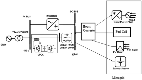
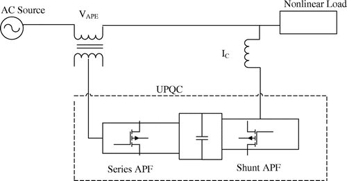
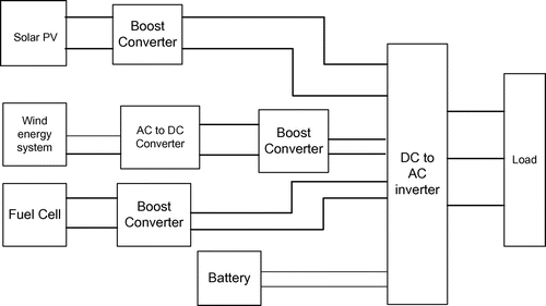
The general diagram for microgrid/grid system with UPQC was shown in Figure . The diagram shows here is the combination microgrid and grid connected to different load with UPQC, where the microgrid is design with solar PV/wind energy /Fuel cell and battery system which is connected to a common DC bus through a switch. From the DC bus the power is converted to AC with the help of power inverter and the UPQC is placed in between the microgrid/grid and non linear load.
The purposed system mainly consist
| • | Microgrid (Solar PV, Fuel cell, Wind and Battery) | ||||
| • | Utility Grid (Source) | ||||
| • | Power Inverter/ Converter | ||||
| • | UPQC | ||||
2.1. Microgrid
The microgrid is nothing but the integration of number of renewable energy sources, stroge system, and different power electronics converters for control the power flow between grid and load. Here the energy sources are solar PV/Fuel cell/Wind and battery. PV/Fuel/Wind and battery power is converted to DC power by using maximum power point tracking (MPPT) and boost converter and is again converted to AC by using inverter.
2.2. Utility grid
The utility grid is the distribution side energy source. The microgrid and UPQC is connected to the utility grid through a common bus. The linear and nonlinear loads are connected to PCC through UPQC.
2.3. Power inverter/converter
The purpose of DC to DC converter is required for PV system for proper voltage level at DC bus. It consists of MPPT with boost converter which will provide proper voltage and power at the output. In order to integrate the microgrid with the utility grid a power inverter is inserted in between these two.
2.4. UPQC device
A UPQC consist of two inverter connected to a common dc-link capacitor. The series inverter is connected though a series transformer and the shunt inverter is connected in parallel with the point of common coupling. The series inverter acts as a voltage source where as the shunt one is acts as a current source. The main function of UPQC is to control the power flow and reduce the harmonics distortion both in voltage and current waveform.
3. Design of microgrid
3.1. Modeling of solar PV
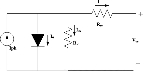
Solar photo-voltaic system works on the principle that when a light energy falls on solar cell it converts it to electrical energy. The equivalent model of solar PV system representing single diode model is shown in Figure . It consist of a photo current Iph which depends on temperature and irradiation, the series resistance represent the internal resistance due to which current I flows and the shunt resistance describe the flow of Ish which is a leakage current (Altas & Sharaf, Citation2007).
The load current, photo current and other equation are given below from Equations (1) to (5)(1)
(1)
(2)
(2)
(3)
(3)
(4)
(4)
(5)
(5)
where IPV is the diode photo current in (A), I0 is the reverse saturation current of diode in (A), Ish is the leakage current in (A), Vpv is the diode voltage in (V), Voc is the open circuit voltage in (V), Rse is the series resistance in (Ω), Rsh is the shunt resistance in (Ω), Isc is the short circuit current in (A), q is the electron charge, k is Boltzmann constant, A is the diode ideality factor, T is the temperature of the p-n junction in (Kelvin), NP is No. of cells connected in parallel and Ns is No. of cells connected in series.
3.2. Maximum power point tracking (MPPT)
The solar panel efficiency is increased by the use MPP technique. The MPPT is the application of maximum power transfer theorem which says that the load will receive maximum power when the source impedance is equal to load impedance. The MPPT is a device that extracts maximum power from the solar cell and changes the duty ratio of DC/DC converter in order to match the load impedance to the source.
3.3. Perturb & observe (P&O) MPPT algorithm
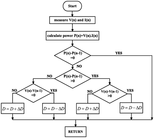
There are many method of MPPT out of which Perturb & Observe (P&O) technique is mostly used by the researcher due to its simplicity and cost effective. This method works on an algorithm that first PV panel terminal voltage and current are measured and corresponding value of power is measured denoted by P (n − 1). The detail algorithm is shown in below flow chart Figure which describes the algorithm for designing the MPP system using P&O by Matlab simulation (Femia, Petrone, Spagnuolo, & Vitelli, Citation2005).
In this algorithm, the module voltage is periodically given a perturbation and the corresponding output power P (n) is compared with the previous perturbing cycle P (n − 1). In this algorithm a slight perturbation is introduce to the system. If the power increases i.e. P (n) − P (n − 1) > 0 due to the perturbation then the perturbation is continued in the same direction and the duty cycle of the boost converter will increase or decrease depending upon PV panel voltage i.e. D + ΔD for V (n) − V (n − 1) > 0 and D − ΔD for the case V (n) − V (n − 1) ˂ 0. After the peak power is reached the power at the MPP is zero i.e. at P (n) − P (n − 1) = 0 and next instant power decreases and hence after that the perturbation is reverses.
Where V (n) is the PV panel terminal voltage in (V), V (n − 1) is voltage due to perturbation in (V), I (n) is the PV panel current in (A), P (n) is the PV panel power in (W), P (n − 1) is the power due to perturbation in (W), D is the duty cycle of boost converter, where ΔD is the change in duty cycle.
3.5. DC/DC boost converter
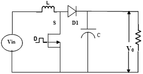
A boost converter is a step up DC/DC converter which increases the solar voltage to desired output voltage as required by load. The configuration is shown in Figure , which consists of a DC input voltage Vin, inductor L, switch S, diode D1, capacitor C for filter, and load resistance R.
When the switch S is ON the boost inductor stores the energy fed from the input voltage source and during this time the load current is maintain by the charged capacitor so that the load current should be continuous. When the switch S is OFF the input voltage and the stored inductor voltage will appear across the load hence the load voltage is increased. Hence, the load voltage is depends upon weather switch S in ON or OFF and this is depends upon the duty ratio D.
If the switch operates with a duty ratio D, then the output DC voltage is given by Equation (6).(6)
(6)
The minimum and maximum duty ratio, Dmin and Dmax for a lossless boost converter is given by the following equations:(7)
(7)
where Dmax is the maximum duty ratio required to keep the converter in continuous conduction mode (CCM).(8)
(8)
where Dmin is the minimum duty cycle required to keep the converter in CCM.
3.6. Matlab/simulation of PV system
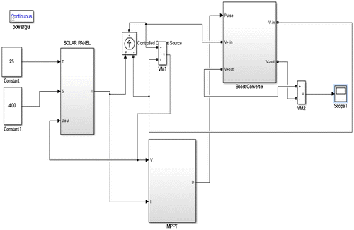
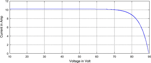
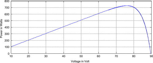
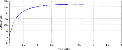
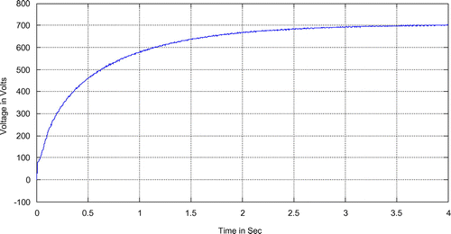
In general the efficiency of a PV unit is extremely low, therefore it is essential to operate the PV unit at its peak point so that the highest power can be provided to the load at any condition. A step up converter which is located next to the PV unit extracts maximum power with the help of P&O MPPT method which matching the impedance of the circuit to the impedance of the PV unit Impedance matching is possible by changing the duty ratio of the boost converter. The simulation of solar PV with P&O MPPT and Boost converter is shown in Figure . The I–V and P–V characteristic of PV unit is shown in Figures and and the boost converter output voltage is shown in Figure .
4. Wind energy system
The diagram shown in Figure is the basic wind energy conversion system model. The wind kinetic energy first converted to rotational motion and by the use of gear box it is matches the speed of turbine and generator. The function of generator is to convert the mechanical energy of turbine to electrical energy. A rectifier is used to convert the AC voltage to DC and a battery is connected in such a way that it can charged both the way i.e. a bidirectional converter is used to charged the battery (Tafticht, Agbossou, Cheriti, & Doumbia, Citation2006).
4.1. Modeling of wind turbines
The kinetic energy of wind is converted to rotational motion i.e. wind power to mechanical power conversion is done with the help of wind turbine blade in contact with wind speed. So different equation are given below for power generation from wind is from Equations (9)–(11).(9)
(9)
where PM is the mechanical power, ρ is the air density, β is the pitch angle, R is the blade radius-speed of the wind, λ is the tip-speed ratio, given by λ = ΩR/V.
where Ω is rotor speed of rotation (in rad/sec) and CP can be expressed as the function of the tip-speed ratio (λ)(10)
(10)
(11)
(11)
where CP is power coefficient of turbine and λ1 is any constant.
4.2. Generator
The kinetic energy of the turbine is converted to mechanical energy and the turbine shaft is connected to rotor shaft of the generator. The power is transmitted from turbine to generator with the help of shaft. The generator rotor winding is known as armature which is rotates in between the magnetic stationary field and produce electrical voltage according to general generator principle.
4.3. Permanent magnet synchronous generator (PMSG)
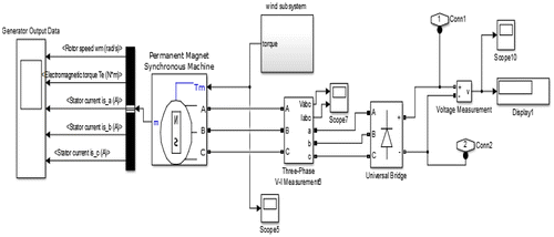
In case of Permanent Magnet Synchronous Generator (PMSG) the magnetic field is stationary and the flux is produce by permanent magnet not by electromagnet, so a separate supply is not required for creation of magnetic field and the field flux remain constant. Another advantage of PMSG is that there is no requirement of slip ring (Jamil, Gupta, & Singh, Citation2012; Koutroulis & Kalaitzakis, Citation2006). All other construction remains same as that of normal synchronous generator. The simulation of wind system with PMSG and rectifier is shown in Figure which gives the DC output voltage as required by the microgrid.
The e.m.f induced in a synchronous generator is given by Equation (12).(12)
(12)
where, f is te frequency in (Hz), is maximum flux in (Wb) and t is number of turns.
5. PEM fuel cell model
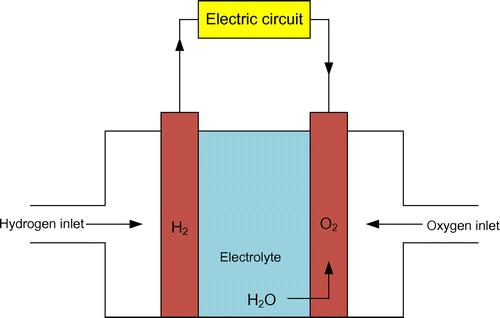
The fuel cell system considered in this paper is consisting of a fuel cell reformer and stack which generates electricity due to electrochemical reaction of hydrogen and oxygen as shown in Figure . The fuel cell is a device which produces electricity from the chemical reaction of hydrogen and oxygen. The reformer is presented by a first order equation and the corresponding transfer function is shown in Equation (13), the stack is also represented by a first order time delay equation with transfer function is shown in Equation (14).(13)
(13)
(14)
(14)
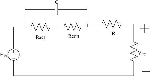
The mathematical model for design of PEM fuel cell by different set of equation is shown below form Equations (15)–(22) and the simplified PEM model is shown in Figure .(15)
(15)
(16)
(16)
(17)
(17)
(18)
(18)
(19)
(19)
(20)
(20)
(21)
(21)
(22)
(22)
where EN is the open circuit thermodynamic potential of the cell in (V), each cell model coefficients of parametric are representing by ξ1, ξ2, ξ3, ξ4 and ψ, the ohmic voltage drop is represented by Vohmic in (V), RM is proton conduction equivalent membrane resistance in (Ω), RC is the electron conduction equivalent contact resistance in (Ω), Vcon is the concentration over potential in (V), K is No. of cells connected in series, A is membrane area in (cm2), RC is contact resistance in (ohm), C is capacitance in (Farad), ξ’s is model coefficients, Ψ is empirical parameter, Jmax is maximum current density in (A/cm2), pressure of hydrogen PH2 in (atm), pressure of oxygen PO2 in (atm) and temperature T in (Kelvin).
5.1. Matlab simulation of fuel cell with boost converter
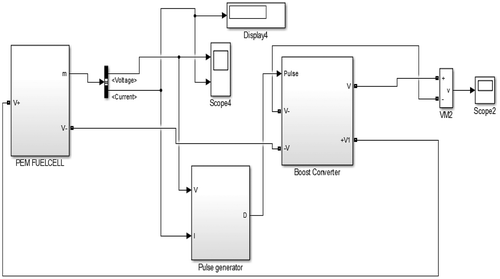
A simple fuel cell typically produces output voltage in the range of 0.5–0.9 V. Since this low voltage becomes insufficient for real-time applications, a stack of fuel cells are arranged in series and a step up converter is connected to so that the required voltage can be attained. The simulation diagram of Fuel cell with boost converter is shown in Figure and output voltage of boost converter is shown in Figure .
6. Control strategies of the UPQC System
There are several control strategies available to find out the reference values of the voltage and the current of UPQC. The Figure shows the block diagram for control strategies of UPQC system. The concept of instantaneous active power (p) and reactive power (q) and its application in shunt filter reference current generation, the synchronous reference frame theory, the fuzzy logic control (FLC) for the control of UPQC method are some of the above mentioned control strategies (Suresh, Patnaik, Suresh & Panda, Citation2011). Based on the above discussion, d-q theory with hysteresis current control mode is suitable for parallel mode operation of UPQC system and d-q theory with PWM voltage control mode is suitable for interruption mode operation. The hysteresis control method is simple to implement and it has enhanced system stability, increased reliability and mitigates power quality problems.
UPQC consists of two main controllers as follows:
| • | Series Active Power Filter | ||||
| • | Shunt Active Power Filter | ||||
6.1. Series active power filter
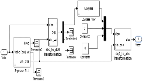
The case of series APF Park’s transformation method is used for generation of unit vector signal. The actual voltage and the reference are converted to dq0 from abc coordinates and both are compared in dq0 reference frame. After the comparison both are again converted to abc reference frame. From PLL (phase locked loop) Ø can be generated which is required for Park’s transformation and inverse Park’s transformation. The switching pulses required for VSI conduction are generated from the comparison of selected output voltage (Vc*) with the sensed series APF output voltage (Vc) in a hysteresis voltage controller. The simulation diagram for control scheme of Series APF is shown in Figure .
The Park’s transformation and inverse Park’s transformation are given below
6.2. Shunt active power filter
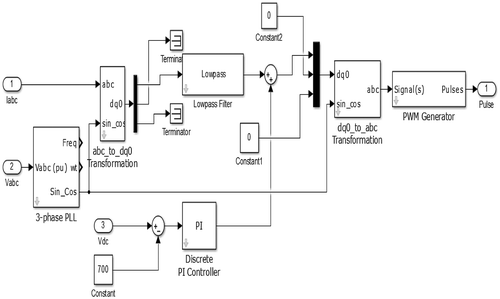
The shunt APF is usually joined in parallel to the system which indicates the harmonics content. To eliminate the harmonics, the equal amount of harmonic compensating current is injected in opposite phase w.r.t the harmonic current. The Matlab simulation of control scheme of shunt active filter is shown in Figure where the transfer of source current from a-b-c to d-q frame is achieve by 3-phase PLL circuit. In nonlinear load the source current includes both oscillating as well as dc component and the shunt active filter injects equal and opposite compensating current by comparing the source and load current.
6.3. Design of shunt APF
| (i) | DC link capacitor: The active and reactive power flow to the system is provided by the link capacitor when it is required. | ||||
| (ii) | Voltage source inverter: The electronics device which converts direct current to alternating current when PWM signal is given to the gates of its IGBT or GTO etc. Here the main function of the VSI is to compensate the source current harmonics present by injecting the equal and opposite current to the system. | ||||
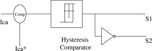
| (iii) | Hysteresis Current Controller: Hysteresis current controller shown in Figure generates PWM signal by comparing the reference signal w.r.t to the actual signal the figure below shows the generation of PWM signal by comparing the two current signals. | ||||
7. Result analysis
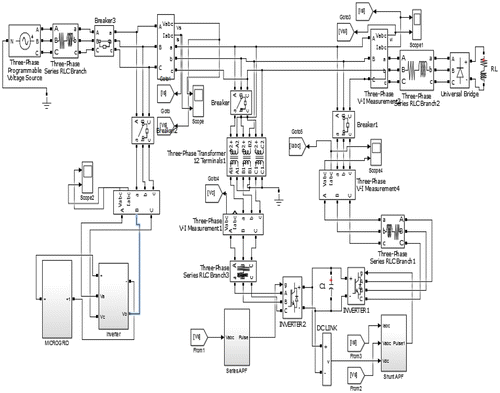
The Figure represents the block diagram of Microgrid (PV/Fuel cell/wind energy) system where the DC voltage of each energy source is connected to a common bus i.e. DC Bus and then it is converted to AC by using an inverter. Microgrid/grid with -UPQC is simulated in Matlab which is shown in Figure , which consist of series APF, shunt APF, Solar PV, Fuel cell, Wind energy conversion system, boost converter and inverter. Moreover, most of the control strategies in literatures only focus on grid connected system whereas in Microgrid system the design of controller is often neglected. This paper combines both Microgrid and grid connected system and verifies the power quality issue at PCC considering disturbance at both side. The different parameter for performing the simulation work is shown in Tables and .
Table 1. Different parameters and their ratings to carry out the simulation process for UPQC
Table 2. Different parameters and their ratings to carry out the simulation process of fuel cell
The circuit will operate in two modes, in the 1st mode grid is connected with nonlinear loads and the power quality problem i.e. sag, swell and harmonics are verified without and with UPQC. The observations made during the study are given below.
| • | The simulation result shown in Figure clearly shows the voltage sag from 0.1 to 0.3 sec without UPQC. When the UPQC injects voltage from 0.1 to 0.3 sec shown in Figure , the load voltage is compensated and exactly equal to that of source voltage. The Figure shows the load voltage after compensation. | ||||
| • | Harmonics compensation is an important issue for a grid and Microgrid connected system as per the literatures and IEEE standard the harmonics should be below 5% in case of load current connected to non-linear load. | ||||
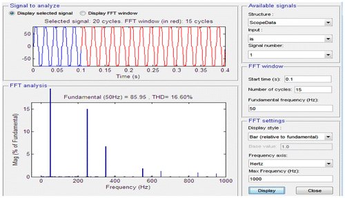
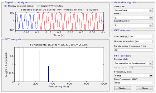
| • | The simulation result of load current without UPQC is shown in Figures and shows its harmonics content i.e. 16.6% by using FFT analysis due to the non-linear load. When the UPQC injects compensating current from 0.1 to 0.4 sec as shown in Figure , the load current harmonics is reduce to 2.33%. | ||||
| • | The Figure shows the FFT analysis of load current after compensation and the load current after compensation is shown in Figure . | ||||
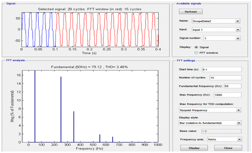
In the 2nd mode microgrid is connected to the AC bus with nonlinear loads and grid is disconnected and then UPQC is operated. It is found from the load current harmonics is reducing from 16.66 to 3.48% which is desirable as per the IEEE standard. The Figure shows the harmonics content by FFT analysis of in Microgrid operated system.
8. Conclusion
The performance of UPQC under different load conditions has been studied and compared with microgrid side disturbances and grid side disturbances, it is observed that the harmonics in load current is reduce below 5% in all cases and also the compensation of voltage sag and swell as shown in Table . The simulation result shows that UPQC connected to grid with nonlinear load can compensate voltage sag, swell and also reduce the load current harmonics to 2.33%. The implementation of microgrid with UPQC makes an advantage that it can compensate all the power quality and also reduce the load current harmonics to 3.48%. From the analysis it is found that UPQC connected to utility and microgrid can compensate all the PQ issues in distribution side. Moreover, in case of any major fault or power disturbance in the main grid, the Microgrid switches over to stand-alone mode while still feeding power to the critical loads effectively.
Table 3. Comparison of harmonic distortion in source current with different load condition
Funding
The authors received no direct funding for this research.
Additional information
Notes on contributors
Sarita Samal
Sarita Samal received her BTech (Hons) in electrical engineering from Berhampur University and her MTech in power system engineering from VSSUT Burla. She is currently pursuing her PhD in VSSUT Burla. Her current research interests include power quality improvement and application of power electronics with non-conventional energy sources.
Prakash Kumar Hota
Prakash Kumar Hota received his BE (Distinction) in Electrical & Electronics Engineering from NIT, Tiruchirapalii, his MSc (Engg.) in Industrial Power Control &Electric Drives from Sambalpur University, odisha, and his PhD (Engg.) from Jadavpur University, Kolkata. He has published over 121 articles in different journals & conferences. He guided seven PhD Scholar and is presently guiding seven scholars in the area of Power System Operation and control, deregulation, Power Quality and Hybrid Generation Systems.
References
- Ahmadi, R., & Ferdowsi, M. (2014). Improving the performance of a line regulating converter in a converter-dominated DC microgrid system. IEEE Transactions on Smart Grid, 5(5), 2553–2563. 10.1109/TSG.2014.2319267
- Altas, I. H., & Sharaf, A. M. (2007). A photovoltaic array simulation model for matlab-simulink GUI environment. In Clean Electrical Power, ICCEP’07 (pp. 341–345).10.1109/ICCEP.2007.384234
- Basu, M., Das, S. P., & Dubey, G. K. (2007). Comparative evaluation of two models of UPQC for suitable interface to enhance power quality. Electric Power Systems Research, 77(7), 821–830.10.1016/j.epsr.2006.07.008
- Benachaiba, C., Haidar, A. M., Habab, M., & Abdelkhalek, O. (2011). Smart control of UPCQ within microgrid energy system. Energy Procedia, 6, 503–512.
- Bucci, G., Ciancetta, F., Fiorucci, E., & Vegliò, F. (2007). An experimental approach to the modeling of PEM fuel cells in dynamic conditions. In Power Tech (pp. 1094–1099).
- Chen, Y., Zha, X., Wang, J., Liu, H., Sun, J., & Tang, H. (2000). Unified power quality conditioner (UPQC): The theory, modeling and application. In Power System Technology, 2000. Proceedings. PowerCon 2000. International Conference on, 3, 1329–1333.10.1109/ICPST.2000.898162
- Femia, N., Petrone, G., Spagnuolo, G., & Vitelli, M. (2005). Optimization of perturb and observe maximum power point tracking method. IEEE Transactions on Power Electronics, 20(4), 963–973.10.1109/TPEL.2005.850975
- Fitzer, C., Barnes, M., & Green, P. (2002). Voltage sag detection technique for a dynamic voltage restorer. Industry Applications Conference, 37th IAS Annual Meeting. Conference Record of the, 2, 917–924.
- Ghosh, A., & Ledwich, G. (2009). Power quality enhancement using custom power devices. New Delhi: Springer Int. Ed.
- Hatziargyriou, N., Asano, H., Iravani, R., & Marnay, C. (2007, July/Augest). Microgrids. IEEE Power and Energy Magazine, 5(4), 78–94. 10.1109/MPAE.2007.376583
- Jain, S. K., Agarwal, P., & Gupta, H. O. (2003). Simulation and experimental investigations on a shunt active power filter for harmonics and reactive power compensation. IETE Technical Review, 20(6), 481–492.10.1080/02564602.2003.11417108
- Jamil, M., Gupta, R., & Singh, M. (2012). A review of power converter topology used with PMSG based wind power generation, In Power India Conference, 2012 IEEE Fifth, 1–6.
- Kesler, M., & Ozdemir, E. (2011). Synchronous-reference-frame-based control method for UPQC under unbalanced and distorted load conditions. IEEE Transactions on Industrial Electronics, 58(9), 3967–3975.10.1109/TIE.2010.2100330
- Koutroulis, E., & Kalaitzakis, K. (2006). Design of a maximum power tracking system for wind-energy-conversion applications. IEEE Transactions on Industrial Electronics, 53(2), 486–494.10.1109/TIE.2006.870658
- Lee, G. M., Lee, D. C., & Seok, J. K. (2004). Control of series active power filters compensating for source voltage unbalance and current harmonics. IEEE Transactions on Industrial Electronics, 51(1), 132–139.10.1109/TIE.2003.822040
- Montero, M. I. M., Cadaval, E. R., & Gonzalez, F. B. (2007). Comparison of control strategies for shunt active power filters in three-phase four-wire systems. IEEE Transactions on Power Electronics, 22(1), 229–236.10.1109/TPEL.2006.886616
- Nergaard, T. A., Ferrell, J. F., Leslie, L. G., & Lai, J. S. (2002). Design considerations for a 48 V fuel cell to split single phase inverter system with ultra capacitor energy storage. Power Electronics Specialists Conference, Pesc 02, 4, 2007–2012.
- Noroozian, R., Abedi, M., Gharehpetian, G. B., & Bayat, A. (2010). On-grid and off-grid operation of multi-input single-output DC/DC converter based fuel cell generation system. In Electrical Engineering (ICEE), 2010 18th Iranian Conference on, 753–758. 10.1109/IRANIANCEE.2010.5506975
- Olivares, D. E., Mehrizi-Sani, A., Etemadi, A. H., Cañizares, C. A., Iravani, R., Kazerani, M., … Jimenez-Estevez, G. A. (2014, July). Trends in microgrid control. IEEE Transactions on Smart Grid, 5(4), 1905–1919. 10.1109/TSG.2013.2295514
- Singh, B., Al-Haddad, K., & Chandra, A. (1999, October). A review of active filters for power quality improvement. IEEE Transactions on Industrial Electronics, 46(5), 960–971. 10.1109/41.793345
- Singh, B., Chandra, A., & Al-Haddad, K. (2015). Power quality: Problems and mitigation techniques. Chichester, West Sussex: Wiley.
- Suresh, M., Patnaik, S. S., Suresh, Y., & Panda, A. K. (2011). Comparison of two compensation control strategies for shunt active power filter in three-phase four-wire system. In Innovative Smart Grid Technologies (ISGT), IEEE PES, 1–6.
- Tafticht, T., Agbossou, K., Cheriti, A., & Doumbia, M. L. (2006). Output power maximization of a permanent magnet synchronous generator based stand-alone wind turbine. Industrial Electronics, 2006 IEEE International Symposium on, 3, 2412–2416.10.1109/ISIE.2006.295950

