 ?Mathematical formulae have been encoded as MathML and are displayed in this HTML version using MathJax in order to improve their display. Uncheck the box to turn MathJax off. This feature requires Javascript. Click on a formula to zoom.
Abstract
In this work, a method is proposed for the calculation of the electromagnetic field radiated by a grounding system in a semi-infinite dissipative medium subjected to a current excitation generated by the lightning strike. The assessment of the induced current distribution on the grounding system due to a transient excitation is obtained by solving Pocklington’s equation using the method of moments. A new method for the calculation of the transient electromagnetic field following the injection of a lightning current or short circuit is also developed. This method is based on the concept of the hertzian dipoles and the asymptotic expansion of a single dipole. A MATLAB computer program has been developed for the determination of the induced currents. The program is validated by comparing its results with those obtained with the commercial software NEC 4.
Public Interest Statement
When lightning strikes an object on the ground, a large amount of electric current flows from the cloud to the object in less than one thousandth of a second, causing a multitude of effects ranging from mechanical damage, overheating, biological effects on humans and livestock, to indirect effects in the form of induced voltages in nearby metallic structures. This paper intends to contribute in better assessing such effects on metallic grounding systems buried underneath electrical installations, by proposing a method to compute the electromagnetic (EM) radiation generated by the flow of such large current. Evaluation of the EM radiation is of value in assessing the safety risks due to exposure of working persons and people to induced lightning effects, and also in evaluating the impact on sensitive electronic equipment. It can also help electric utility companies design better mitigating measures to protect the community.
1. Introduction
The increasing use of sensitive electronics and digital technologies in power system equipment has raised significant interest in power system electromagnetic compatibility studies.
When lightning hits an electrical substation, large currents generated by the stroke flow in the above ground structures and dissipate in the soil through the substation grounding system. The electromagnetic fields generated by such high currents may cause damage to equipment and may be dangerous to personnel working nearby.
For this purpose, many researchers have developed different models for analyzing the transient behavior of grounding systems under lighting strikes. These models can be classified as circuit approach (Araneo et al., Citation2015; Celli, Ghiani, & Pilo, Citation2010; Gatta, Geri, Lauria, & Maccioni, Citation2014; Geri, Citation1999), transmission-line approach (Gazzana et al., Citation2014, Citation2017; Kherif, Chiheb, Teguar, Mekhaldi, & Harid, Citation2017; Liu, Theethayi, & Thottappillil, Citation2005; Lorentzou, Hatziargyriou, & Papadias, Citation2003; Theethayi, Baba, Rachidi, & Thottappillil, Citation2008), and electromagnetic field approach (Karami, Sheshyekani, & Rachidi, Citation2017; Li, Li, Fan, & Yin, Citation2011; Poljak, Sesnic, Cavka, & Drissi, Citation2012; Qi, Cui, Zhao, & Li, Citation2007; Zhang, Cui, Zhao, Yin, & Li, Citation2003).
The electromagnetic field approach is the most rigorous method for modelling the transient behaviour of a grounding system. It solves the full set of Maxwell’s equations with minimum approximations. This approach can be implemented either by the Method of Moments (MOM) or by the Finite Element Method (FEM). In all above-mentioned models, the effect of lossy ground is taken into account using the modified image theory or by approximation in Sommerfeld integrals. This implies that if the effect lossy ground is ignored it leads to erroneous results in predicted electromagnetic fields.
The electromagnetic fields radiated by a grounding system above a semi-infinite dissipative medium subjected to a current excitation generated by the lightning strike are evaluated using the concept of the Hertzian dipoles. In this method, the effect of lossy ground is taken into account by the Sommerfeld integrals (Sommerfeld, Citation1949; Ye & Jin, Citation2010). This reflects the effect of finite conductivity of the interface, which requires a correction term, due to the air-soil interface, for the complete solution of the electric field. In addition, the Sommerfeld integrals depend on the horizontal distance r, measured parallel to the interface between the source and observation point and on the vertical distance between the observation point and the source image. There are many published numerical and analytical techniques dealing with the integrals arising in the Sommerfeld half-space problem, which have been reviewed in Chatterjee, Rao, and Kluskens (Citation2016), Hochman and Leviatan (Citation2010), Rahmat-Samii, Mittra, and Parhami (Citation1981). Subsequently, a comprehensive formulation on the development of the lossy half-space problem, using Hertz potentials, was given by Banos (Citation1966). The solution was expressed in terms of the solutions of the two basic Sommerfeld integrals V1 and U1, which are evaluated by numerical integration along contours in the complex plane and used subsequently to obtain the integral values needed for the integral equation solution using the method of moments.
Modeling this problem for the quantification of radiated electromagnetic fields resulted in the proposal of some computational approaches, especially in the frequency domain. The best known in this area is the one that uses the antenna theory.
In this paper, we analyze the performance of grounding system subjected to a lightning strike using a two-stage approach. In the first stage, a model of the grounding system is developed, and in the second, the electromagnetic field radiated by the grounding system under impulse current is computed. The solution is obtained using antenna theory and the method of moments, in the case of direct injection of a lightning current. In this procedure, the lightning current waveform is described using Heidler’s formula, and is injected at one point of the grid. The grid’s transient response is computed in the frequency domain by solving the electromagnetic field integral equation. The temporal and spatial distributions of the electromagnetic field near the grounding system are obtained by the inverse Fourier transform (Song & Chen, Citation1993). The proposed approach is applied to the case of a horizontal conductor buried in uniform soil and a grounding grid. To validate the approach, the results are compared with those obtained using the commercial software NEC-4 (Burke, Citation1992).
2. Analytical expressions for dipole in infinite conducting medium
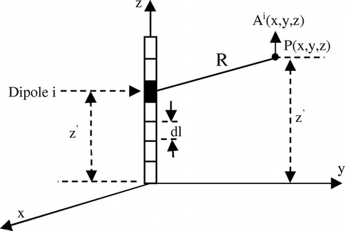
The method consists of subdividing the wire structure element into small elements called dipoles (Figure ), whose size is chosen in order to mask the propagation.
The field at any point of the medium is obtained by superimposing the contributions of all dipoles.The size of the dipoles “dl” must meet the following two conditions:(1)
(1)
where λ is the smallest significant wavelength. This condition can mask the propagation along the dipole; the current amplitude and phase along the dipole are independent of z.(2)
(2)
where R is the distance between the dipole under consideration and the observation point.
This condition can take into account small variations in current from a point very close to the wire structure.
In his work, Sivaprasad and King (Citation1963) provides compact expressions for calculating the field radiated by a dipole located in a semi-dissipative medium. In harmonic regime and cylindrical coordinates, the electromagnetic field created by a horizontal dipole in a semi-infinite medium is expressed in terms of Sommerfeld integrals.
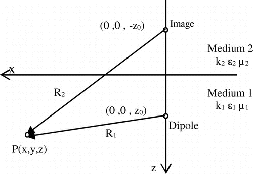
The electromagnetic fields of a horizontal dipole in a semi-infinite medium, due to a source are expressed in terms of the solutions of the two basic integrals V1 and U1. The derivations of the expressions of the field are given in Harrigton (Citation1968) using cylindrical coordinates (r, θ, z).
The rigorous expressions for the r, θ and z-components of the electric and magnetic field at a near point due to a source current, in a local cylindrical coordinate system illustrated in Figure , are (Harrigton, Citation1968):(3)
(3)
(4)
(4)
(5)
(5)
(6)
(6)
(7)
(7)
(8)
(8)
where(9)
(9)
(10)
(10)
: Hankel function.
The electric and magnetic field at a point near the grounding system is the sum of contributions from the overlapped sinusoidal current sources in all segments. Asymptotic solutions obtained in Lytle and Lager (Citation1974) and Sivaprasad (Citation1962) may be used if the following conditions are satisfied (Lytle & Lager, Citation1974):
| (1) | The source and the receiver are close to the interface. | ||||
| (2) | The refractive index | ||||
| (3) | k1 is complex and has a large attenuation constant. | ||||
| (4) | Re(k1r) >> 1 and k2r > 1. | ||||
3. Computation of the transient current distribution in a grounding system
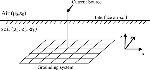
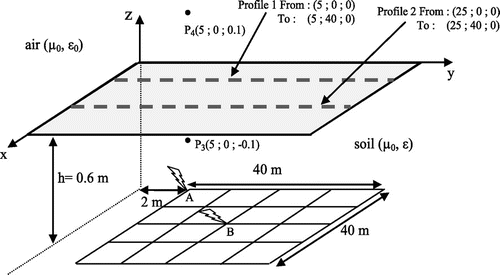
The geometry of interest, shown in Figure , is a grounding grid system composed of interconnected conductors.
The grounding system is assumed to be a network of interconnected straight cylindrical metallic conductors with arbitrary orientation and finite conductivity. The conductors are subject to the thin-wire approximation, assuming that their radiuses are much smaller than the wavelength and their lengths are much greater than the radiuses.
The integral-differential equation of the Pocklington type for the unknown current I(r′) induced along the thin wire of an arbitrary shape buried in a lossy half-space is given by:(11)
(11)
where G(r, r′) is the corresponding Green’s function:(12)
(12)
Es: the total scattered electric field along the surface of the conductor.
t′: the unit vector along wire axis, t′
I(r′): the current flowing along the conductor.
G(r, r′): the dyadic Green’s function for an unbounded medium with that corresponding to a half-space conducting medium.
g0(r, r′) and gi(r, r′) are Green’s dyadic functions for the electric field at r due to the current element and its image.
The third and last term gsu(r, r′) is a correction term necessary for the complete solution of the electric field.
4. Validation: Buried horizontal electrode
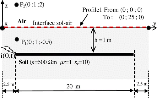
In order to validate the approach we propose for calculating the transient electromagnetic field emitted by a ground electrode, we consider a 20 m horizontal electrode of 0.07 m radius excited by a lightning current. For this application, a computer program was developed in MATLAB and the results are compared with those obtained with the Numerical Electromagnetic Code (NEC-4). Figure shows the horizontal conductor in homogeneous soil with a resistivity 500 Ωm, buried at a depth h = 1 m. The soil’s relative permittivity and relative permeability are assumed equal to 10 and 1 respectively. The electrode is energized at one end by a lightning current having a waveform described by Heidler’s formula, as recommended by international standards on lightning protection (IEC 61312-1, Citation1995; ITU-T Recommendation K.40 (10/96), Citation1996):(13)
(13)
where I = 10.7 kA current peak value, η = 0.93 correcting factor, τ1 = 19 μs, τ2 = 0.8 μs – front and tail time constants.
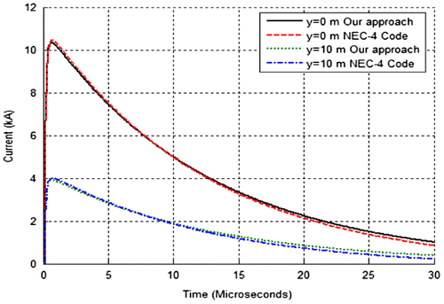
The results illustrated in Figure show the current at the injection point and at 10 m along the electrode length obtained by the proposed model and by NEC-4. For the two points of the electrode, we note a perfect agreement in amplitude and shape, particularly on the rising front (i.e. at the highest frequencies) with a slight difference on the impulse tail. This can be explained by the fact that our approach uses an impulse function as test function (point-matching method) while the software NEC-4 uses sinusoidal functions as test functions. Both results show that half-way through the electrode, more than 50% of the current have dissipated into the surrounding soil.
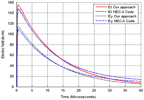
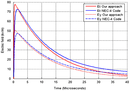
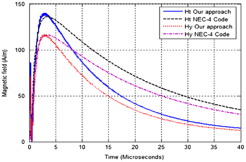
Figures and show the total radiated electric field Et and y- components of electric fields Ey computed at points P1 (in the soil) and P2 (in the air) respectively. As can be seen in Figure , there is satisfactory agreement between the proposed approach and the results obtained with NEC-4, with a slight over estimation of the peak values compared to NEC-4 results. Above ground (point P2), a similar difference is observed with magnitudes but a somewhat faster rising time is predicted by the proposed approach. The difference may be due to the choice of the segment length introducing inaccuracies. The magnetic fields show better concordance with the NEC method on the rising impulse front, and significant differences on the tail, as shown in Figure .
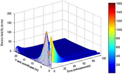
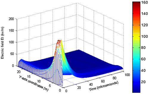
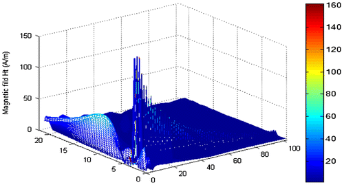
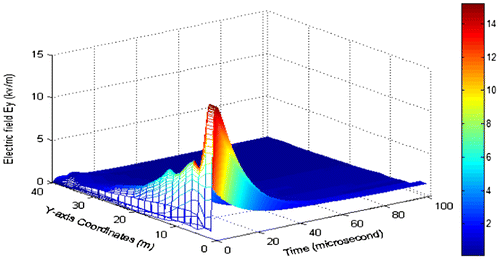
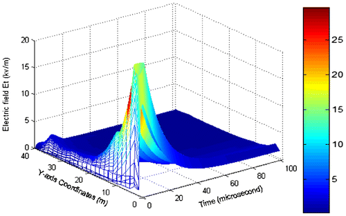
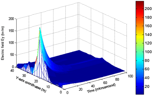
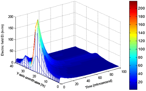
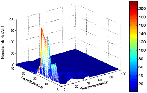
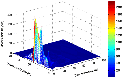
Figures and show the time-domain y-component of electric field and total electric field, respectively, at the earth’s surface, along the selected profile. For the typical lightning impulse current, the electric field on the earth surface can reach up to 1.5 kV/cm or higher at the point of energization. Figure shows the temporal variation of the magnetic field on the earth’s surface, along the y-direction profile shown in Figure . Magnitudes of more than 140 A/m can be generated as a result of the lightning impulse current, corresponding to a peak magnitude field density of approximately 176 μT. The computed values of electric and magnetic field are in excess of the reference limits defined by ICNIRP (ICNIRP, Citation1998) for the frequencies that are within the lightning frequency spectrum.
5. Case of a grounding grid
The substation grounding system consists of an above-ground structure bonded to a 40 × 40 m, 16-mesh square ground grid buried at a depth of 0.6 m. The soil is assumed to be homogeneous with a 500 Ωm resistivity, a relative permitivity of 10, and relative permiability of 1. The grid is energized by a lightning current waveform described with Heidler’s formula given in Equation (Equation13(13)
(13) ). Two injection points were considered: first at one corner of the grid and then at the centre point of the grid. This surge current gradually dissipates in the soil while travelling along the conductors of the structure and ground grid. Simultaneously, strong electromagnetic fields are generated both in the air and in the soil. The grid configuration shown in Figure is considered, and the electromagnetic field is computed at points P3 and P4.
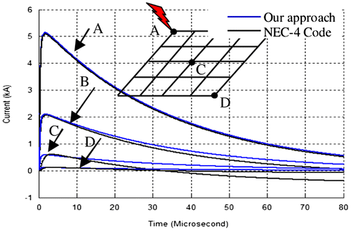
Figure shows the transient current at four points “A”, “B”, “C” and “D” in a 40 × 40 m grid with 10 m long ground rods at the corners, subjected to current impulse injected at point “A”. As expected, a large proportion of the current dissipates to ground as it travels along the grid conductors, and only a very small proportion reaches point D, furthest from the injection point. Close agreement is obtained between the present approach and the NEC-4 Code computations at the feeding point, with slight differences between at points “B”, and “D”.
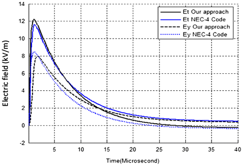
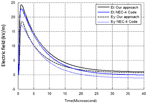
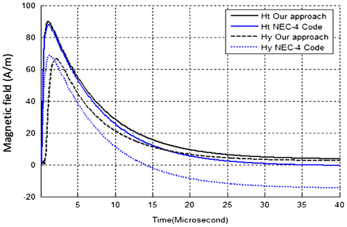
The radiated electric field at point P3 (in the soil) and P4 (in the air) are shown in Figures and respectively. The magnitudes of the radiated fields are comparable with those given by the NEC-4 Code, although the wave shapes show some differences. For assessing the level of exposure of the personnel and the public, the magnitude is the most relevant parameter that is considered for a given impulse current. Figure shows the temporal evolution of the y-component of magnetic field intensity Hy and total field intensity Ht, computed at points P3 (in the soil) using the two computation methods. Reasonable agreement is obtained for the total magnetic field, whereas a time delay is observed between the two methods in the computed y-component of the magnetic field.
5.1. Current injection at corner point A
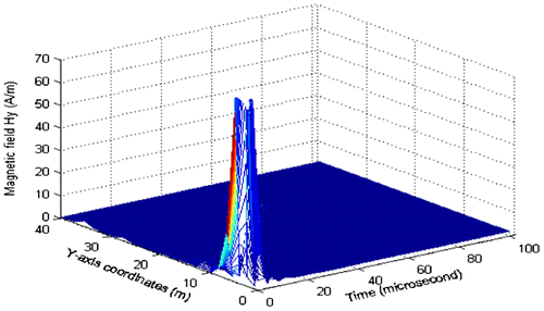
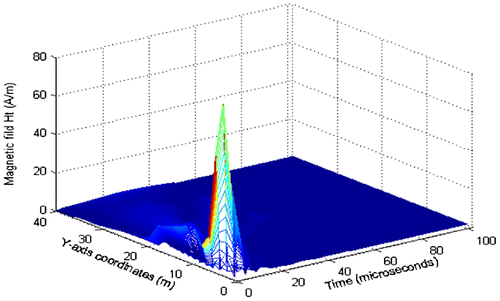
Figures show the temporal evolution of the electric and magnetic field intensity respectively on the earth’s surface when the lightning surge current is injected at corner point A. The induced field is maximal at the injection point, falling rapidly with distance away from the grid’s corner. The fall in magnetic field with distance is much sharper, reducing to zero withinn the first 10 meters from the corner point.
5.2. Current injection at center point B
Figures – show the results obtained when the impulse current is injected at the middle point on the grid’s periphery (point B).
As can be seen from these figures, much higher electromagnetic fields are radiated near the centre injection point compared with the corner injection point. This result shows that, for given site conditions, the emitted electromagnetic fields due to lightning currents flowing in grounding systems depend not only on current magnitude, but also on the location of the point of lightning strike. Note that the field radiated by the grounding grid is lower than that radiated by a single electrode (Figure ), which is expected since the flow of fault between the two is different. For the grid, the branching of current through the mesh causes a reduction in the induced electromagnetic field.
6. Conclusion
The fundamental concepts and analytical development for the quantification of the electromagnetic field radiated by a grounding system in semi-infinite dissipative medium subjected to a current excitation generated by the lightning strike in a conducting half-space are described and discussed. A method is proposed based on the computation by Hertzian dipole concept in frequency domain of the scattered electric and magnetic field in the vicinity of the grid. The solution was given in terms of the solutions of two basic Sommerfeld integrals. These are evaluated by numerical integration along contours in the complex plane and used subsequently to obtain the Sommerfeld integral values needed for the moment method solution of an integral equation. The latter requires knowledge of the current distribution. To this end, the integral equation is solved for the electric field by the method of moments in the frequency domain.
The proposed method was applied to a horizontal electrode and a grounding grid to address the problem of computing the transient electromagnetic radiation of a grounding system. The results are compared with those computed using the NEC-4 code with acceptable agreement.
The results demonstrate that the proposed method can be used as a tool to estimate the electromagnetic fields and associated EM energy radiated in the vicinity of grounding systems, and to assess safety thresholds for persons and equipment. It can also be used to determine the sub-surface distribution of electromagnetic fields, useful for estimating the impulse performance of grounding systems and the occurrence of soil ionisation phenomena in grounding system design studies.
This approach can be refined to improve accuracy. It can be further validated by performing further comparisons with other established software packages. It can also be applied to compute the radiated electromagnetic field of a wide range of grounding system configurations.
Funding
The authors received no direct funding for this research.
Additional information
Notes on contributors
N. Harid
N. Harid has been conducting research on grounding systems for the past 15 years, during which he and his colleagues at Cardiff University have secured funding of several million pounds to develop new measurement methods and modelling techniques for assessing the safety risks associated with short-circuit currents and lightning currents flowing in electrical substations’ grounding systems. His research interests include condition monitoring of overhead lines, demand management, application of wireless communications in power systems, high-voltage insulation and power system transients. The collaboration with co-authors has resulted in the work reported in this paper, which, like several other publications by the author on the same topic, relates very well to the ongoing issue of safety and electrocution risks for people living near or working in high-voltage electrical installations. The results of part of the previous research are proposed in a relevant international standard.
References
- Araneo, R., Maccioni, M., Lauria, S., Geri, A., Gatta, F., & Celozzi, S. (2015). Hybrid and pi-circuit approaches for grounding system lightning response. In PowerTech, 2015 IEEE Eindhoven (pp. 1–6). IEEE.
- Banos, A. (1966). Dipole radiation in the presence of a conducting half space. New York, NY: Pergamon Press.
- Burke, G. J. (1992, January). Numerical electromagnetic code –NEC-4, method of moments, Part I. Lawrence Livermore National Laboratory.
- Celli, G., Ghiani, E., & Pilo, F. (2010). Behaviour of grounding systems: A quasi-static EMTP model and its validation. In 30th International Conference on Lightning Protection (ICLP) (pp. 1–6).
- Chatterjee, D., Rao, S. M., & Kluskens, M. S. (2016). Some new techniques for evaluating Sommerfeld integrals for microstrip antenna analysis. In Electromagnetic theory (EMTS), 2016 URSI international symposium on (pp. 335–337). IEEE.
- Gatta, F. M., Geri, A., Lauria, S., & Maccioni, M. (2014). Generalized pi-circuit tower grounding model for direct lightning response simulation. Electric Power Systems Research, 116, 330–337.
- Gazzana, D. S., Bretas, A. S., Dias, G. A., Tello, M., Thomas, D. W., & Christopoulos, C. (2014, February). The transmission line modeling method to represent the soil ionization phenomenon in grounding systems. IEEE Transactions on Magnetics, 50(2), 505–508.
- Gazzana, D. S., Tronchoni, A. B., Leborgne, R. C., Bretas, A. S., Thomas, D. W. P., & Christopoulos, C. (2017). An improved soil ionization representation to numerical simulation of impulsive grounding systems. IEEE Transactions on Magnetics, 1–4. doi:10.1109/TMAG.2017.2750019
- Geri, A. (1999, July). Behaviour of grounding systems excited by high impulse currents: The model and its validation. IEEE Transactions on Power Delivery, 14(3), 1008–1017.
- Harrigton, R. F. (1968). Field computation by moment methods. New York, NY: Macmillan.
- Hochman, A., & Leviatan, Y. (2010). A numerical methodology for efficient evaluation of 2D Sommerfeld integrals in the dielectric half-space problem. IEEE Transactions on Antennas and Propagation, 58(2), 413–431.
- ICNIRP. (1998). Guidelines for limiting exposure to time-varying electric, magnetic and electromagnetic fields (up to 300 Ghz). Health Physics, 74(4), 494–522.
- IEC 61312-1. (1995). Protection against lightning electromagnetic impulse. General principles.
- ITU-T Recommendation K.40 (10/96). (1996). Protection against interference protection against LEMP in telecommunications centers.
- Karami, H., Sheshyekani, K., & Rachidi, F. (2017). Mixed-potential integral equation for full-wave modeling of grounding systems buried in a lossy multilayer stratified ground. IEEE Transactions on Electromagnetic Compatibility, 59(5), 1505–1513.
- Kherif, O., Chiheb, S., Teguar, M., Mekhaldi, A., & Harid, N. (2017, September). Time-domain modeling of grounding systems’ impulse response incorporating nonlinear and frequency-dependent aspects. IEEE Transactions on Electromagnetic Compatibility, 99. doi:10.1109/TEMC.2017.2751564
- Li, Z. X., Li, G. F., Fan, J. B., & Yin, Y. (2011, September). Quasi-static complex image method for a current point source in horizontally stratified multilayered earth. Progress in Electromagnetics Research B, 34, 187–204.
- Liu, Y., Theethayi, N., & Thottappillil, R. (2005, April). An engineering model for transient analysis of grounding system under lightning strikes: Nonuniform transmission-line approach. IEEE Transactions on Power Delivery, 20(2), 722–730.
- Lorentzou, M. I., Hatziargyriou, N. D., & Papadias, B. C. (2003). Time domain analysis of grounding electrodes impulse response. IEEE Transactions on Power Delivery, 18(2), 517–524.
- Lytle, R. J., & Lager, D. L. (1974). Numerical evaluation of sommerfield integrals (Report UCRL 51688). Lawrence Livermore Laboratory.
- Poljak, D., Sesnic, S., Cavka, D., & Drissi, K. E. K. (2012, September). On the analysis of vertical straight thin wire above a lossy ground: Analytical versus numerical solution. In Electromagnetic Compatibility (EMC EUROPE), 2012 International Symposium on (pp. 1–6). IEEE.
- Qi, L., Cui, X., Zhao, Z., & Li, H. (2007). Grounding performance analysis of the substation grounding grids by finite element method in frequency domain. IEEE Transactions on Magnetics, 43(4), 1181–1184.
- Rahmat-Samii, Y., Mittra, R., & Parhami, P. (1981). Evaluation of Sommerfeld integrals for lossy half-space problems. Electromagnetics, 1(1), 1–28.
- Sivaprasad, K. (1962). Asymptotic solution of dipoles in a conducting medium (Tech. Rept. 354). Cambridge, MA: Cruft Lab., Harvard University.
- Sivaprasad, K., & King, R. (1963, November 19). A study of arrays of dipoles in a semi-infinite dissipative medium. IEEE Transactions on Antennas and Propagation, 11(3), 240–256.
- Sommerfeld, A. (1949). Partial differential equations (pp. 246–267). New York, NY: Academic Press.
- Song, J., & Chen, K. (1993, October). Propagation of EM pulses excited by an electric dipole in a conducting medium. IEEE Transactions on Antennas and Propagation, 41(10), 1414–1421.
- Theethayi, N., Baba, Y., Rachidi, F., & Thottappillil, R. (2008, May). On the choice between transmission line and full-wave Maxwell’s equation for transient analysis of buried wires. IEEE Transactions on Electromagnetic Compatibility, 50(2), 347–357.
- Ye, H., & Jin, Y. Q. (2010). Dual GPOF/DCIM for fast computation of Sommerfeld integrals and EM scattering from an object partially embedded in dielectric half-space. IEEE Transactions on Antennas and Propagation, 58(5), 1801–1807.
- Zhang, B., Cui, X., Zhao, Z., Yin, H., & Li, L. (2003, April). An electromagnetic approach to analyze the performance of the substation’s grounding grid in high frequency domain. COMPEL-The international journal for computation and mathematics in electrical and electronic engineering, 22(3), 756–769.

