 ?Mathematical formulae have been encoded as MathML and are displayed in this HTML version using MathJax in order to improve their display. Uncheck the box to turn MathJax off. This feature requires Javascript. Click on a formula to zoom.
Abstract
Passive flow control valves are usually intended to deliver or drain a fluid at a constant rate independently of pressure variations. Microfluidic devices made of a stack of two plates are considered here: the first plate comprises a flexible silicon membrane having through holes while the second plate is a rigid substrate with a cavity, an outlet hole and pillars aligned with the through holes of the membrane. The liquid flows through the holes etched in the membrane and through the gap between the membrane and the pillars. Each gap can be considered as a valve which progressively closes as the pressure increases. Numerical modelling of the fluid dynamics inside the device associated with FEM simulations of the membrane distortion have been performed to design a device that exhibits a constant flow rate in a specified range of pressure. To make the design more reliable, the device characteristics have been optimized using a genetic algorithm, the fitness function taking notably into account machining and alignment tolerances. This algorithm has been finally used to design flow control valves for wearable injectors dedicated to the infusion of viscous drug formulations (hyaluronic acid, adalimumab, golimumab …) at high pressure. Prototypes have been characterized using solutions of 12 and 24 cP. It has been demonstrated experimentally that this technology is suitable to passively infuse biological products at flow rates up to 1 mL/min. The numerical model has then been refined further so as to obtain a good correlation with experimental data.
Public Interest Statement
Passive (battery less) flow control valves are usually intended to deliver or drain a fluid at a constant rate independently of pressure variations. A typical application is the intravenous or intradermic protein infusion for immunotherapy. Using syringes prefilled with such biologics can cause injectability related issues. On-body injectors are therefore the preferred solution to infuse either high volume or viscous drug formulations. A flow control valve in series with the pressurized reservoir limits the risk of leakage, the pain associated with drug overflow and allows a better control of the injection duration. Microfluidic devices made of silicon and glass are considered here. The device characteristics have been optimized using a genetic algorithm. It has been demonstrated experimentally that this technology is suitable to passively infuse viscous (24 cP) biological products at constant flow rates up to 1 mL/min considering reservoir pressure variations of 10 bar or more.
1. Introduction
A passive flow control valve or flow regulator for biomedical applications delivers a constant amount of drug over time independently of pressure variations. The electrical equivalent of such microfluidic device is a current source. Typical examples of flow control devices are proposed by Chappel, Dumont-Fillon, and Mefti (Citation2014) and Zhang et al. (Citation2015).
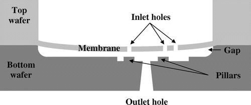
A microfluidic device made of a stack of Silicon-On-Insulator (SOI) and glass wafers is considered here (Figure ). The SOI wafer (Top wafer) has been chosen for the etch-stop potential of the buried oxide. The handle part has a typical thickness of about 400 μm in order to provide stiffness to the valve whereas the device layer is usually thin (typically 30 μm) to serve as a membrane. The etching of the holes in the membrane (SOI front side) is obtained by DRIE (Deep Reactive Ion Etching) to get vertical sidewalls. The silicon membrane is then opened and released from the backside whereas the remaining SiO2 is removed by wet etching.
The substrate wafer (Bottom wafer) is made of Pyrex or Borosilicate. Silicon can also be used as an alternative material but surface quality constraints are much stricter if fusion bonding is targeted to assemble the stack. The cavity defining a gap between the membrane and the pillars after assembly is made either by dry or wet etching. Controlling the depth and uniformity of this gap is critical for the fluidic behavior of the device. The next step consists in an additional etching at the bottom of the cavity in order to create the pillars as well as the fluidic pathway around them to the outlet. Finally, the outlet is created by sandblasting from the backside of the wafer. The final process step consists in an anodic bonding of the two machined wafers.
A typical low pressure application is the derivation of cerebrospinal fluid from the brain ventricles toward the peritoneum. Conversely high pressure applications include, for instance, intravenous protein infusion for immunotherapy. Using prefilled syringes can cause problems with the injectability or syringeability of such biologics. On-body injectors are therefore the preferred solution to infuse either high volume or viscous drug formulations. Depending on the technology used to pressurize the fluid, it could be relevant to add a flow control valve to the device. This additional valve actually limits the risk of leakage induced by overpressure, the pain related to drug overflow and allows a better control of the injection duration.
The dimensioning of the valve to get the expected flow regulation profile is made step by step (Chappel et al., Citation2014). This iterative process starts with the positioning of a first valve located on the outer edge of the membrane. This valve is intended to determine the high pressure fluidic characteristics of the device. Additional valves located near the center of the membrane are then introduced to gradually define the expected flow rate profile at lower pressures. There are potentially a large number of valve configurations that meets the requirement for the targeted flow rate profile. Therefore, in order to find an optimum configuration, there is a need to establish design rules to sort them. Instead of mimicking the manual iterative design phase described above, we have considered a genetic algorithm that is especially adapted to solve complex problems with a large number of variables.
The key parameters to achieve delivery accuracy within the range ±10% are respectively: the membrane thickness, the gap depth, the hole diameters and the alignment between the holes and the pillars. The two first parameters can be easily controlled by using SOI wafers. The impact of the other machining or alignment tolerances on delivery accuracy shall be reduced to the maximum by design. Instead of trying to reduce further the tolerances, we chose to improve the valve design in order to make it more reliable. But, given the complexity of this optimization problem, a specific program has been developed in order to take into account machining tolerances and flow regulation specifications.
This paper aims to demonstrate that flow control valves based on MEMS technology is suitable for the infusion of viscous drug formulations at high pressure. In addition, modelling tools are provided to adapt the design to the injection requirements.
After a presentation of the numerical modelling, the genetic algorithm is briefly described. Using this original design tool, passive flow control valves for delivery of viscous solutions of 12 and 24 cP have been conceived and fabricated in clean room. After a complete metrology of the samples, a fluidic characterization has been carried out and the experimental results are compared to simulations to refine the numerical modelling.
2. Valve modelling
Microvalves are the key elements of MEMS micropumps and other microfluidic systems. Reviews of the different valve technologies are provided by Oh and Ahn (Citation2006) and Au, Lai, Utela, and Folch (Citation2011). A comprehensive mathematical description of fluidics in microvalves is required when the dynamic of the valve opening has an impact on the device behavior. Several analytical formulae related to laminar fluid flow through annular valve are proposed here since such configurations are not fully addressed in classical textbooks of fluid mechanic (see for instance Bird, Stewart, & Lightfoot, Citation2007; Guyon, Hulin, & Petit, Citation2001; White, Citation1991 for detailed descriptions of many solutions to the Newtonian viscous-flow equations). These formulae have been implemented in simulation models for passive flow control valves. Non-idealities like valve tilt and misalignment have been also considered in order to build a model accounting for realistic manufacturing conditions. Finally, to account for the specific geometry of the valves, notably for the transition between the hole and the diffuser, corrective factors have been introduced into the original model (Chappel et al., Citation2014). The singular losses now include a better description of the bend of the flow between the hole and the diffuser as well as the radial flow expansion inside the diffuser itself. Additionally the flow constriction between the hole and the diffuser has been better simulated simply by using a corrective multiplication factor equal to ε = 0.6 for the inner radius of the diffuser itself. These corrections are based on the experimental analysis of specific valves containing only a single centered hole. This investigation has been conducted using Silicon-On-Insulator wafers having device layers of 30 and 129.5 μm respectively to form membranes (from 3.76 to 5.12 mm in diameter) and Pyrex wafers for the substrate and pillars. Both wafers have then been anodically bonded together after alignment. The target gap was fixed to 10.46 μm. The ratio between pillar and hole radii varies from 1.25 to 2.8. The fluidic chips have been tested using water at Reynold numbers comprised in the range 0.5–35. A detailed description of this experimental plan is provided elsewhere (Musard, Dumont-Fillon, van Lintel, & Chappel, Citation2018).
2.1. Axisymmetric case
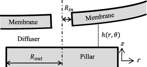
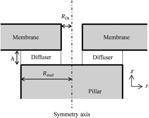
The annular valve geometry considered here consists of a flexible membrane having a hole of radius Rin and a pillar of radius Rout as depicted in Figure . Fluid flows through the hole and the small gap between the pillar and the membrane (diffuser). The opening of this diffuser is usually a function of the pressure gradient through the valve. We consider a power law or Ostwald de Waele fluid relationship between the shear stress σ and the shear rate where the apparent dynamic viscosity η can be approximated by:
Figure 2. Cross-section of axisymmetric annular diffuser geometry (the origin of the axis is located along the pillar axis).
(1)
(1)
where n and m in Equation (1) are two empirical curve-fitting parameters, n = 1 corresponding to Newtonian fluids. The incompressible fluid flow is assumed to be fully developed at the diffuser entrance and the pressures Pin and Pout outside the diffuser are considered as homogenous.
According to the diffuser symmetry, the small value of the gap h and the nature of the fluid, four assumptions are made regarding this flow:
| (1) | Steadiness (∂/∂t = 0). | ||||
| (2) | Axisymmetry (∂/∂θ = 0 and | ||||
| (3) | The vertical velocity is neglected (uz = 0). | ||||
| (4) | Small laminar | ||||
(2)
(2)
The Navier-Stokes equations coupled to the boundary conditions:
(3)
(3)
Yield the fluidic resistance as a function of the flow rate
:
(4)
(4)
Following the value of n, two different expressions are derived as shown in Equations (5) and (6) depicting the function :
(5)
(5)
(6)
(6)
Detailed derivations are provided in the Appendix A. FEM simulations corroborate these calculations with a relative error of less than 0.3% for .
2.2. Non-idealities
Two non-idealities have been introduced into the model:
| • | the misalignment between the hole of the membrane and its facing pillar; | ||||
| • | the tilt of the membrane with respect to the pillar. | ||||
The surface of the pillar is considered as the reference plane z = 0. The membrane center is noted O. Two off-axis parameters δ and are also introduced to account for machining tolerances and wafer misalignment if the valve is a stack of two wafers:
| • | δ is equal to the distance between the pillar center Op and the projection | ||||
| • |
| ||||
Figure 3. Geometry (right) and new coordinates (left) for a misaligned diffuser (top view), the angles being conventionally measured counter clockwise.

The dimensionless parameter used to evaluate the misalignment error is . The term
indicates the direction of the error: for
the hole is closer to the centre of the membrane, for
the hole gets closer to the periphery of the membrane.
Note that if ,
is useless as the direction of misalignment does not influence the local height.
Tilt shall be considered when the pillar is not centered with respect to the flexible membrane or in case of particle contamination preventing a correct closure of the valve. This induces a non-homogeneous distance between the membrane and the pillar h(r, θ) as seen in Figure .
As the deformation of the membrane is likely to be planar above the pillar (membrane diameter >> pillar diameter), a constant tilt angle ψ will be considered in the following study, which results, in considering both kinds of non-idealities, in a distance membrane-pillar of:
(7)
(7)
where h0 is the distance between the membrane without hole and the centre of the pillar. An interesting non-dimensional parameter accounting for the influence of this tilt is . If ξ ≥ 1 there is contact at some point on the pillar, this will be studied later on.
Another system of coordinates is also introduced for further description of the problem in order to keep the origin in the center of the hole. Thus, the link between the old and the new
can be written as:
(8)
(8)
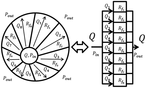
The total fluidic resistance is estimated through a parallelization of infinitesimal fluidic resistances around the diffuser as depicted in Figure .
The discrete and continuous versions of such a calculus would be
(9)
(9)
And
(10)
(10)
where represents the infinitesimal fluidic resistance between the angles θ and
. It can be computed as the resistance per angle for a diffuser with an axisymmetric height. This latter value is obtained by summing numerically the resistance:
(11)
(11)
where r′ and θ′ are defined in function of r and θ in Equation (8) and is the partial derivative of Equations (5) and (6) evaluated in h(r′, θ′) and
(see the Appendix A for the explanation related to the different exponents used in Equation (11), for an axisymmetric variable height). Finally, Rmax(θ) is the exit radius “in front of” the angle θ on Figure and can be evaluated as:
(12)
(12)
Note also that Equation (11) can be calculated analytically in the case of Newtonian fluid (n = 1).
Finally, in case of contact between the pillar and the membrane (ξ ≥ 1), the integration range in Equation (10) is reduced. For small misalignments () and closing angles (ξ ≤ 1.2), correlations between the numerical modelling and FEM simulations exhibit deviations better than 15% with the estimated fluidic resistances, in the same range 0.5 < n < 2.
3. Genetic algorithm
Conventional optimization algorithms, like gradient-descent, become very complex for multivariable and non-linear systems. Some bio-inspired algorithms are being increasingly used to solve complex problems (Floreano & Mattiussi, Citation2008). Based on Darwinian principles, a genetic (or evolutionary) algorithm relies on random mutation, selection and reproduction of the best individuals (being valves in our case) over generations.
In the algorithm, each individual (valve) is described by a genotype (set of parameters): number of holes and pillars, hole position and diameter, pillar position and diameter. These parameters vary from one valve to the other and may change during mutations. Other characteristics like the global geometry of the device or the membrane thickness are kept constant. These parameters are initially defined by simple consideration on the regulation pressure range, burst pressure and fluidic interconnection issues.
A population of N = 20 valves is initially generated randomly. Two models have been developed: a finite element model to compute the membrane deflection as a function of pressure, and an analytical fluidic model, to derive the flow rate from a given set of deflection and pressure. By combining these two models, it is possible to determine the flow going through a valve for a given pressure applied on the membrane. The fitness function is a measure of the valve performance, like a grade. It is used to determine which are the best individuals to be selected and reproduced for the next generation (Dumont-Fillon, Hannebelle, van Lintel, & Chappel, Citation2016).
The fitness function is set to measure two main parameters:
| • | Proper flow control: its flow curve must be as close as possible to a target value in a given range of pressure. | ||||
| • | Sensitivity to micro-machining tolerances. | ||||
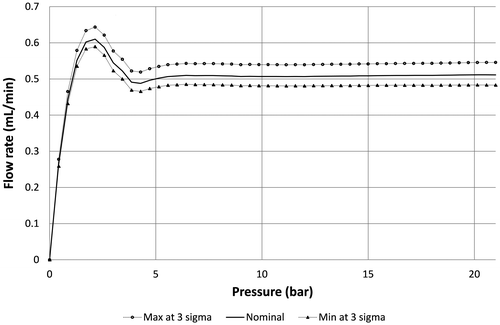
The sensitivity to machining tolerances is obtained by performing a fluidic simulation of the design not with the ideal but altered dimensions, taking into account the misalignment and worst combination of tolerances at 3σ for all the critical dimensions that impact the flow rate, including the membrane thickness and radius, the hole and pillar diameters as well as the gap value. A typical example of fluidic characteristics after optimization is provided in Figure , considering a maximum misalignment of 5 μm and tolerance of ±0.5 μm at 3σ for the critical dimensions listed here above except for the gap (). It is shown that an error on the flow rate of about ±8% is expected at 3σ.
Figure 6. Simulation of the impact of process tolerances at 3 sigma on the flow profile of a valve designed to deliver a constant flow rate of 0.5 mL/min at 24 cP in the range 7–21 bar.
Since the validity of this model determines the validity of the design generated by the algorithm, it has been validated on fabricated valves (Chappel et al., Citation2014). Another validation for valves exhibiting very small gaps even at low pressure has been conducted recently to tune the fluidic model. It has been inferred that FEM simulations tend to overestimate the membrane stiffness after contact with the pillars. The estimation of the gap between the hole and the pillar as a function of the pressure includes therefore some corrections based on experimental data too. Microfluidic diffusers as described in (Musard et al., Citation2018) have been machined in a similar way, using exactly the same dimensions except for the radial position of the diffuser along the membrane radius. By using the fluidic model described in (Musard et al., Citation2018) and comparing the fluidic characteristics of out-of-center and centered diffusers, it has been possible to refine the estimation of the gap for different radial positions as a function of the applied pressure, using a fluidic characterization of the diffusers.
4. Design description; microfabrication and metrology
Three different designs have been made for infusing newtonian viscous fluids, in the pressure range 5–20 bar, according to the target flow rates provided in Table . For the two solutions at 12 and 24 cP, obtained by mixing glycerol and water (see Table for the glycerol fraction mass), densities of 1.145 and 1.170 have been respectively introduced in the model according to (Segur & Oberstar, Citation1951).
Table 1. Target flow rates at 20°C for the designs A, B and C
Table 2. Physical characteristics of the water/glycerol mixtures of 12 and 24 cP according to Segur and Oberstar (Citation1951)
The silicon membranes have been made using SOI wafers having a device layer 130 μm thick (129.5 μm after oxidation) in order to sustain pressures up to 35 bar. The gap has been fixed at 10.46 μm. All membrane diameters are equal to 5.12 mm. The height of the pillars is 50 μm and the outlet hole has a diameter of 500 μm. Overall chip dimensions are 10 × 10 mm.
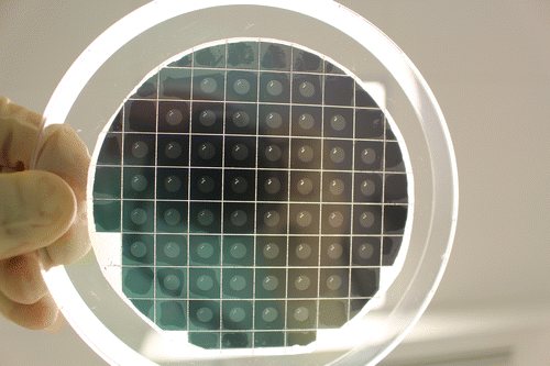
The process flow is similar to the one described in (Chappel et al., Citation2014). Microfabrication has been carried out at CMi (EPFL, Switzerland). A photo of a 4′′ wafer after dicing is provided in Figure .
The hole and pillar dimensions have been carefully characterized using the microscope Nikon Eclipe LV150 associated to the software Kappa Metreo. The targeted and measured hole and pillar dimensions are provided for each design in Tables and respectively. The values indicated by the software have been reported here with all digits even if they are not really significant because of the measurement repeatability estimated at 0.5 μm. The goal of the Tables and is just to show that both holes and pillars are within the specifications at ±1 and ±5 μm respectively.
Table 3. Comparison between theoretical and measured hole diameters for each design
Table 4. Comparison between theoretical and measured pillar diameters for each design
5. Experimental setup and test methods
5.1. Test setup
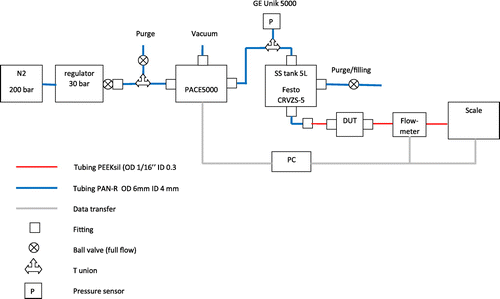
The layout of the test setup, as provided in Figure , comprises a 20L pressurized bottle (4.5 nitrogen at 200 bar) associated with a first pressure regulator (Gloor) that maintains at 30 bar the inlet of the pressure controller GE Pace 5000 (regulation at ±1 mbar in the range −1 to 21 bar). The outlet pressure, which is monitored by a second sensor GE Unik 5000 (range −1 to +30 bar, resolution 1 mbar), is applied directly onto the 5 liter stainless steel (SS) tank (Festo CRVZS-5) partially filled with the glycerol/water mixture. The viscous fluid flows through two filters toward the sample holder, the flow meter Sensirion SLQ-QT500 (accuracy ± 5%) and finally a beaker placed onto a scale Sartorius MC1 620 (range 0–620 g, resolution 0.001 g). Pneumatic couplings are made by Festo while high pressure fluidic tubing, frits and fittings are products of Upchurch Scientific. The filtering system, which consists of a 2 μm prefilter in PEEK (frit OC-802) associated with a 2 μm SS filter (C-407), is necessary to prevent the contamination of the chips since the complicated fluidic line and the big SS tank being very difficult to purge properly. A computer is finally connected to the pressure controller, the flow sensor, the pressure sensor and the scale for data acquisition.
5.2. Sample holder
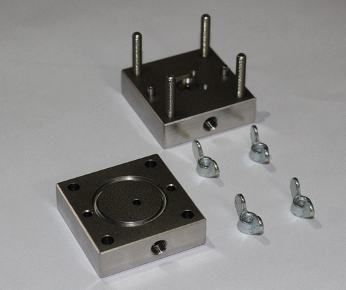
A specific sample holder has been machined for these high pressure tests. A picture is provided in Figure . Fittings from Upchuch Scientific are used to connect the sample holder to the fluidic line. The tightness is secured by two orings in MQV, shore 50. Overall sample holder dimensions are 40 mm x 40 mm x 24 mm. Since the pressure is applied onto the top of the chip (silicon membrane side), the sample holder has a flat reference surface with only one outlet hole on the glass wafer side to prevent any bending or breakage of the chip. The fluidic resistance of the sample holder itself is more than 3 orders of magnitude smaller that the chip itself.
5.3. Test preparation
Fluids of 12 and 24 cP are obtained by mixing pure deionized water filtered at 0.2 μm and glycerol (99.5% from Reactolab, density 1.26) at 20°C. Mixture preparation procedure: an initial mass of glycerol is measured using the scale Sartorius MC1 620, and the mass of water needed to get the right viscosity is calculated and mixed with the glycerol using a magnetic stirrer. Typical mixtures used during the tests are described in Table , including an estimation of the final density.
Table 5. Description of the measured mass fractions for 12 and 24 cP water/glycerol mixtures
The flowmeter, which is originally calibrated for water and ethanol, has been calibrated using the scale for 12 and 24 cP respectively. A corrective factor has been derived to obtain the exact flowrate in μL/s. A systematic check of this corrective factor is made for each test using the scale and the estimated density of the mixture. This test with the scale is made at the highest flowrate to minimize measurement errors. The viscosity of the mixtures has been estimated experimentally using a reference PEEK capillary tubing (length 126 mm, ID = 0.4 mm). The flow rate through this tubing has been measured at 20°C using iteratively water and the different mixtures. Test pressure has been varied so as to reach the typical regulation flow rate of the devices. The applied pressure versus flow rate characteristic is fitted linearly to determine the fluidic resistance of the tubing for each fluid. The ratio of the fluidic resistance obtained at nominally 12 cP and 24 cP against that obtained at 1 cP indicates the real viscosities:
| • | for 12 cP experimental mixture: Rf (12 cP) / Rf (1 cP) = 12.04 | ||||
| • | for 24 cP experimental mixture: Rf (24 cP) / Rf (1 cP) = 23.71 | ||||
The characterization of the different elements of the fluidic line has been made using a similar protocol using the flowmeter:
| • | all fluidic restrictions of the fluidic line are removed except the element to be tested. | ||||
| • | the reservoir pressure is gradually increased in order to get 6 different flow rates from 0 to 2 mL/min. | ||||
| • | the pressure versus flowrate characteristic ∆(Q) is fitted linearly to derive the fluidic resistance using the formula ΔP = Rf × Q. | ||||
The results obtained using pure water are provided in Table .
Table 6. Measured fluidic resistances with pure water of the main elements of the fluidic line
5.4. Test method
The tests have been performed in a class ISO 7 cleanroom with temperature regulation at 20 ± 2°C. Three samples per design are tested. The test method proposed here is valid for both mixtures (12 and 24 cP):
| • | Pressure sweep from 0 to 20 bar using step of 1 bar at low pressure (<7 bar) and steps of 2 bar at higher pressure. | ||||
| • | Measurement of the flowrate with the flowmeter Sensirion*. | ||||
| • | Final visual inspection. | ||||
*The fluid is infused into a beaker placed on the Sartorius scale for an additional measurement of the flowrate (at least 2 verifications per test). The weight in g measured during 1 minute is converted in mL/min using the estimated density of the fluid (see Table ).
6. Results
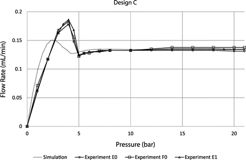
Experimental flow rate versus applied pressure characteristics for 3 different devices of design A, B and C are provided in Figures – respectively. At low pressure, all curves exhibit a linear regime with a slope that depends on the fluidic resistances of the fluidic line and the diffusers themselves. The flow rate reaches a maximum value before decreasing and showing a sudden change of slope at the contact between the membrane and the substrate at about 4, 5 and 7 bar for the designs A, B and C respectively. At higher pressure, the flow rate is basically constant for every design in the range 7–21 bar, as expected. Based on the metrology data provided in paragraph §4, theoretical curves are also shown for the sake of comparison. It is important to note that the model does not take into account the additional fluidic resistances of the fluidic line, which result in a shift of the whole fluidic characteristics towards high pressure. Setup limitations do not allow testing at higher pressures but flow regulation up to 35 bar is theoretically expected. This pressure corresponds to the maximum pressure that such a membrane can sustain. This limit has been evaluated on three different chips by applying pneumatic pressure directly on the chip (by shunting the pressure controller that is limited to 21 bar). This experimental burst pressure matches theoretical expectation corresponding, in FEM simulations, to a maximum stress of 0.8 GPa on the membrane edges. The flatness of the fluidic characteristics confirms the pertinence of the membrane deformation modelling despite its highly non-linear behavior. The flow rate, for the design A tested at 12 cP, is slightly larger than expected (about 15%) while designs B and C tested at 24 cP are in the pressure range of interest neatly aligned with the flow rate targets, within the range of measurement accuracy (approximately 5%). An important result is the low dispersion of the fluidic characteristics despite the measurement errors: it could be attributed to the robustness of the design because the machining tolerances have been considered in the genetic algorithm to select the best candidates.
Figure 10. Theoretical fluidic characteristic for design A at 12 cP compared to experimental data obtained using 3 different samples F6, H4 and G5.
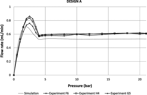
Figure 11. Theoretical fluidic characteristic for design B at 24 cP compared to experimental data obtained using 3 different samples C7, D7 and A4.
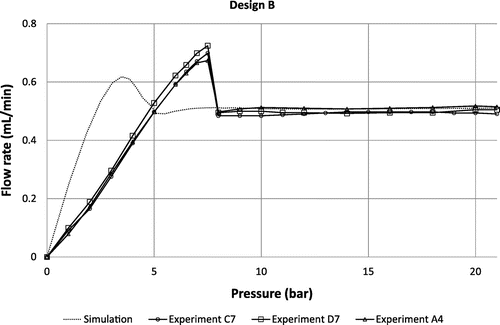
Figure 12. Theoretical fluidic characteristic for design C at 24 cP compared to experimental data obtained using 3 different samples E0, F0 and E1.
These experimental data show that silicon microfluidic valves comprising flexible membranes having through holes are suitable for the passive flow regulation of viscous fluids (24 cP) in the range 7–21 bar. It has been confirmed that the utilization of a genetic algorithm is especially useful in order to conceive sturdier valve designs with respect to machining tolerances. Finally, the good match between simulations and experimental data suggests that the modelling is suitable to design more exotic fluidic profiles.
7. Conclusion
The design of passive flow regulators dedicated to infusion of viscous fluids has been optimized using a genetic algorithm. Machining and alignment tolerances for estimating the fitness function have been considered. Prototypes have been micromachined and characterized experimentally using 12 and 24 cP fluids. It has been demonstrated experimentally that this technology is suitable to passively infuse, with very high accuracy, viscous drug formulations (hyaluronic acid, adalimumab, golimumab …) at flow rates up to 1 mL/min independently from reservoir pressure variations that can reach 20 bar or more. The numerical modelling of the fluid dynamics has been adapted to account for the specific geometry of the valves in order to fit correctly the experimental data. The genetic algorithm arises as a powerful tool for fast and reliable microfluidic chip design optimization.
| Nomenclature | ||
| Rf | = | Fluidic resistance |
| ΔP | = | Pressure gradient between the inlet and the outlet of the valve |
| Q | = | Flow rate |
| u | = | Fluid velocity |
| η | = | Dynamic viscosity |
| = | Shear stress | |
| n, m | = | Empirical curve-fitting parameters |
| Rin | = | Hole radius |
| Rout | = | Pillar radius |
| h | = | Gap between the membrane and the pillar |
| ρ | = | Volumetric mass density |
| = | Off-axis parameters | |
| ε, ξ | = | Dimensionless parameters |
| θ | = | Polar coordinate angle |
| r | = | Radial coordinate |
| z | = | Vertical axis |
| ψ | = | Tilt angle |
| = | Generalized Reynolds number for power-law fluids | |
Funding
This work was funded by Debiotech S.A.
Acknowledgement
Authors wish to thank the staff of Center of MicroNanoTechnology at EPFL for support.
Additional information
Notes on contributors
E. Chappel
Eric Chappel was born in Chambéry (France) and works as R&D project manager at Debiotech S.A. He received a master degree in physics in 1996 (Université Grenoble Alpes) and accomplished his PhD thesis at French National High Magnetic Field Laboratory (Grenoble, 2000). His research interests are innovative medical devices, including insulin patch micropumps, hydrocephalus shunts, external ventricular drains, implantable pumps and on-body injectors.
References
- Au, A. K., Lai, H., Utela, B. R., & Folch, A. (2011). Microvalves and micropumps for BioMEMS. Micromachines, 2(2), 179–220. doi:10.3390/mi2020179
- Bird, R. B., Stewart, W. E., & Lightfoot, E. N. (2007). Transport phenomena (2nd ed.). New York, NY: Wiley. ISBN 978-0-470-11539-8.
- Chappel, E., Dumont-Fillon, D., & Mefti, S. (2014). Passive flow regulators for drug delivery and hydrocephalus treatment. In B. L. Gray & H. Becker (Eds.), Proceedings of SPIE Microfluidics, BioMEMS, San Francisco, CA. Medical Microsystems XII, 8976, 89760S1–89760S11). doi:10.1117/12.2036084
- Chhabra, R. P., & Richardson, J. F. (2008). Non-newtonian flow and applied rheology (2nd ed.). Oxford: Butterworth-Heinemann. ISBN 978-0-7506-8532-0.
- Dumont-Fillon, D., Hannebelle, M., van Lintel, H., & Chappel, E. (2016). Design of a passive flow regulator using a genetic algorithm. In I. Bársony, Z. Zolnai, & G. Battistig (Eds.), Proceedings of the 30th anniversary eurosensors conference – eurosensors 2016, 4–7 September 2016, Budapest. Procedia Engineering, 168, 1016–1019). doi:10.1016/j.proeng.2016.11.329
- Floreano, D., & Mattiussi, C. (2008). Bio-inspired artificial intelligence: Theories, methods and technologies. Cambridge, MA: MIT Press. ISBN 978-0-262-06271-8.
- Guyon, E., Hulin, J.-P., & Petit, L. (2001). Hydrodynamique physique (Nlle ed.). Paris, France: CNRS Editions. ISBN 2-271-05635-7.
- Madlener, K., Frey, B., & Ciezki, H. K. (2009). Generalized Reynolds number for non-newtonian fluids. Progress in Propulsion Physics, 1, 237–250. doi:10.1051/eucass/200901237
- Musard, H., Dumont-Fillon, D., van Lintel, H., & Chappel, E. (2018). Experimental characterization and modelling of microfluidic radial diffusers to be published.
- Na, T. Y., & Hansen, A. G. (1967). Radial flow of viscous non-Newtonian fluids between disks. International Journal of Non-Linear Mechanics, 2(3), 261–273. doi:10.1016/0020-7462(67)90027-3
- Oh, K. W., & Ahn, C. H. (2006). A review of microvalves. Journal of Micromechanics and Microengineering, 16, R13–R39. doi:10.1088/0960-1317/16/5/R01
- Segur, J. B., & Oberstar, H. E. (1951). Viscosity of glycerol and its aqueous solutions. Industrial & Engineering Chemistry, 43(9), 2117–2120. doi:10.1021/ie50501a040
- White, F. M. (1991). Viscous fluid flow (2nd ed.). Boston, MA: McGraw-Hill. ISBN 0-07-069712-4.
- Zhang, X., Xiang, N., Tang, W., Huang, D., Wang, X., Yi, H., & Ni, Z. (2015). A passive flow regulator with low threshold pressure for high-throughput inertial isolation of microbeads. Lab on a Chip, 15, 3473–3480. doi:10.1039/C5LC00647C
Appendix A
We consider first that the valve opening h is small compared to Rin and Rout. We assume a steady, radial and laminar flow through the valve. According to the symmetry of the system described in Figure and the former hypothesis, we have:
(13)
(13)
where u is the flow velocity.
We write now the Navier-Stokes equation in the cylindrical coordinate system:
(14)
(14)
where η is the dynamic viscosity of the fluid and P the pressure in the incompressible fluid.
Ideal valve with Newtonian fluid
We assume that the tilt angle ψ between the membrane and the pillar is equal to zero. The integration of the term of Equation (2) leads to:
(15)
(15)
The integration of the 3rd part of Equation (14) gives, using the following boundary conditions: P = Pin for and P = Pout for
:
(16)
(16)
Finally we derive the expression of the flow rate Q by an additional integration:
(17)
(17)
Valve tilted by a single rigid particle
A tilted valve is typically a normally closed valve which has trapped a single rigid particle of diameter h0 onto its valve seat. Because it results in a permanent opening of the valve, it is interesting to have an estimation of the leakage induced by such defects. We suppose that the width of the valve seat Rout − Rin is small compared to Rin and Rout.
The Equation (15) then becomes:
(18)
(18)
where
(19)
(19)
Finally we obtain the expression of the flow rate Q:
(20)
(20)
We deduce that the flow rate, for a valve showing a homogeneous opening of h, is 3.2 times higher than the same tilted valve having trapped a single rigid particle of diameter h onto its valve seat.
General case
We consider now the general case according to Figure , wherein the membrane exhibits a constant tilt angle ψ but not in contact with the valve seat. This case corresponds typically to the passive valves described in (Chappel et al., Citation2014), in particular in the high pressure regime where the distortion of the membrane is large. The expression (Equation19(19)
(19) ) becomes:
(21)
(21)
The expression of the flow rate through the valve is therefore:
(22)
(22)
Analytical solutions for laminar flow of non-newtonian fluids
It is well known that protein solutions submitted to high shear, for instance during a bolus injection, exhibit a non-Newtonian behavior. This behavior is usually due to the stretching, orientation or deformation of the proteins in the direction of the flow, so the viscosity is a function of the shear rate. We focus here on steady laminar flows and time-independent fluid behavior.
Power law fluid
We consider power law or Ostwald de Waele fluid (Chhabra & Richardson, Citation2008), wherein the relationship between the shear stress σ and the shear rate can be approximated by:
(23)
(23)
See also Equation (1) for the expression in term of apparent viscosity.
Shear-thinning behavior fluids are characterized by while newtonian fluid corresponds to n = 1. The expressions of the flow rate through circular conduits or between two infinite parallel plates can be found in many fluid rheology textbooks, e.g. (Chhabra & Richardson, Citation2008). We derive here the expression for the annular valve described previously (with cylindrical symmetry, see (Na & Hansen, Citation1967) for the derivation of the general formula using the Sisko’s model).
We write the conservation of the momentum of an annular fluid element comprised between r and r + dr at ± z. The top side of the valve seat is located at the coordinate while the bottom side of the membrane is located at
. We assume that the change of the shear stress along r is small. According to the valve geometry, we have:
(24)
(24)
We get:
(25)
(25)
Or, after simplification:
(26)
(26)
Using the symmetry of the system we only solve the Equation (26) in the mid-plane . Since
is negative in this region, the shear stress for a power-law fluid is given by:
(27)
(27)
Combining Equations (26), (27) and integrating with respect to z yields for the velocity distribution:
(28)
(28)
To satisfy the no-slip condition at the walls, we have ur = 0 at . Therefore:
(29)
(29)
To derive the expression of the flow rate, the pressure profile as a function of r shall be determined using the flow continuity equation:
(30)
(30)
Or
(31)
(31)
We get:
(32)
(32)
Using the boundary conditions defined previously, the fluid pressure P in the region and Rin < r < Rout is:
(33)
(33)
We derive:
(34)
(34)
The volumetric flow rate Q of liquid is obtained by integrating the velocity over a cross section of the valve:
(35)
(35)
Combining (29), (34) and solving (35) yields:
(36)
(36)
We obtain:
(37)
(37)
Finally, the volumetric flow rate of power-law fluid in an annular valve can be expressed by:
(38)
(38)
Application to passive flow control valve design
The fluidic pathway of passive flow control valves as described in (Chappel et al., Citation2014) exhibits channels of circular cross-section and other types of flow restrictions.
The flow rate of power-law fluid in such cylindrical channel is, according to (Chhabra & Richardson, Citation2008):
(39)
(39)
where R is the channel radius. It can also be written in the following form:
(40)
(40)
where the term is not a function of the pressure:
(41)
(41)
The pressure drop induced by the viscosity in the whole device, considering several fluidic pathway i, is therefore:
(42)
(42)
where j represents the different flow restrictions in each pathway i.
We introduce also singular head losses for the element j of each pathway i:
(43)
(43)
These losses are due to, for instance, sudden changes of channel section.
The total pressure drop through the device is therefore:
(44)
(44)
Since this equation has no general analytical solution for any n ≠ 1, numerical computations are used to estimate the terms Qi by iterative method.

