 ?Mathematical formulae have been encoded as MathML and are displayed in this HTML version using MathJax in order to improve their display. Uncheck the box to turn MathJax off. This feature requires Javascript. Click on a formula to zoom.
Abstract
Reliable quantification of joint flexibility of non-ductile RC frames is critical for seismic vulnerability assessment. The issue of super-element joint models causing numerical divergence in non-linear time history analysis of reinforced concrete frames is investigated. The rigid joint assumption and a single rotational spring model are implemented for comparison. Reinforced concrete subassemblies and a one-third scaled frame have been employed for validation. Probabilistic seismic demand analysis indicates that super-element joint model may be less vulnerable relative to the single-component joint model. Furthermore, the shift in fragility function may lie in between the rigid joint and single-component joint modeling schemes, implying non-divergence.
Public Interest Statement
Earthquake reconnaissance surveys have stressed that non-ductile detailing of RC joints should not be tolerated, particularly in highly seismic regions. Nonetheless, in low-moderate regions, several existing RC buildings have been designed ignoring the relevant role which joints play during seismic action. Hence, when performing seismic vulnerability studies of building in these regions, there is a need to incorporate the contribution of joint flexibility in order to produce reliable predictions. Even though several numerical approaches for quantifying joint flexibility has been proposed in literature, they may render different predictions since the mathematical concepts and assumptions employed in developing these analytical joint model schemes vary. The study therefore sought to investigate and demonstrate the inherent variations of two explicit joint models. Findings of this research stresses the importance of including joint flexibility, as well as recommending practical and efficient modelling strategies in performing risk and vulnerability assessment of non-ductile RC frames.
1. Introduction
Existing earthquake reconnaissance surveys (Moehle & Mahin, Citation1991; Sezen et al., Citation2000) have stressed that non-ductile detailing of structural components should not be tolerated in highly seismic zones. Therefore, in performing vulnerability assessment of existing older-type reinforced concrete structures, the importance of joint flexibility, and its impact on seismic performance must be considered. This is because such joints are unable to dissipate larger amount of hysteretic energy, as result of limited shear capacity. They may therefore fail when subjected to high shearing stress from earthquake-induced forces. As noted by Moehle and Mahin (Citation1991), failure within the joint panel of reinforced concrete structures may be a significant contributor to the global collapse of the system. Hence researchers (Celik & Ellingwood, Citation2008; Jeon, Citation2013; Park & Mosalam, Citation2012) have proposed joint shear strength models that can be used to predict their behavior under seismic excitation. Most of these models have been validated and calibrated to satisfy specific RC joint configurations and types, by employing various approaches to the model development. Nonetheless, reliable quantification of the seismic performance of existing reinforced concrete buildings has been one of the major challenges within the earthquake engineering research community. Intuitively, by quantifying joint contribution in the mathematical formulation of a structural system, particularly reinforced-concrete structures, one is able to reduce the epistemic uncertainties inherent in the probabilistic risk assessment process.
In order to incorporate joint flexibility in nonlinear seismic analysis, most researches have quantified the deformations due to shear and pullout failures. By proposing and defining joint shear constitutive models, including bond strength-slip models, successful incorporation of joint flexibility into computer simulations are now carried out through various idealizations of the joint panel zone (rotational springs, bar-slip springs and link elements) (Birely, Lowes, & Lehman, Citation2012; Borghini, Gusella, & Vignoli, Citation2016; Hassan, Citation2011; Jeon, Citation2013; Long & Lee, Citation2015; Shafaei, Zareian, Hosseini, & Marefat, Citation2014). One major simplification has been to explicitly model the joint response by providing a single rotational spring to simulate all the underlining inelastic mechanisms. An extension of this approach is to introduce rigid links that span the joint dimensions, and this has been arguably the most widely used approach to numerically simulate and quantify joint flexibility (Celik, Citation2007; Hassan, Citation2011; Theiss, Citation2005). Nonetheless, concerns such as its being inappropriate at capturing joint kinematics, has hindered its usage in some research works.
In view of this, super-element joint models which may allow for transparency in assessing the individual contributions of major inelastic mechanisms have been proposed by some researchers for accurate simulation of joint kinematics (Lowes & Altoontash, Citation2003; Ning, Yu, & Li, Citation2016; Youssef & Ghobarah, Citation2001; Zhang, Hou, & Ou, Citation2016). Even though this approach has been extensively validated by experimental responses of quasi-statically tested RC sub-assemblies, a couple of researchers have noted that their usage may cause numerical divergence, when performing non-linear time history analysis (Park & Mosalam, Citation2012). Mitra and Lowes (Citation2007) noted that this numerical instability in the global solution algorithm may be attributed to the strain softening behavior of bar-slip springs, which forms part of the composition of the super-element models. Significant modification has been made to the parent model to address this issue, with subsequent verification and validation using an extensive dataset of quasi-statically loaded sub-assemblages. A major drawback to its usage has been the relatively larger number of one-dimensional constitutive models which tends to make it computationally demanding as opposed to the single-element joint model, that requires a single constitutive model. Therefore, studies adopting the use of the super-element joint models for quantifying joint flexibility in nonlinear simulation of RC frames have been given little attention.
This study seeks to explore the relative contributions of joint flexibility in the estimation of the inelastic seismic response of gravity loading RC frames, when the single and super element joint modeling schemes are implemented in computer simulations. The explicit joint models of Lowes and Altoontash (Citation2003), referred to as super-element joint model, as well as that of Alath and Kunnath (Citation1995), referred to as scissors or single-joint model are adopted because of them being widely used by researchers and practitioners, and also their ease of implementation in the selected nonlinear analysis platform, OpenSees. Analytical models of three experimentally tested quasi-static sub-assemblages and a 1/3 scaled RC frame, which incorporated these two explicit joint models were used to verify and ascertain how realistic predictions can be obtained. The relevant exclusion of joint flexibility (rigid-joint) was investigated in order to demonstrate whether explicitly accounting for joint flexibility reduces the epistemic uncertainty and thus improves the reliability of the estimated seismic demands. Analytical fragility function which estimates the conditional probability of exceeding a specified limit state given an intensity of ground shaking, is finally used to assessing the inherent variations in the vulnerability assessment of a hypothetical RC frame for the aforementioned joint models.
2. Prediction of RC joint behavior under seismic loading
Strut and truss mechanisms are primarily the shear resisting mechanisms that ensure transfer of imposed seismic forces within the joint core, when RC frames as subjected to seismic forces. These mechanisms exhibit poor hysteretic properties and as such, as suggested by Paulay, Park, and Preistley (Citation1978), joint should not be seen as one of the major sources of energy dissipation, during seismic action. Nonetheless, in order for these mechanisms to be full mobilized, detailing requirements such as the presence of transverse hoops and anchoring of the beam longitudinal reinforcement in the joint core, is highly encouraged (Hassan, Citation2011). In all cases, should the shear capacity and bond strength be exceeded before yielding of longitudinal reinforcement of framing members during seismic action, joint failure may occur, thereby not allowing for the full utilization of the flexural capacities of these framing members. The joint may then serve as the weak link which can cause excessive drift responses in the global system. Le-Trung, Lee, Shin, and Lee (Citation2013) noted that the joint shear demand may be a much more significant metric for assessing the seismic performance of RC beam-column connections, rather than the limiting requirement of column-beam flexural capacity ratios as per current seismic code provisions. Hence quantification of the shear strength of joint in vulnerability assessment has been a major research front in recent times.
Notable design parameters that have been used to quantify the shear capacity of RC joints includes compressive strength of concrete, joint transverse reinforcement ratio, column axial load, joint aspect ratio, confinement factor and longitudinal reinforcement ratio. Researchers have assessed the shear capacities of RC joints by using either analytical or empirical methods. Strut and tie models (Meas, Li, & Imran, Citation2012) as well as average principal stress models were developed analytically to satisfy primarily equilibrium, constitutive and compatibility stress conditions within the joint core. These softening concrete models have been calibrated and verified using a limited experimental database of RC joint sub-assemblages, and as such are normally appropriate for a specific type of joint configuration such as unconfined exterior joints. For example, the softened strut and tie model proposed by Hwang and Lee (Citation2002), which satisfies three force transfer mechanisms, is appropriate for unconfined joints. As identified by Hassan (Citation2011) after the evaluation of this joint shear strength model, it was concluded that it may underestimate the concrete strut capacity of unreinforced exterior joints. This can attributed it to the fact that the compatibility equations were originally calibrated from RC panels, which may not be necessarily applicable to several RC joints types and configuration. Even though these analytical models can provide a fairly accurate prediction of the shear capacity of a specific class of joint typology, extension of their underline force transfer mechanisms to different types may seem inappropriate and may need explicit verification from experimental results of RC sub-assemblages.
In other approaches, empirically developed model using various design parameters, are employed for estimating joint shear strength (Jeon, Citation2013; Kim & LaFave, Citation2009). These empirical models have been calibrated using either classical statistically methods or approaches which assess the effect of individual parameters, independently, through a collection of database of quasi-statically loaded sub-assemblages. These unified predictive equations obtained from these empirical models, provides a relatively simple means of modeling the various types of joints in RC frame simulations as compared to analytical approaches. In most of these models, the effect of column axial load on joint shear capacity is excluded. This emanates from the fact that there are contrasting views from different researches regarding its true impact on joint shear strength. A typical example is the work of Beres, White, and Gergely (Citation1992) that noted an increase in column axial load does not cause a significant improvement in the shear strength. On the contrary, the work of Pantazopoulou and Bonacci (Citation1994) revealed a decrease in shear strength with increasing axial load. Nevertheless, recent studies have asserted that the impact of axial load can significantly influence the mode of failure (Masi, Santarsiero, Lignola, & Verderame, Citation2013), with others setting a maximum level of axial load that can be beneficial to joint response (Meas, Li, & Pham, Citation2014).
With reference to pullout failure, short embedment length of the beam’s bottom longitudinal reinforcement within the joint core, may cause reduced utilization of the flexural capacities of adjoining members of older-type non-seismically designed RC frames. Current seismic codes such as FEMA (Citation2000a) recommends that in such cases, yield strength of the reinforcing steel within the plastic hinge zone of the structural component be reduced by a factor approximately equal to the relative ratio of provided embedment length to required development length. Bar-slip springs are typically used to represent anchorage failure, where its properties are defined with an appropriate bond-slip model or calibrated to experimental results. Depending on the stress state of anchored reinforcing bars researches have either used piecewise constant bilinear or trilinear bond strength model to estimate the resulting slip (Hassan, Citation2011; Lowes & Altoontash, Citation2003; Park & Mosalam, Citation2012). These responses can then be easily converted into moments and rotations used in implementing the component joint response in the non-linear assessment of the seismic reliability of RC frames.
3. Analytical modeling of joint
Considering the various approaches which can be employed in incorporating joint response in RC frame simulation, this study primarily investigates the impact a single-joint element model and a finite area super-element model for accurate simulation of the complex inelastic mechanisms of RC joints.
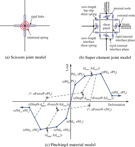
A constitutive model that account for both shear and bond-slip response was employed in developing the single-joint modelling scheme. The joint region is typically modeled by a single zero-length rotational spring with rigid offsets across the joint region to account for flexural rigidity. This joint modeling was first suggested by Alath and Kunnath (Citation1995), and has been extensively used to assess joint behavior under cyclic loading by a number of researchers (Celik & Ellingwood, Citation2008; Theiss, Citation2005). It requires the joint region to be connected by two nodes of length zero, each independently connecting the rigid links of adjoining beams and columns, respectively. The two translation degrees of freedom for each node are then being slaved by the other duplicate node, thereby allowing for only relative rotation between framing beam and column line elements. A one dimensional shear stress-strain response envelope is then required to describe the joint behavior under seismic loading. In this study, the unified predictive equation proposed by Jeon (Citation2013) for non-ductile RC joints, is employed in simulating the joint response. Figure (a) shows the schematic representation of this joint model.
As mentioned previously, one notable disadvantage in the implementation of this joint model is its inability to capture joint kinematics. For instance, by the constraining of the translation degrees of freedom to deform equally, the relative horizontal deformation between the upper and lower column elements becomes absent, which realistically may not hold. Hence a joint modeling scheme that possesses transparency in characterizing each individual mechanism may seem rather appropriate for capturing joint kinematics, considering its formulation.
Lowes and Altoontash (Citation2003) proposed a super-element model that consists of thirteen zero-length springs each defined by a one-dimensional constitutive model to simulate three major inelastic mechanisms (Figure (b)). The parent model consisted of eight bar-slip springs located at the perimeter of the joint. Mitra and Lowes (Citation2007) suggested that moving them to the centroid of compression and tension zones of beam and column, could yield better predictions of joint response. The bar-slip springs enables the quantification of strength and stiffness loss due to pullout of adjoining beam and column longitudinal reinforcement. In order to simulate shear-failure mechanism, a central shear panel zone connected by four internal nodes is properly calibrated to account for the relative rotation of framing members. Also, interface shear springs that are located at the perimeter of the joint panel zone is used to simulate shear flexibility and loss of shear strength at transfer of seismic forces due to opening of diagonal cracks during the loading history. By utilizing this two dimensional thirteen-component super-element joint modeling scheme, we can independently quantify the impact of the major inelastic mechanisms, as well as appropriately capture joint kinematics; a limitation of single-component joint modeling approach.
OpenSees (McKenna, Scott, & Fenves, Citation2010), a nonlinear finite element platform, allows the effective implementation of these two explicit joint models. This program was selected because it possesses a wide range of material models that can be used to simulate cyclic strength and stiffness deterioration of RC members. It also allows for the ease of integration of the joint model formulation with global solution algorithms for nonlinear seismic response assessment. To account for in-cyclic strength and stiffness degradation, the Pinching4 material model (Figure (c)) which employs a quad-linear monotonic backbone curve, coupled with a tri-linear unload-reload path controlled by the three damage rules for cyclic response, is adopted.
4. Joint model validation
Three experimental tested RC sub-assemblages, thus interior (Bracci, Reinhorn, & Mander, Citation1995), exterior (Pantelides, Hansen, Nadauld, & Reaveley, Citation2002) and knee (Pampanin, Calvi, & Moratti, Citation2002) RC joints under quasi-static loading have been selected and used in assessing the appropriateness of the aforementioned joint models. Typical model parameters for these joint model schemes in the selected sub-assemblages are given in Tables and . Further relevant input and analytical equations can be found in Adom-Asamoah and Osei (Citation2016, Citation2017). In all cases, the implicit assumption of joints being rigid is performed and compared to the two explicit joint modeling schemes.
Table 1. Load-deformation parameters for selected RC sub-assemblages
Table 2. Pinching4 constitutive model parameters
4.1. Interior joint
4.1.1. Brief description
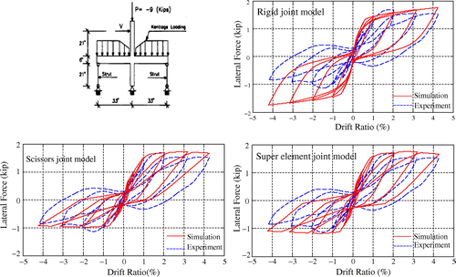
Aycardi, Mander, and Reinhorn (Citation1994), in predicting the nonlinear behavior of a 1/3 scaled gravity loading designed RC frame, initially assessed the behavior of structural components, i.e. columns and RC sub-assemblages, by subjecting them to quasi-static reverse cyclic loading at increasing drift amplitudes of ±0.25, ±0.50, ±0.75, ±1.00, ±2.00, ±3.00, ±4.00 and ±5.00 percent. Typical substandard reinforcing details identified and assessed were lap splices located at potential plastic hinge zones, inadequate joint transverse reinforcement and discontinuous bottom beam reinforcement in the joint. The interior joint sub-assemblage that exhibited a strong column-weak beam failure mechanism is selected in validating the modeling approach for both single-element and super element model.
4.1.2. Results
Figure shows the simulated base shear-drift responses for the three joint models under study. Both explicit models (single and super-element joint models) and rigid joint model were appropriate in capturing the pinching effect resulting from accelerated stiffness deterioration during unloading.
However, the implicit rigid-joint model showed symmetric load-deformation behavior in both loading directions, as opposed to the experimental observation, which showed a reduced shear capacity due to anchorage failure in one of the loading directions. This resulted in a much larger energy dissipation capacity which deviated from observed experimental responses. Hence the observation suggests and provides enough evidence as to the importance of including joint flexibility when quantifying seismic performance in vulnerability studies of non-ductile RC frames. Even though the explicit joint model were able to account for the effect of anchorage failure, the scissors joint model, herein representing the single-joint model, showed a much lower dissipation capacity as compared to the super-element model.
4.2. Exterior joint
4.2.1. Brief description
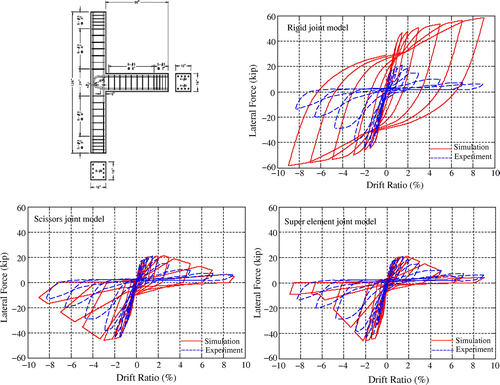
Pantelides et al. (Citation2002) assessed the impact of column axial load and joint embedment length in exterior joints with substandard details. In evaluating the seismic performance of such joint details, the longitudinal reinforcement was increased, so that a shear failure mode can be exhibited in order to quantify the seismic performance of shear-dominated exterior joints. Two levels of axial compressive loads (10 and 25%) as well as three different embedment length of bottom beam longitudinal reinforcement in the joints were investigated. The experimental validation of test unit 1, which was reported to have an axial compressive load of 10% with a 6 inches embedment length of bottom bars, is selected for the verification and validation of the joint modelling schemes understudy.
4.2.2. Results
The simulation of the base shear-drift responses of the exterior joint under the assumption of fully fixed end connections (rigid-joint model), showed a very large deviation from experimental responses in terms of ultimate shear strength, post peak shear strength envelope and cyclic degradation in strength and stiffness (see Figure ).
Also, the predicted amount of hysteretic energy dissipated in rigid joint model, was significantly above the experimental responses that possessed highly pinched hysteretic cyclic loops. This trend in load-deformation behavior of RC joint under quasi-static loading emphasizes and affirms the need for incorporating joint flexibility in computer simulation of RC frames with expected shear dominant joint failure modes. For the explicit joint models under study, the employed constitutive joint shear strength model, monotonic backbone curve and component degradation model, were adequate at giving an appropriate representation of observed responses. However, there were marginal difference in predicting the initial stiffness, strength and stiffness degradation and cyclic hysteretic paths at loading and unloading. The scissors joint model (single-joint model) underestimates the accelerated loss of lateral resistance upon reaching the peak shear capacity as compared to the super-element joint model which was in good agreement with the experimental results (see Figure ). This resulted in the scissors model having a higher unloading stiffness at larger drift amplitudes, and thus leading to a much larger energy dissipation capacity. Lastly, the observed pinching effect of the tested sub-assemblage, was appropriately captured in the super-element joint model than the scissors model. Generally, the super-element joint model provided a reliable simulation of responses that were in better agreement with experimental results than the scissors joint model. It can also be recognized that the reduction in epistemic uncertainty by explicitly accounting for joint flexibility is greater for the exterior joint than interior joint. Hence, it is worth noting that the geometric and material characteristics of a particular model may influence the extent of obtaining reliable non-linear predictions, since the exterior beam-column joint considered was a large-scale test specimen, compared to the interior case.
4.3. Knee joint
4.3.1. Brief description
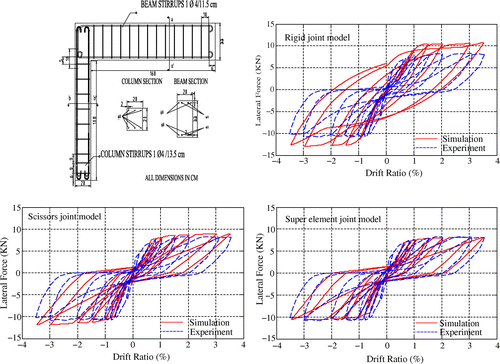
Pampanin et al. (Citation2002) in assessing the vulnerability of RC beam-column joints tested six 2/3 scaled beam-column joint sub-assemblages which had smoothed reinforcing bars and lack of joint transverse reinforcement. The designs of the specimens were based on allowable stress philosophy, and as such emphasis for ductile behavior at both local and global levels, was absent. The exterior knee joint typology from this investigation is selected in validating the aforementioned joint modelling scheme.
4.3.2. Results
Figure shows the simulated load-drift relationship of this RC knee joint for the various joint modelling schemes.
The reported failure mechanism was primarily controlled by flexural, concentrating at the column interface and bar pull-out that resulted in the pinching behavior of lateral force–drift response. This signified a beam yielding preceding joint shear failure mode, hence, even though it was expected that the rigid-joint model may overestimate the shear capacity, the discrepancy wasn’t that significant as in the case of the simulated responses of exterior joint of Pantelides et al. (Citation2002), previously discussed in Section 4.2.2. Both explicit joint models were adequate enough in characterizing the envelope of experimental responses in terms of shear capacity. However, they possessed a significantly reduced initial stiffness at loading and unloading, thereby reducing the expected amount of hysteretic energy that would have been dissipated from experimental load-deformation responses. Comparatively, the super-element joint model gave better predictions in terms of simulated backbone curves as well as cyclic responses.
5. RC frame validation
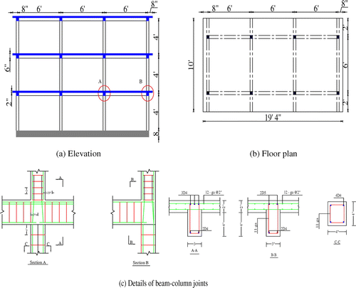
Bracci et al. (Citation1995) in evaluating the seismic adequacy of low-rise reinforced concrete buildings, tested a 1/3 scaled RC frame with non-seismic detailing provisions (Figure ). The roof displacement of the scaled model is selected in validating the joint modelling scheme.
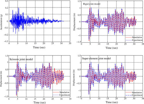
Figure illustrates how the various modelling schemes were able to match the roof displacement response history of this prototype frame that was subjected to the 1952 Taft N021E accelerogram with a peak ground acceleration of 0.2 g.
In all cases, the simulated responses closely matched the displacement history adequately. One physical reason for this observation may be attributed to the fact that it’s associated and tested interior sub-assemblages showed little joint shear distortion with beam yielding preceding shear failure. As seen in Figure , the super-element joint model gave the closest prediction for the observed maximum displacement, comparatively. In terms of peak displacement across the time history, the scissors or single-joint model governs.
6. Probabilistic seismic demand analysis of case study frames with various joint modeling schemes
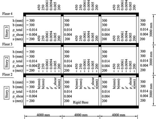
In order to quantify the degrees of modeling uncertainties from various joint modeling schemes, a nonlinear probabilistic seismic demand analysis (PSDA) of a similar hypothetical three story three bay RC frame with non-ductile detailing was performed in the finite element platform, OpenSees (Figure ).
A distributed plasticity line element, nonlinear beam Column element, was selected in modeling the beams and columns. Also, a fiber modeling approach which integrates the different stress-strain responses of the reinforcing steel, confined and unconfined concrete, was considered to allow for the spread of inelasticity along the length and across the section of the member. The constitutive behavior of the steel reinforcement was modeled with the uniaxial steel02 material object which employs a bilinear response envelope and Menegotto–Pinto (Citation1973) curves to describe the hysteretic response under cyclic loading as well as account for bauschinger effect. The concrete02 material object was adopted in modeling the concrete behavior, coupled with Mander’s stress–strain model for confined concrete.
In the seismic risk analysis framework, a suite of ground motions that are representative of a particular region or site is usually obtained from historical records or stochastically simulated approaches. The stochastic time-series earthquake model developed by Yamamoto (Citation2011) was employed. This model employs the wavelet packet transform to easily modulate the time and frequency characteristics of the ground motion. It has been validated for a wide range of magnitude, structure-specific modal periods, shear wave velocities, etc. A cumulative sample of 180 synthetic records were generated depending widely on the range of magnitudes, that is, 6 to 8, with a 30 m depth shear wave velocity of 400 cm/s. From this, a Latin hypercube experimental design that models the variation in the compressive strength of concrete, tensile yield strength of steel and damping ratio was constructed with each realization mapped to a random sample of the ground motion for nonlinear time history analysis. The statistical properties of these random variables are shown in Table . Popular estimations methods in literature that are usually employed to assess the seismic reliability of a structure includes cloud analysis (Jalayer, Citation2003), multiple stripe analysis (Baker & Cornell, Citation2006) and incremental dynamic analysis (Sengupta & Li, Citation2014). The conventional cloud analysis was selected because a closed form solution can be easily presented, to facilitate the computation of seismic fragility functions (Baker & Cornell, Citation2006). However, an underlining assumption of constant variance (homoscedascity) across the range of ground motion intensity may not hold when frames are excited beyond their linear-elastic regions. This stems from the fact that RC structures with deteriorating hysteretic behavior possesses an inherent strain softening phenomenon after reaching their ultimate capacities (Liel, Citation2008), which accelerates nonlinear behavior. Baker and Cornell (Citation2006) noted for seismic drift response above 10% and or with a first mode elastic spectral acceleration of 2.5, global dynamic instability is reached. Using these recommendations, the seismic responses from the non-linear time history analysis were processed to exclude such results in order to develop a well-defined closed form solution.
Table 3. Statistical properties of parameters for Latin-hyper cube experimental design
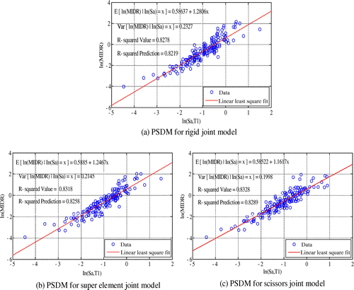
Adopting the terms of the Pacific Earthquake Engineering Research (PEER) Center, the scalar intensity measure (IM) used in computation of the seismic reliability was the 5% damped spectral acceleration at the first modal period of the building. The engineering demand parameter also adopted is the maximum inter-story drift ratio (MIDR) because it is closely related to the degree of damage sustained by structural components under earthquake excitation. An extensive research of the probability distribution of this parameter (MIDR) has been found to be lognormal, and this assumption has been implicitly used in performing the cloud analysis. Figure illustrates the relationship between the Sa(T1) and MIDR both in the log-transformed space for the various joint modeling schemes.
By comparing the mean function for the various joint models, which here represents the median drift response for a given intensity measure, the rigid joint model exhibited the highest degree of inelasticity. This can be inferred from the slope of obtained seismic demand models as indicated in Figure . A slope of unity, signifies a perfect linear relationship between the intensity measure and the drift response in the basic space; “the equal displacement rule” as noted by Veletsos and Newmark (Citation1975). The mean functions from the various cases, in combination with the estimated variance, can be used to establish the 16th, 50th and 84th percentile of the observed data at a particular intensity measure. Results revealed that the increase in MIDR when joint flexibility is incorporated is not directly proportional to the Sa(T1), and that this phenomenon may be valid for lower ranges of ground motion intensities. A typical example is the median MIDR at Sa(T1) of 0.5 g which yields 0.739, 0.759 and 0.803% MIDR for the rigid, super-element and scissors (single) joint modelling schemes respectively.
However, at Sa(T1) of 1.5 g, the estimates of the median MIDR are 3.021, 2.986 and 2.876% for rigid, super-element and scissors joint models. This observation is consistent with the work of Park and Mosalam (Citation2012) that quantified the variation in the rigid and scissors (single) joint model, concluding that the increase in the drift responses may drop at larger spectral acceleration, particularly for more flexible frames. This was confirmed from the fact that the MIDR distribution along the story height is seen to be greatest for the first and second floors for the models in which the joint flexibility was explicitly accounted for (soft-story mechanism).
7. Assessment of analytical fragility functions
The probability of exceeding a prescribed limit state is usually a metric that is employed in computing the seismic reliability of a structure. This is usually lumped into a fragility curve which requires a functional relationship between the structural response and its associated ground motion intensity. The predefined limit states which reflects the extent of damage sustained by a structural component locally or globally, are treated as deterministic values. For example, the immediate occupancy limit state with a threshold drift ratio of 1% from FEMA (Citation2000b). The HAZUS manual (FEMA, Citation2003), mainly developed from expert opinions have outlined four damage states that can be used in estimating seismic losses. The median drift response are 0.5, 0.8, 2, 5% corresponding to slight, moderate, extensive and complete limit state with a dispersion of 0.3 were adopted from previous studies. By employing the cloud seismic analysis demand model with variables assumed to be lognormal distributed, the limit state probability of exceedance can be computed as per Equation (1).(1)
(1)
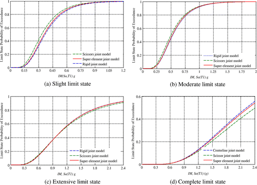
here C and D are the limit state capacity and seismic demand, S a is the spectral acceleration at the first mode, Φ is the cumulative Gaussian distribution function, a and b, are regression coefficients from regression analysis and β D|x, β C, β M represents the dispersion in the demand model, limit state capacity and modeling uncertainties (assumed to be 0.2). Following this procedure, Figure shows the generated analytical fragility functions for the hypothetical frame that incorporates the various joint modeling schemes at each damage state.
It is observed that for the slight and moderate limit states, the spectral acceleration corresponding to the 50% probability of exceedance (median capacity) is relatively lower for the explicit joint models as compared to the rigid joint model. This reflects the increased vulnerability inherent in incorporating joint flexibility in the assessment framework. Following from the discussion made above, the increase in MIDR when joint flexibility is incorporated is not directly proportional to the Sa(T1), as there is a significant vertical shift in the generated fragility curves at larger damage states. This was evident from the fact that, relatively lower intensity measures were adequate to reach these larger damage states. Hence, with the intuitive assumption that there will be an expected increase in the seismic vulnerability through increased fragility estimates when joint flexibility is incorporated, this may be valid for lower structural capacity limit states.
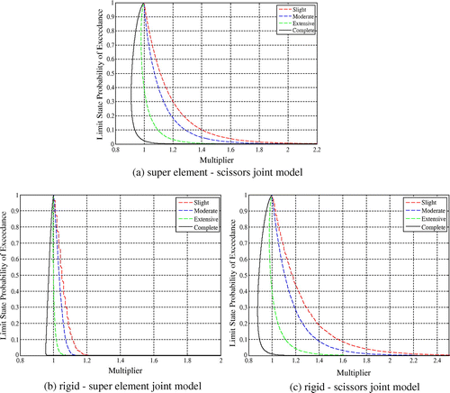
Figure illustrates the distribution of the shift in the vulnerability functions between the various modeling schemes for each limit state. It summarizes the extent to which there may be a significant increase in the limit state probability of exceedance by considering two joint modeling approaches at a time, using the concept of a scalar multiplier.
The scissors (single) joint model apparently gives the most vulnerable estimate of our knowledge of the extent of damage for a particular ground motion intensity, particularly for lower damage states, On the contrary, for complete limit state capacity, the response from the rigid joint model may be critical. It is worth noting that there are marginal differences among the generated analytical fragility function for the various damage states considered (see Figure ). Hence, given the numerical complications inherent in incorporating joint flexibility through the implementation of the super-element joint model in non-ductile RC frame, it will be practically convenient to model the joint panel zone of such frames as single-component (scissors model) at efficient computational time.
In relating the fragility functions for the super-element model to the scissors (single) joint model, a multiplier greater than unity is required for the slight and moderate limit states (see Figure (a)). This emphasizes the increased vulnerability for the scissors joint model at lower limit state capacities. However, for both extensive and complete limit state, the multiplier falls below unity, for intensity measures corresponding to above 40% probability of exceedance. This signifies an increased vulnerability for the frame that adopted the super-element joint model in accounting for joint flexibility. One implication of this phenomenon is that, in performing seismic collapse risk assessment, the simulation of joint region with multi-component deteriorating hysteretic models may increase the global flexibility, hence reducing the intensity measure required to cause collapse of the structural system compared to the popularly used single-component representation (zero–length rotational spring) joint behavior.
8. Summary and conclusions
This study sought to investigate the appropriateness of incorporating joint response in nonlinear time history analysis of RC non ductile frames where a multi-component spring model is employed. To this extent, the rigid joint and single-component joint models were also implemented, in order to quantify their variations in the estimated seismic demand for a given ground motion intensity. These analytical joint modeling schemes were verified under three typical joint configurations using experimental results of quasi-static reverse cyclic loading of interior, exterior and knee joints with no transverse reinforcement. Both explicit joint models (scissors and super-element) were fairly able to capture the observed horizontal shear strength of the chosen sub-assemblages, including the highly pinched behavior of beam-column joint subassemblies under load reversals. On the contrary, the estimated shear capacities of the rather implicit rigid joint model were much higher with a greater amount of hysteretic energy dissipated, as compared to experimental results. However, the roof displacement response history of a shake table test of a 1/3 scaled gravity loading design RC frame in which the three joint models were implemented, showed marginal difference in their peak values. A probabilistic seismic demand analysis was then performed to quantify the functional relationship between the ground motion intensity measure and the seismic response. With these functional relationships as input, analytical fragility functions for various joint modeling schemes are implemented, in order to ascertain the extent of seismic vulnerability. Result showed that the single-component joint model is the most vulnerable at lower limit state capacities with the rigid joint model being the least. However, this trend reverses at higher limit state, such as the complete limit state with a threshold of 5% median drift ratio. The super-element joint model yielded responses that were in between the two other joint models, but slightly skewed towards estimates for the rigid joint model. This trend emphasizes the appropriateness of implementing the super-element joint model during time history analysis of RC frames, without numerical divergence. Nonetheless, given the numerical complications inherent in implementing the super-element model for quantifying joint flexibility, it will be practically convenient to model the joint panel zone of such frames as single-component (scissors model) at efficient computational time. It is imperative to recognize these findings are valid for the particular hypothetical model considered, and hence no such generalization can be made. Therefore, further exploratory studies should be conducted for different structural systems and configurations.
Funding
The authors received no direct funding for this research.
Additional information
Notes on contributors
Mark Adom-Asamoah
Mark Adom-Asamoah obtained his PhD in Civil Engineering from Bristol University. He is a lecturer and the Provost of the College of Engineering, KNUST. His research revolves around performance-based earthquake engineering, reinforced concrete structures and several applications of finite element method in engineering.
Jack Banahene Osei
Jack Banahene Osei obtained his MPhil in Structural Engineering at the Kwame Nkrumah University of Science and Technology (KNUST). He is currently lecturing at the department of civil engineering at KNUST. His research revolves around performance-based earthquake engineering, reinforced concrete structures and several applications of finite element method in engineering.
References
- Adom-Asamoah, M. , & Osei, J. B. (2016). Nonlinear seismic analysis of a super 13-element reinforced concrete beam-column joint model. Earthquakes and Structures , 11 (5), 902–925.
- Adom-Asamoah, M. , & Osei, J. B. (2017). Inelastic dynamic behaviour of simply modeled explicit and implicit non-ductile RC beam-column joints. Jordan Journal of Civil Engineering , 11 (4), 646–658.
- Alath, S. , & Kunnath, S. K. (1995). Modeling inelastic shear deformation in RC beam-column joints (pp. 822–825). Presented at the Engineering Mechanics, ASCE. Retrieved from http://cedb.asce.org/CEDBsearch/record.jsp?dockey=0093535
- Aycardi, L. , Mander, J. B. , & Reinhorn, A. M. (1994). Seismic resistance of reinforced concrete frame structures designed only for gravity loads: Experimental performance of subassemblages. ACI Structural Journal , 91 (5), 552–563.
- Baker, J. W. , & Cornell, C. A. (2006). Vector-valued ground motion intensity measures for probabilistic seismic demand analysis (No. 08). University of California, Berkeley: Pacific Earthquake Engineering Center.
- Beres, A. , White, R. N. , & Gergely, P. (1992). Seismic performance of interior and exterior beam-to-column joints related to lightly reinforced concrete frame buildings . Ithaca: Cornell University. Retrieved from https://books.google.com/books/about/Seismic_Performance_of_Interior_and_Exte.html?id=y5huHQAACAAJ
- Birely, A. C. , Lowes, L. N. , & Lehman, D. E. (2012). A model for the practical nonlinear analysis of reinforced-concrete frames including joint flexibility. Engineering Structures , 34 , 455–465. doi:10.1016/j.engstruct.2011.09.003
- Borghini, A. , Gusella, F. , & Vignoli, A. (2016). Seismic vulnerability of existing R.C. buildings: A simplified numerical model to analyse the influence of the beam-column joints collapse. Engineering Structures , 121 , 19–29. doi:10.1016/j.engstruct.2016.04.045
- Bracci, J. , Reinhorn, A. , & Mander, J. B. (1995). Seismic resistance of reinforced concrete frame structures designed for gravity loads: Performance of structural system. ACI Structural Journal , 92 (5), 597–608.
- Celik, O. (2007). Probabilistic assessment of non-ductile reinforced concrete frames susceptible to Mid-America ground motions (PhD). Atlanta, GA : Georgia Institute of Technology.
- Celik, O. C. , & Ellingwood, B. R. (2008). Modeling beam-column joints in fragility assessment of gravity load designed reinforced concrete frames. Journal of Earthquake Engineering , 12 (3), 357–381. doi:10.1080/13632460701457215
- FEMA . (2000a). Pre standard and commentary for the seismic rehabilitation of buildings (No. 356). American Society of Civil Engineers for the Federal Emergency Management Agency.
- FEMA . (2000b). Recommended seismic design criteria for new steel moment-frame buildings (SAC Joint Venture, Federal Emergency Management Agency, No. 350). Washington DC.
- FEMA . (2003). HAZUS-MH MR4 technical manual . Washington, DC: Federal Emergency Management Agency.
- Hassan, W. M. (2011). Analytical and experimental assessment of seismic vulnerability of beam-column joints without transverse reinforcement in concrete buildings (PhD). Berkeley: University of California.
- Hwang, S.-J. , & Lee, H.-J. (2002). Strength prediction for discontinuity regions by softened strut-and-tie model. Journal of Structural Engineering , 128 (12), 1519–1526. doi:10.1061/(ASCE)0733-9445(2002)128:12(1519)
- Jalayer, F. (2003). Direct probabilistic seismic analysis: Implementing non-linear dynamic assessments (PhD) . CA : Stanford University.
- Jeon, J. (2013). Aftershock vulnerability assessment of damaged reinforced concrete buildings in California (PhD) . Atlanta, GA : Georgia Institute of Technology.
- Kim, J. , & LaFave, J. (2009). Joint shear behavior of reinforced concrete beam-column connections subjected to seismic lateral loading (No. NSEL-020). University of Illinois at Urbana-Champaign: Department of Civil and Environmental Engineering.
- Le-Trung, K. , Lee, K. , Shin, M. , & Lee, J. (2013). Seismic performance evaluation of RC beam-column connections in special and intermediate moment frames. Journal of Earthquake Engineering , 17 (2), 187–208. doi:10.1080/13632469.2012.730116
- Liel, A. (2008). Assessing the collapse risk of California’s existing reinforced concrete frame structures: Metrics for seismic safety decisions (PhD). CA : Stanford University.
- Long, X. , & Lee, C. K. (2015). Modelling of two dimensional reinforced concrete beam-column joints subjected to monotonic loading. Advances in Structural Engineering , 18 (9), 1461–1474. doi:10.1260/1369-4332.18.9.1461
- Lowes, L. N. , & Altoontash, A. (2003). Modeling reinforced-concrete beam-column joints subjected to cyclic loading. Journal of Structural Engineering , 129 (12), 1686–1697. doi:10.1061/(ASCE)0733-9445(2003)129:12(1686)
- Masi, A. , Santarsiero, G. , Lignola, G. P. , & Verderame, G. M. (2013). Study of the seismic behavior of external RC beam–column joints through experimental tests and numerical simulations. Engineering Structures , 52 , 207–219. doi:10.1016/j.engstruct.2013.02.023
- McKenna, F. , Scott, M. H. , & Fenves, G. L. (2010). Nonlinear finite-element analysis software architecture using object composition. Journal of Computing in Civil Engineering , 24 (1), 95–107. doi:10.1061/(ASCE)CP.1943-5487.0000002
- Meas, K. , Li, B. , & Imran, I. (2012). Seismic performance of lightly reinforced concrete exterior beam-column joints. Advances in Structural Engineering , 15 (10), 1765–1780. doi:10.1260/1369-4332.15.10.1765
- Meas, K. , Li, B. , & Pham, T. P. (2014). Experimental and numerical studies on the seismic performance of RC interior beam-column joints. Advances in Structural Engineering , 17 (2), 233–247. doi:10.1260/1369-4332.17.2.233
- Menegotto, M. , & Pinto, P. (1973). Method of analysis of cyclically loaded reinforced concrete plane frames including changes in geometry and inelastic behavior of elements under combined normal geometry and inelastic behavior of elements under combined normal force and bending. In Proceedings of the IABSE Symposium on the Resistance and Ultimate Deformability of Structures Acted on by Well-Defined Repeated Loads . Lisbon.
- Mitra, N. , & Lowes, L. N. (2007). Evaluation, calibration, and verification of a reinforced concrete beam-column joint model. Journal of Structural Engineering , 133 (1), 105–120. doi:10.1061/(ASCE)0733-9445(2007)133:1(105)
- Moehle, J. P. , & Mahin, S. A. (1991). Observations on the behavior of reinforced concrete buildings during earthquakes. Special Publication , 127 , 67–90. doi:10.14359/3007
- Ning, C.-L. , Yu, B. , & Li, B. (2016). Beam-column joint model for nonlinear analysis of non-seismically detailed reinforced concrete frame. Journal of Earthquake Engineering , 20 (3), 476–502. doi:10.1080/13632469.2015.1104759
- Pampanin, S. , Calvi, G. M. , & Moratti, M. (2002). Seismic behavior of R.C. beam-column joints designed for gravity only . Retrieved from https://ir.canterbury.ac.nz/handle/10092/173
- Pantazopoulou, S. J. , & Bonacci, J. F. (1994). On earthquake-resistant reinforced concrete frame connections. Canadian Journal of Civil Engineering , 21 (2), 307–328. doi:10.1139/l94-032
- Pantelides, C. , Hansen, J. , Nadauld, J. , & Reaveley, L. (2002). Assessment of reinforced concrete building exterior joints with substandard details (PEER Report No. 18). University of California, Berkeley: Pacific Earthquake Engineering Center.
- Park, S. , & Mosalam, K. (2012). Experimental and analytical studies on reinforced concrete buildings with seismically vulnerable beam column joints (PEER Report No. 03). University of California, Berkeley: Pacific Earthquake Engineering Center.
- Paulay, T. , Park, R. , & Preistley, M. J. N. (1978). Reinforced concrete beam-column joints under seismic actions. Journal Proceedings , 75 (11), 585–593. doi:10.14359/10971
- Sengupta, P. , & Li, B. (2014). Seismic fragility evaluation of lightly reinforced concrete beam-column joints. Journal of Earthquake Engineering , 18 (7), 1102–1128. doi:10.1080/13632469.2014.919890
- Sezen, H. , Elwood, K. , Whittaker, A. , Mosalam, K. , Wallace, J. , & Stanton, J. (2000). Structural engineering reconnaissance of the August 17, 1999 earthquake: Kocaeli (Izmit), Turkey (PEER Report No. 09). University of California, Berkeley: Pacific Earthquake Engineering Center.
- Shafaei, J. , Zareian, M. S. , Hosseini, A. , & Marefat, M. S. (2014). Effects of joint flexibility on lateral response of reinforced concrete frames. Engineering Structures , 81 , 412–431. doi:10.1016/j.engstruct.2014.09.046
- Theiss, A. (2005). Modeling the earthquake response of older reinforced concrete beam-column building joints (MSc). Seattle: University of Washington.
- Veletsos, A. S. , & Newmark, N. M. (1975). Effect of Inelastic Behavior on the Response of Simple Systems to Earthquake Motions (pp. 567–584). Presented at the Selected Papers By Nathan M. Newmark: Civil Engineering Classics, ASCE. Retrieved from http://cedb.asce.org/CEDBsearch/record.jsp?dockey=0282550
- Yamamoto, Y. (2011). Stochastic model for earthquake ground motion using wavelet packets (Ph.D. Dissertation). Department of Civil and Environmental Engineering, Stanford University (PhD). Stanford University, Department of Civil and Environmental Engineering.10.1201/b11332
- Youssef, M. , & Ghobarah, A. (2001). Modelling of RC beam-column joints and structural walls. Journal of Earthquake Engineering , 5 (1), 93–111. doi:10.1080/13632460109350387
- Zhang, P. , Hou, S. , & Ou, J. (2016). A beam–column joint element for analysis of reinforced concrete frame structures. Engineering Structures , 118 , 125–136. doi:10.1016/j.engstruct.2016.03.030

