Abstract
There are certain electrical power losses which have been affecting the availability of electrical power in developing countries. The rate of non-technical losses in developing countries is quite high which ranges from electricity theft and non-payment of bills. Therefore, this paper is aimed at the design and implementation of a Radio Frequency (RF) based wireless automatic energy meter reading system. This system uses a digital energy meter consisting of current and voltage sensors, analog to digital converters, a microcontroller and a Liquid Crystal Display (LCD) unit. The Base Station Wireless interfaced device was able to perform the desired interfacing function between the energy meter and the base station. Bills and reports were generated by the PC software and the outputs were found to be accurate. This system does not only reduce the cost of labour but also increases meter reading accuracy.
Public Interest Statement
The availability of electrical power in developing countries has been a critical issue. Therefore, the need to develop power system components that can help to minimize non-technical power losses in power system cannot be over-emphasized. This work is aimed at developing an RF based wireless automatic energy metering and billing system that can take care of over and under billings, and energy theft which have contributed large percent to non-technical power losses in Nigeria. This will be of great benefit to both the consumers and utility companies.
1. Introduction
Availability of constant electrical power is a key factor for the development of industries, people empowerment and nation’s development (Amaize, Airoboman, Adoghe, & Sanni, Citation2016; Oyedepo, Citation2012; 24X7 Power For All (Punjab), Citation2016). With the rapid increase in residential, commercial, industrial consumers of electricity in the world, it has become imperative for utilities companies to devise better techniques of gauging utilities’ consumption so that correct bills can be generated and invoiced (Ezennaya, Isaac, Okolie, & Ezeanyim, Citation2014; Orukpe & Agbontaen, Citation2013).
Energy meters are installed on customer’s premises and meter-readers go to these premises to collect information for their consumptions (Raghavendra, Ranganathan, Talwar, Wang, & Zhu, Citation2008). Most times the meters are installed inside people’s homes and if the consumer is not at home, the meter-reader cannot record the monthly consumption and then the utilities’ company has to resort to estimated billing method (Igbinovia & Orukpe, Citation2007). Hiring meter-readers by utilities’ companies and providing means of transportation to them is an expensive burden on the companies’ budgets. Some Customers consider meter-readers’ to their homes as an invasion of their privacy while some meters are usually by-passed by energy consumers which cause the company losses as they supply energy that is not being paid for by its consumers (Navani, Sharma, & Sapra, Citation2012).
In order to overcome these disadvantages of the meter reading system, efforts are underway around the world to automate meter reading and to provide comprehensive information to the consumer for efficient use of the utilities. It gives customers more information about their energy usage, receive timely and accurate billing (Palaniappan, Asokan, Bharathwaj, & Sujaudeen, Citation2015).
Therefore, to complement Automated Meter Reading (AMR) system initiatives underway in various countries, there is great need to implement a Wireless automatic energy meter reading system” (WAMRS) with a well simulated Software (Ighalo & Williams Citation2012) through a model of wireless electricity meter-reading system which is going to be very useful in Nigeria power system.
2. Literature survey
Cao, Tian, and Zhang (Citation2006) developed a wireless automatic energy-meter reading system using ZigBee technology. The wireless automatic energy-meter reading system presented here uses ZigBee networking to avoid difficulties and problems inherent to other meter reading techniques. In the above model either single parameter is used for developing AMR i.e. electricity and water or give general idea about designing of AMR. Designed model gives detailed design of AMR which will measure electricity and water and for each house and will forward recorded data to central station and will also send sms to user using gsm communication, with regard to due dates, bills and so on. Cao et al. (Citation2006) also developed ARM system which uses Bluetooth device for wireless data transmission for meter readings. Different Energy meters at different houses are connected with a number Radio frequency (Rf) nRf903 Bluetooth devices and Hyundai’s HY57V641620 SDRAM to run the operating system. These devices forward the data to a center hub, where all data are collected. As the Proposed system works well but the coverage ranges of an RF 903, its power consumption are still issues which can be changed with other appropriate solutions. Silviya, Vinodhini, and Salai Thillai Thilagam (Citation2014) proposed a model to remotely read electricity from energy meter readings through short message service (SMS) as done in (Matthews, Ajala, Atayero, & Popoola, Citation2017; Mousami, Vanjale, & KrunalPawale, Citation2014; Potnis, Chimnani, Chawla, & Hatekar, Citation2015; Supraja, Goutham, Subramanyam, Dasthagiraiah, & Prasad, Citation2014) for sending and receiving energy consumption but there is a problem of network issues at some time. Therefore, the need to develop a system that can take care of these problems cannot be over-emphasized.
3. Methodology
Details of the design of the RF based wireless automatic meter reading and billing system is given as the system can be divided into the following units: The wireless automatic energy meter (WAEM), the base station wireless interface device (BWID), and the PC based monitoring and billing software with database support.
3.1. The wireless automatic energy meter (WAEM)
The main function of the energy meter is to measure the current and voltage flowing in the power supply line in real time, deduce and store the value of the energy consumed by the consumer, display the energy consumed on its LCD display screen and transmit the measured data via radio to the central monitoring and billing station.
3.2. The ADC based energy meter
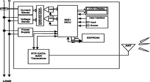
In this meter design, analog signal attenuation and shaping, conversion to digital format and multiplication are done by separate circuits. The block diagram of the circuit is shown in Figure .
3.3.1. ADC circuit design
This circuit was designed to receive analog current and voltage signal input and convert them to digital signals. The main component used in this design is the ADC0804.This component was chosen for this design in other to achieve
| • | Efficient and effective analog to digital signal conversion. | ||||
| • | Control over the output digital signals by a microcontroller. | ||||
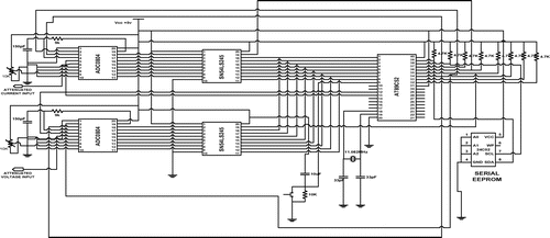
The ADCs are connected to a microcontroller via an interface IC called an octal bus driver. The IC used to provide this function is the SN54LS245. This octal bus transceiver is designed for asynchronous two-way communication between data buses. The circuit diagram of the analog to digital signal conversion is shown in Figure .
As illustrated in Figure , the attenuated and shaped current and voltage signals are connected to pin 6 (V+) of the ADCs. This is the analog signal input pin of the ADC. The current signal is connected to ADC1 while the voltage signal is connected to ADC2.
The read and write (pin 2 and 3) pins of the ADCs are connected to pins 34 and 35 of the microcontroller respectively. This enables the microcontroller to control the sampling of signals by the ADCs by sampling current and voltage signals at the same time. Pin 5 of the ADC is the interrupt pin. It tells the microcontroller that data has just been sampled.
Pin 5 of ADC1 and ADC2 is connected to the external interrupt pin 12 and 13 respectively of the microcontroller. The 8bit output of ADC1 and ADC2 is connected to the 8bit input of the BUFFER1 and BUFFER2 respectively. The output of these buffers is connected to port1 of the AT89S52 microcontroller (pin 1–8). The output of the buffers is controlled by the OE pin (pin 19). The OE pin of BUFFER1 is connected to pin 12 of the microcontroller while that of BUFFER2 is connected to pin 13 of the microcontroller. The buffers only produce output when a logic low is supplied to the OE pin.
3.3.2. Circuit diagram of the ADC based energy meter (Part One)
When electricity is supplied to the load, the power supply unit turns on the meter by supplying the required 10 V dc to the op-amps and 5 V to the other components of the meter. The current and voltage transformers help to convert current and voltage flowing to the load into current and voltage variable voltage signals respectively. The phase correction/signal shaping circuit attenuates the current and voltage signals into a form suitable for the ADCs. These convert the signals into digital data which are stored in the buffers (see Figure ).
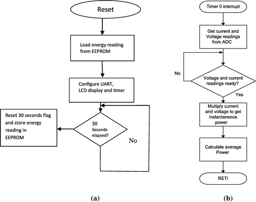
When power is supplied to the microcontroller performs the following procedures
| • | Places a logic high on pins 12 and 13 thus disabling the output of buffer1 and buffer2 | ||||
| • | Loads the previous energy values stored in the EEPROM in memory. | ||||
| • | Displays this initial value of energy on the LCD display. | ||||
| • | Starts its real time clock. | ||||
Every minute, the current value of the energy reading is stored in meter EEPROM so as to prevent data loss in the event of a power cut.
3.4. The communication protocol
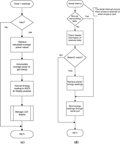
A simple call-and-response approach was used. Since both the energy meter and the base station were equipped with transceivers, this approach was easily implemented. If the base station gets some data, but it’s not complete, or appears garbled, a request for re-transmission is sent. The protocol is described succinctly as follows
| (1) | The receiver section of the energy meter, when not transmitting, listens for requests. | ||||
| (2) | When it gets one, the microcontroller program checks the header information if it is valid. | ||||
| (3) | The meter ID is extracted from the received data. | ||||
| (4) | A check is performed to see if the received meter ID is the same as that of the receiving meter. If they are different then step 1 is repeated | ||||
| (5) | If meter ID is the same, the transmitter section of the energy meter sends out the energy reading as packets | ||||
| (6) | The energy meter switches back to receive mode and step 1 is repeated | ||||
3.5. Operation principle of the RF based wireless automatic electrical energy metering and billing system
The general diagram of the RF Based Wireless Automatic Electrical Energy Metering and Billing System is shown in Figure .
Figure 6. Global view of the RF based wireless automatic electrical energy metering and billing system.
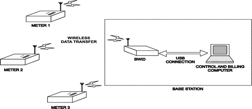
Each meter is connected to the home of a registered energy consumer. It measures the energy consumed continuously. At a time specified by the base station computer operator, the control and billing computer request for the energy readings of a specified meter. It embeds the meter ID in the instruction and sends it to the BWID (Base station Wireless Interface Device).
The BWID converts this instruction to wireless data and transmits it out to all the meters in its domain. All the meters receive the instruction. On reception of the instruction, each meter compares the meter ID embedded in the instruction with its own ID. If different, it ignores the instruction. If same, the meter responds by transmitting its present energy reading. All the devices including the BWID in this domain receive the transmitted data. The meters however ignore the transmission as they do not recognize it as an instruction.
On reception of the transmitted data, the BWID converts the data to computer readable format and sends it to the control computer via its USB connection. The control computer receives this data and checks for errors. If errors exist, it sends a data transmission request again to the specified meter until the data it received is correct and error free. If no errors exist, it stores the energy readings and updates the database of the consumer using the specified meter. If the received energy reading is below an average value specified by the operator, the control and billing software triggers an alert. This informs the operator of a possible bypass of the energy meter by the consumer. He can then dispatch a team to the location to investigate the matter.
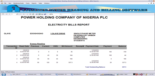
The control software is also capable of generating energy bills for each user.
3.6. Single meter monitoring and meter information
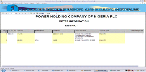
From the base station, a single meter can be selected by double clicking its icon. A separate window appears and displays instantaneous readings for the selected meter. Complete meter information is stored in the database and can be view or edited. The meter address, meter ID, owners name, last read date, last bill paid, current account, etc.
3.7 Bill, report generation and data base management
The PC software uses energy readings, and billing information like cost per KWh, fixed cost and VAT stored in the database to calculate the current bill. The task menu is from where commands can be issued for this function. To generate a bill click on the task menu then click on generate bill. Reports that can be generated by the PC software are monthly bill, current readings table, meter usage chart, meter information, district information, and customer statement of account. The PC software features forms that can be used to add, edit and remove records in the main data base. Four forms are provided as: Meter information, District information, Rates information and Transactions
3.8. Communication techniques and the control panel
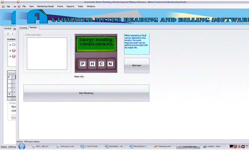
The software works with an RS-232 interface. The RS-232 standard serves as a link between a standard PC running the Billing software and the receiving unit in the base station. The first transition on TxD line is a signal to begin transmitting, and an idle condition for one character period is a signal to turn off the transmitter. The control panel displays the meters that are assigned to a district in a list. The middle section displays information of the meters and the last reading. Directly below the meters list is a large textbox that displays the raw data received from the meter. This is needed for troubleshooting. To read the meters manually, click on the “Read Meter Now” button. A record is added to the database reflecting the current reading in KWh; also the raw data is displayed in the control panel. For automatic meter reading, a read date and time can be set.
3.9. Implementing the microcontroller program
The microcontroller programs were implemented using the KeiluVision version 3. KeiluVisionis an integrated development environment (IDE) with software development tools for the 8051 microcontroller family. We present a discussion on how the microcontroller program for the wireless automatic meter reading and billing system was implemented using the μVision 3 package of Keil IDE on MS Windows platform
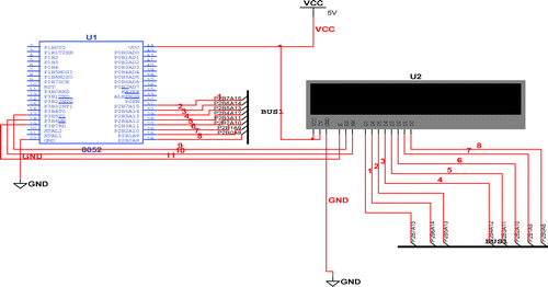
3.9.1. LCD code simulation
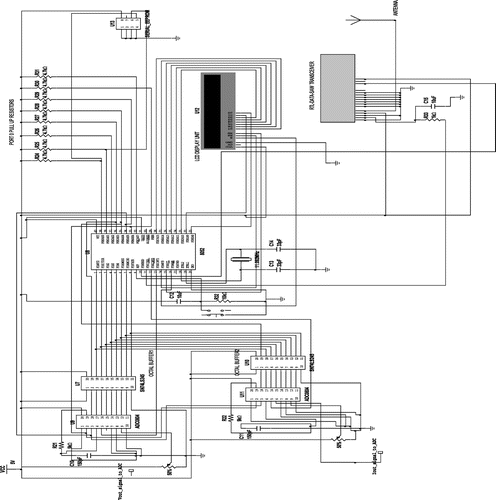
In this section we present the simulation setup for the LCD routines. The setup for this simulation is as shown in Figure .
3.9.2. ADC code simulation
A generic ADC provided in MULTISIM was used to simulate the behavior of the ADC used in this study. The code was modified in such a way that its behavior can be predicted from the simulation.
3.9.3. Power and energy calculation and meter calibration
A table of sample values for current and voltage readings was hardcoded. Power and energy consumed was calculated based on these values and the results sent to the LCD. Meter calibration is done in hardware; variable resistors are used to vary the voltage input to the ADC in such a way that when 220 V is measured, the ADC must have an output of 220 V. Similarly for current when 60Amps is measured, the ADC must have an output of 60Amps. Accumulation gives energy in watts-seconds. Further division by 3,600 yields Wh. To avoid this division, we pre-divide the inputs to the ADC by 60 each to get 220/60 or 3.66 V for the voltage ADC and similarly, for the current ADC 60/60 give 1 V. Thus 3.66 V (representing 220 V measured) at the input of the ADC is equivalent to 220 at the output of the ADC. Similarly 1 V (representing 60 A measured) at the input of the ADC is equivalent to 60 at the output of the ADC. Thus multiplying voltage and current in the program and accumulating every second gives energy directly in Wh.
4. Test and results
4.1. Calibration and testing of the ADC meter
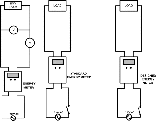
The meter was calibrated by connecting it to a fixed 1 KW (a pressing iron) load as shown in the circuit diagram in Figure .
The measured input supply voltage was 220 V AC while the measured current drawn by the load was 4.55 A as shown on the meters in Figure . A calibration program was written in the microcontroller strictly for this purpose. The program displays the measured current and voltage values on the LCD display.
The value of the measured current and voltage displayed on the LCD was compared with that displayed on the standard current and voltage meters connected in Figure . It was observed that the readings on the LCD display were slightly lower than the actual readings. Thus the variable resistors R1 and R2 are varied accordingly to make the values on the LCD display the same as the actual reading (see Table ).
Table 1. Test results of the ADC energy meter
4.2. Testing of the base station wireless interface device (BWID)
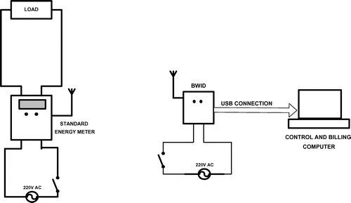
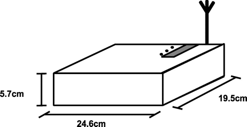
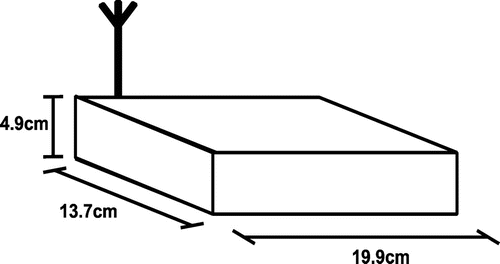
After construction, testing of the base station wireless interface device was carried out as shown in Figure .
The energy meter was connected to the power supply and a fixed load while the BWID was connected to power supply as shown in Figure . Its data output port was connected to the control computer via a USB connector cable. The control computer uses software that can manage a database of energy consumers, generate bills and manage data transaction. A REQUEST ENERGY READING instruction meant for the meter was sent by the control computer to the BWID.
4.3. Software testing
The first stage of software testing was simulation. The tool used for simulation of the 8051 program was National instruments’ Multisim version 10. Each segment of code that provides a related set of functions was simulated.
4.4. Result of the base-station wireless interface device (BWID) test
At a band rate of 1,200, the energy reading of the meter was displayed on the computer screen. Some data was received in error when the raw data was viewed however the software detected all errors. An accurate meter reading was achieved up to an approximate distance of 100 meters which can be increased from 100 m to any required distance with little adjustment.
4.5. Test results for the PC software
There were no run time errors in the program. The program executed as expected and all forms and reports were generated without errors. Several meter readings were taken and bills generated. The bills generated were found to be accurate.
4.6. Captured screens for PC software
Figures – are some captured screens from the PC software during the testing process.
5. Conclusion
The aim of this study which is to design a prototype RF based wireless automatic meter reading and billing system was achieved. The operation of the prototype was studied, from the results obtained, all the study’s objectives were achieved. The ADC based energy meter yielded the desired results with a relatively low percentage error of 4.85%. It receives and transmits data efficiently up to a distance of 100 m which can be increased from 100 m to any distance with little adjustment. The BWID was able to perform the desired interfacing function between the energy meter and the base station. Bills and reports were generated by the PC software and the outputs were found to be accurate. This device can be produced in large scale in Nigeria so as to take care of over and under billings and energy theft which have contributed large percent to non-technical power loss in Nigeria and this will be of great benefit to both the consumers and utility companies.
Additional information
Funding
Notes on contributors
Ukeh Orodje Edemirukaye
Ukeh Orodje Edemirukaye is a PhD Student in the Department of Computer Engineering, University of Benin, Benin City, Edo State. His research interest includes; Electrical Power System Reliability and Stability and Renewable Energy.
Aigboviosa Peter Amaize
Aigboviosa Peter Amaize is a PhD Candidate in the Department of Electrical and Information Engineering, Covenant University Ota, Ogun State. His research interest includes but not limited to: Power System Stability, Security, Reliability, Performance of Induction Machine and Renewable Energy.
Stanley Uzairue
Stanley Uzairue is a PhD student of information and communication engineering, Covenant University, Nigeria. His research interests are but not limited to; visible light communication, underwater communication, quality of service, fiber optics design and implementation, fiber to the home.
References
- Amaize, P. A. , Airoboman, A. E. , Adoghe, A. , & Sanni, T. F. (2016). A model for the mitigation of energy scarcity for a sustainable market in Africa. In International Conference on African Development Issues (CU-ICADI) (272–274), May 9–11, Ota.
- Cao, L. , Tian, J. , & Zhang, D. (2006). Networked remote meter-reading system based on wireless communication technology. In 2006 IEEE International Conference on Information Acquisition (172–176), IEEE.10.1109/ICIA.2006.305989
- Ezennaya, O. S. , Isaac, O. E. , Okolie, U. O. , & Ezeanyim, O. I. C. (2014, March). Analysis of Nigeria’s national electricity demand forecast (2013–2030). International Journal of Science and Technology Research , 3 (3). ISSN 2277-8616.
- Igbinovia, S. O. , & Orukpe, P. E. (2007, August). Rural electrification: The propelling force for rural development of Edo State, Nigeria. Journal of Energy in Southern Africa , 18 (3).
- Ighalo, G. I. , & Williams, A. A. (2012, October). Simulating power distribution network in Nigeria. International Journal of Scientific and Technology Research (IJSTR) , 1 (9). ISSN: 2277-8616.
- Matthews, V. O. , Ajala, A. O. , Atayero, A. A. , & Popoola, S. I. (2017). Solar photovoltaic recognition system for smart-green access control using RFID and LoRa LPWAN technologies’. Journal of Engineering and Applied Sciences , 12 (4), 913–919.
- Navani, J. P. , Sharma, N. K. , & Sapra, S. (2012). A case study of analysis of technical and non technical losses in power system and its impact on power sector. International journal of advance in engineering science and technology , 1 , 137–146. ISSN: 2319-1120/IJAESTA/V1N2:137-146©IJAEST.
- Orukpe, P. E. , & Agbontaen, F. O. (2013). Prepaid meter in Nigeria: The story so far and the way forward. Advanced Materials Research , 824 , 114–119. doi:10.4028/www.scientific.net/AMR.824.114
- Oyedepo, S. O. (2012). Energy and Sustainable development in Nigeria: The way forward. Energy, Sustainability and Society , 2 (1), 1–17.
- Palaniappan, S. , Asokan, R. , Bharathwaj, S. , & Sujaudeen, N. (2015, April). Automated meter reading system—A study. International Journal of Computer Applications , (0975-8887) 116 (18).
- Potnis, M. , Chimnani, A. , Chawla, V. , & Hatekar, A. (2015). Home security system using GSM modem. International Journal of Engineering Research and application (IJERA) , 5 (4), 143–147.
- Raghavendra, R. , Ranganathan, P. , Talwar, V. , Wang, Z. , & Zhu, X. (2008, March). No power struggles: Coordinated Multi-level power management for data centre . Hewlett Packard Technical Report, HPL-TR-2011194.
- Silviya, E. M. , Vinodhini, K. M. , & Salai Thillai Thilagam, J. (2014). GSM based automatic energy meter system with instant billing. International Journal of Advanced Research in Electrical, Electronics and Instrumentation Engineering , 3 , 44–49.
- Supraja, E. , Goutham, K. V. , Subramanyam, N. , Dasthagiraiah, A. , & Prasad, H. K. P . (2014). Design of an enhanced wireless security system with digital code lock using RF and GSM technology .
- Vanjale, M. S. , Deshpande, A. , & Pawale, K. (2014). Automatic security system based on wireless sensor network and GSM technology. International Journal of Engineering Research and Technology (IJERT) , 3 (4), 467–470.
- 24X7 Power For All (Punjab) . (2016, February). A Joint inititive of Government of India and Government of Punjab .

