
 ?Mathematical formulae have been encoded as MathML and are displayed in this HTML version using MathJax in order to improve their display. Uncheck the box to turn MathJax off. This feature requires Javascript. Click on a formula to zoom.
Abstract
The purpose of this paper is to present a shape optimization method for the drag force reduction problem of an elliptic cylinder located in fluid flows. The fluid is assumed to be in an adiabatic state. The conservation equations of mass and momentum are used with the density and momentum employed as field variables. For the discretization, the finite element method is applied using SUPG stabilization based on a linear interpolation function is used. The performance function consists of the square sum of the drag forces, integrated between the starting and final times. The coordinates of the surface of the cylinder are updated to obtain the minimal performance function. For this minimization procedure, we employ the weighted gradient method using the solution of the adjoint equation. A numerical computation is executed to demonstrate that the proposed method is effective for the drag reduction problem.
Public Interest Statement
The characteristic feature of this paper is to present a numerical method to obtain the minimum drag force subjected to a cylindrical structure located in adiabatic flows, which is the flows with compressibility and without temperature change. For the computation of velocity and density, which is a function of pressure, the finite element method with the SUPG stabilization is effectively used. For the minimization procedure, the adjoint equation method based on the weighted gradient method is employed. To ensure the numerical algorithm, the drag force minimization problem has been implemented. Applications of the method presented in this paper is widely spread to the drag minimization in all engineering field.
1. Introduction
A number of published studies regarding the shape optimization of a cylinder located in fluid flows have considered the flows as incompressible, adiabatic, and compressible using the finite element method (Azegami, Citation2006; Ishiyama & Kawahara, Citation2008; Katamine, Azegami, & Ito, Citation2005; Mohammadi & Pironneau, Citation2009; Nakajima & Kawahara, Citation2008; Nakajima & Kawahara, Citation2010; Ogawa & Kawahara, Citation2003; Okumura & Kawahara, Citation2000; Okumura, Hikino & Kawahara, Citation2013; Sakamoto & Kawahara, Citation2010; Yagi & Kawahara, Citation2005; Yagi & Kawahara, Citation2007; Yoshida & Kawahara, Citation2008). Fluid flow problems are often solved under the assumption of incompressible flows. On the other hand, there are many problems in which we should consider density changes, for example, in mechanical and wind engineering. Essentially, density changes induce changes in temperature. However, there are many problems in which it is possible to formulate governing equations that incorporate density changes, but only include temperature changes implicitly. In this paper, we call these adiabatic flows.
The purpose of this paper is to present a shape optimization method based on the idea that the fluid flows are assumed to be in an adiabatic state, and are analyzed by employing the density and momentum as field variables. The previous studies by the authors (Kawahara, Citation2016; Nasu, Nojima & Kawahara, Citation2013; etc.) have detected out that for the evaluation of the fluid force applied to the cylinder located in fluid flows, we must consider the compressibility, but, need not consider the temperature change especially in case of low Reynolds number flows. Several methods have been presented for solving adiabatic flows using finite element methods, such as the two step method (Kawahara & Hirano, Citation1983, Citation1983; Kawahara & Miwa, Citation1984), bubble function method (Nakajima & Kawahara, Citation2008, Citation2010; Okumura & Kawahara, Citation2000; Okumura et al., Citation2013; Sakamoto & Kawahara, Citation2010; Yagi & Kawahara, Citation2005, Citation2007, Citation2009, Citation2008), and SUPG method (Kawahara, Citation2016; Maruoka, Uchiyama & Kawahara, Citation2017; Nasu et al., Citation2013). The method employed in this paper is the SUPG method based on the primitive variables, the formulation of which is entirely innovative. The shape optimization problem concerning an elliptic cylinder located in adiabatic flows is discussed, considering the density and momentum as field variables. The basic equations constitute the conservation equations of mass and momentum, and the Poisson law for the constitutive equations. The finite element method with SUPG stabilization with primitive variables is employed for the discretization.
In this paper, the optimum shape of a cylinder refers the shape on which the acting fluid forces are minimized. To measure the fluid forces, the performance function is introduced, which is a square sum of the fluid forces integrated from the initial to the final time. To determine the optimum shape, the coordinates of the cylinder surface are regulated as the performance function tends toward the minimum. By calculating the first variation of the performance function with respect to the surface coordinates and equating this with zero, the adjoint equation and the gradient can be derived. The simple weighted gradient method is employed for the minimization procedures. We have carried out many studies (e.g. Yamazaki & Kawahara, Citation2009) comparing the efficiency between by the single-order adjoint method and by the second-order adjoint method. We have the conclusion that the single-order adjoint method is simple and efficient. The shape of the cylinder is updated according to the gradient of the performance function with respect to the surface coordinates. The volumeof the cylinder should be kept constant. A mesh refinement is also introduced, based on the Delaunay triangulation medthod.
A drag force minimization method for an elliptic cylinder located in adiabatic fluid flows is presented. The streamline shape is finally obtained. The comparison between the computed results and experimental results Kawahara (Citation2016) shows good agreement. Thus, we demonstrate that the proposed method is suitable for application to the shape optimization of a cylinder located in fluid flows.
2. Basic equation
The indicial notation and the summation convention are introduced for expressing equations. The conservations of mass and momentum are employed as the basic equations, and can be expressed using the density and velocity
in computational domain
as follows:
(1)
(1)
(2)
(2)
where p denotes pressure and are viscous stress given by:
(3)
(3)
In Equation (3), is viscosity, and
is bulk viscosity, and
represents the Kronecker delta, where:
(4)
(4)
(5)
(5)
Under the assumption of an adiabatic state, the state equation can be expressed as follows:(6)
(6)
where p is pressure, is density, and
is ratio of specific heat. The reference values of the pressure and density are denoted by
and
, respectively. The acoustic velocity c and Mach number
are given by
(7)
(7)
(8)
(8)
where U is the reference velocity. Precise derivations of Equations (1)–(8) can be found in Kawahara (Citation2016).
3. Discretization
The finite element method with SUPG stabilization is employed for the spatial discretization. Linear functions based on triangular finite elements are employed for the interpolation functions, which are expressed as . These interpolation functions are used for both the density and momentum. The pressure p is expressed as
(9)
(9)
where is assumed to be constant. Using weighting functions
and
, the weighted residual equations of Equations (1) and (2) are derived as follows:
(10)
(10)
(11)
(11)
where is the stabilization parameter for the SUPG method. In Equations (10) and (11), the terms a and b are derived from the advection terms in Equations (1) and (2), and can be written as:
where ,
, and
. We can formulate the SUPG stabilization method following the similar procedures described precisely by Kawahara (Citation2016). The final discretized equations based on Equations (10) and (11) can be derived in the following forms:
(14)
(14)
(15)
(15)
where
For the temporal discretization, the implicit scheme and forward difference method are adopted. Denoting the time point by n, the following approximation is introduced:(16)
(16)
(17)
(17)
(18)
(18)
(19)
(19)
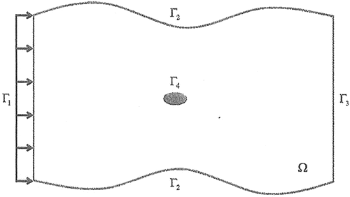
Figure 1. Computational domain.
4. Shape optimization
Consider an elliptic cylinder located in fluid flows as shown in Figure . The cylinder is subjected to fluid forces, consisting of drag and lift forces. The problem studied in this paper concerns which type of shape for the cylinder minimizes the drag force. As an index of the magnitude of drag force, a performance function is employed given by the square sum of the difference between the computed and objective forces. The coordinates on the surface of the cylinder are employed as the control variables. Thus, the problem is to find the surface coordinates of the cylinder that minimize the performance function under the constraints of the basic equations of fluid flows. In order to obtain the surface coordinates, the adjoint equation method is employed.
In this study, the minimization problem concerning fluid forces acting on a cylinder is considered. The performance function J is defined by the square sum of the fluid forces as follows:(20)
(20)
where denote weighting parameters,
represent drag and lift forces, and
are the objective fluid forces. For instance, in the case of the minimum drag force problem, the objective forces are given by
and
, with the others equal to zero. In the case of minimum lift force problem,
is taken to be symmetric on the upper and lower surfaces. In order to obtain the optimal shape, the performance function defined by the fluid forces should be minimized, satisfying constraint conditions given by the basic equations in Equations (14) and (15). The adjoint variables for the basic equation are defined as
and
. The performance function is extended by adding the inner product between the adjoint variables and Equations (14) and (15). The extended performance function
is expressed as follows:
(21)
(21)
Solving the minimization problem with the constraint conditions results in solving the stationary conditions of the extended performance function . The first-order adjoint equation is expressed as follows:
(22)
(22)
where denote the coordinates of the surface of cylinder on
node in the k direction, and
are the derivatives of the performance function corresponding to
.
The stationary condition means that the first variation of the extended performance function is equal to zero. Therefore, the first-order adjoint equations are obtained as follows:(23)
(23)
(24)
(24)
(25)
(25)
(26)
(26)
(27)
(27)
(28)
(28)
Then, the gradient used to update the surface coordinate can be derived as(29)
(29)
where is expressed as follows:
(30)
(30)
5. Minimization
It is necessary to preserve the volumeof the cylinder at the lth iteration cycle. A constant volumeis preserved, maintaining the volumeof the whole domain as follows:(31)
(31)
where represents the volumeof each element,
denotes the volumeof the initial domain, and
are the coordinates on the boundary of the cylinder at the lth iteration cycle.
A modified performance function can be introduced by adding a penalty term to the extended performance function, which is expressed as follows:
(32)
(32)
where l and are the iteration count and stabilizing weight, respectively, and
is an adjoint variable for the volumeconstraint. In the case that the modified performance function
converges to a minimum, the penalty term can be equal to zero. Minimizing the modified performance function
is equivalent to minimizing the extended performance function
. Thus,
(33)
(33)
By virtue of the stationary condition, the update of the coordinates around the cylinder is carried out by applying the following update equation:(34)
(34)
where(35)
(35)
It is necessary to determine the adjoint variable in order to preserve the volumeof the cylinder at each iteration. The variable
is obtained by setting the difference between the initial volumeand the present volumeto be zero:
(36)
(36)
By substituting Equation (34) into Equation (36), an implicit equation for can be obtained.
Figure 2. Computational domain.
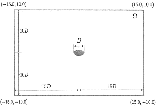
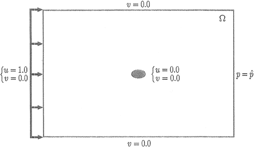
Figure 3. Boundary conditions.
6. Numerical study
Here, a drag force minimization problem is computed for an elliptic cylinder located in an fluid flow in an adiabatic state. The Reynolds and Mach numbers are given by and
. The ratio of specific heat is
. The computational domain and the boundary conditions are shown in Figures and , respectively. Constant flows with
and
are imposed on the inflow boundary. On the outflow boundary, the pressure is prescribed as
. On the boundaries at both sides, slip conditions are imposed, i.e.,
. The velocities on the surface of the cylinder are assumed to be zero. The density is taken to be
. The finite element mesh is illustrated in Figures and . The total numbers of nodes and elements are 6,188 and 12,128, respectively. The number of surface nodes of the cylinder is 128. An initial ratio of 1:2 for the vertical and horizontal lengths is employed. The adopted time increment is
.
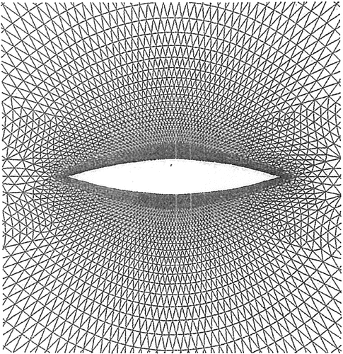
Figure 4. Finite element mesh.
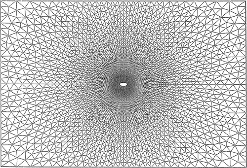
Figure 5. Finite element mesh around the cylinder.
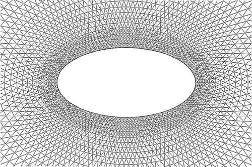
Figure 6. Performance function.
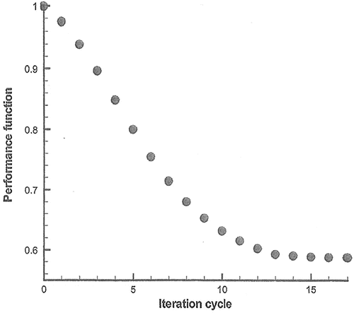
Figure 7. Time history of drag force.
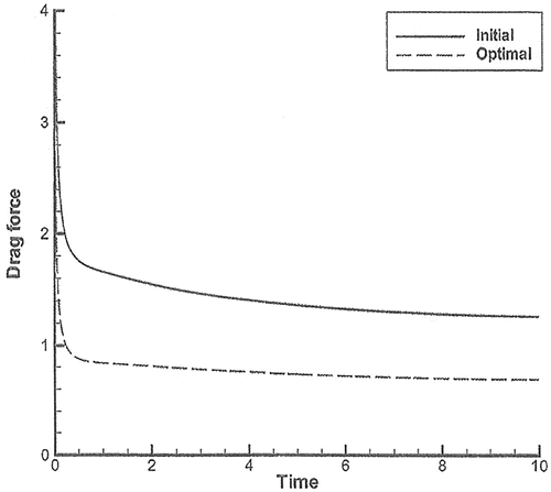
Figure 8. Finite element mesh of initial shape.
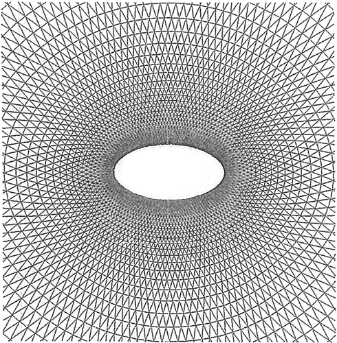
Figure 9. Finite element mesh of optimal shape.
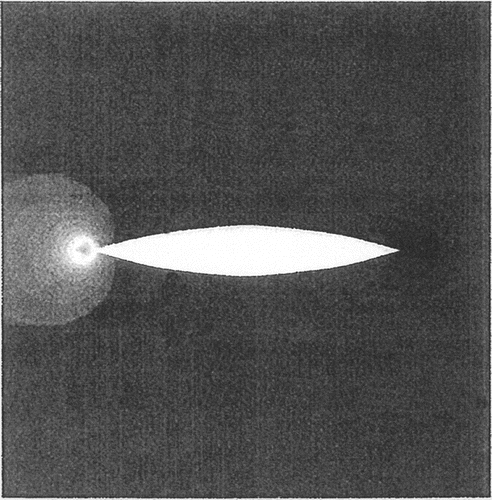
The variation of the performance function is illustrated in Figure . It can be seen that the ratio of J is reduced to 0.5881, which constitutes a reduction. The drag forces acting on the cylinder at the initial and final stages are illustrated in Figure . Figures and present the finite element mesh at the initial and final stages, respectively. A vertical ratio of 1:4.75 is attained. The shape at the final stage is the streamline shape. Figures and illustrate the pressure distribution. At the final stage, we observe that the pressure at the front part of the cylinder is significantly reduced.
Figure 10. Pressure distribution of initial shape.
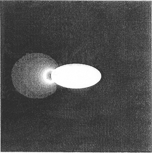
Figure 11. Pressure distribution of optimal shape.
7. Conclusion
In this paper, a shape optimization problem was presented regarding an elliptic cylinder located in fluid flows in an adiabatic state, and solved using the finite element method. The basic equations are formulated using the density and momentum as field variables. The finite element method using SUPG stabilization based on linear interpolation functions was effectively applied to solve the basic equations. The square sum of the drag forces acting on the cylinder, integrated over the working time, was introduced as the performance function. The weighted gradient method based on the adjoint equation was employed for the optimization. Precise forms of the SUPG finite element method based on the primitive variables, the adjoint equations, and the gradient of the performance function were concretely formulated. Starting with an elliptic shape, a streamline shape was obtained by performing a numerical computation using the proposed method. Thus, it has been demonstrated that the shape optimization method proposed in this paper is effective for practical engineering problems.
8. Funding
The authors received no direct funding for this research.
Additional information
Notes on contributors
Yuta Mochizuki
Yuta Mochizuki is a student of Department of Civil Engineering, Chuo University, Tokyo, Japan. He is now working for Tokyo Metropolitan Railway Co. Ltd.
Mutsuto Kawahara
Mutsuto Kawahara is professor of Emeritus, Department of Civil Engineering, Chuo University, Tokyo, Japan. His main research subject was the development of the numerical method, especially finite element method in fluid flows and shallow water flows. The optimization problems including force reduction and optimal estimation, etc. are recent research subject.
References
- Azegami, H. (2006). A smoothing method for shape optimization: Traction method using the robin condition. International Journal of Computational Fluid Dynamics , 3 (1), 21–23.
- Ishiyama, H. , & Kawahara, M. (2008). Shape optimization of body located in incompressible viscous flow. International Journal of Computer Mathematics , 85 , 1515–1530.
- Katamine, E. , Azegami, H. , & Ito, S. (2005). Solution to shape optimization problems of viscous flow fields. International Journal of Computational Fluid Dynamics , 19 (1), 45–54.
- Kawahara, M. , & Hirano, H. (1983a). Two step explicit finite element method for high reynolds number viscous fluid flow. Proceedings of the Japan Society of Civil Engineers , 329 , 124–140.
- Kawahara, M. , & Hirano, H. (1983b). A finite element method for high reynolds number viscous fluid flow using two step explicit scheme. International Journal for Numerical Methods in Fluids , 3 , 137–163.
- Kawahara, M. , & Miwa, T. (1984). Finite element analysis of wave motion. International Journal for Numerical Methods in Engineering , 20 , 1193–1210.
- Kawahara, M. (2016). Finite element methods in incompressible, adiabatic, and compressible flows . Japan: Springer.
- Maruoka, A. , Uchiyama, I. , & Kawahara, M. (2017). Finite element analysis of solitary wave propagation by acoustic velocity method. Computational Mechanics , 59 (1), 107–115. doi:10.1007/s00456-016-1337-4.
- Mohammadi, B. , & Pironneau, O. (2009). Applied shape optimization for fluids . Oxford: Oxford University Press.
- Nakajima, S. , & Kawahara, M. (2008). Shape optimization of a body in compressible inviscid flows. Computer Methods in Applied Mechanics and Engineering , 197 (51–52), 4521–4530.
- Nakajima, S. , & Kawahara, M. (2010). Two dimensional shape optimization using partial control algorithm and finite element method for compressible flows. Computer Methods in Applied Mechanics and Engineering , 199 (49–52), 3111–3124.
- Nasu, S. , Nojima, K. , & Kawahara, M. (2013). SUPG finite element method for adiabatic flows. Computers and Mathematics with Applications , 66 (3), 250–268.
- Ogawa, Y. , & Kawahara, M. (2003). Shape optimization of body located in incompressible viscous flow based on optimal control theory. International Journal of Computational Fluid Dynamics , 17 , 235–242.
- Okumura, H. , Hikino, Y. , & Kawahara, M. (2013). A shape optimization method of a body located in adiabatic flows. International Journal of Computational Fluid Dynamics , 27 (6–7), 297–306.
- Okumura, H. , & Kawahara, M. (2000). Shape optimization of body located in incompressible navier-stokes flow based on optimal control theory. Computer Modeling in Engineering and Sciences , 1 , 71–77.
- Sakamoto, M. , & Kawahara, M. (2010). Shape optimization of a body located in an incompressible flow using partial control algorithm. International Journal for Numerical Methods in Fluids , 67 , 1702–1719.
- Yagi, H. , & Kawahara, M. (2005). Shape optimization of a body located in low reynolds number flow. International Journal for Numerical Methods in Fluids , 48 , 819–833.
- Yagi, H. , & Kawahara, M. (2007). Optimal shape determination of a body located in incompressible viscous flows. Computer Methods Applied Mechanics and Engineering , 196 , 5084–5091.
- Yamazaki, D. , & Kawahara, M. (2009). Optimal control of temperature in fluid flow using four types of minimization techniques. Journal of Algorithms and Computational Technology , 4 , 207–230.
- Yoshida, H. , & Kawahara, M. (2008). Shape optimization of an oscillating body in fluid flow by adjoint equation and ALE finite element methods. International Journal of Computational Fluid Dynamics , 22 , 229–239.