 ?Mathematical formulae have been encoded as MathML and are displayed in this HTML version using MathJax in order to improve their display. Uncheck the box to turn MathJax off. This feature requires Javascript. Click on a formula to zoom.
Abstract
This paper considers the energy generation potential from swing and revolving door use. This involved modelling the mechanical work available from the single use of swing and revolving doors through consideration of the doors motion using Matlab. The equations of motion of swing and revolving doors were presented and several sources of harvestable mechanical energy were explored. The impact on the motion and energy generation potential of several parameters such as the door mass, door width and damping of the generator were considered. It was found that door use has potential for electrical energy generation. For a swing door somewhere in the region of 10 J could be expected from a single action. A revolving door was found to offer significantly greater potential were a user to rotate the door by 180°, this would be in the region of 40 J. This equates to an upper limit for the total energy generation potential over a 1 min period of 138 J for a swing door and 331 J for a revolving door. It was concluded that potential for the generation of electrical energy exists from door use. It was determined that this will be dependent on the generation method chosen and the type of door used, where revolving doors offer significantly more potential than swing doors for both a single occasion door use and over a 1 min period.
Public Interest Statement
The aim of this paper is to address the potential that exists for generation of electrical energy from the mechanical work input by a user to transit through swing and revolving doors. A mathematical approach has been taken to consider this, with several approaches to harvesting energy from door use have been considered. Each of these have been assessed in terms of the impact of an energy generation unit on the motion of the door and also the potential that then exists for generating electrical energy. The continuous use of each door type was also considered to determine the maximum achievable electrical energy output over the course of 1-minute. It was concluded that both swing and revolving doors offer potential for electrical energy generation.
1. Introduction
In recent years the need to consider alternative means of generating electrical energy has become apparent. Energy harvesting is one such source, that makes use of ambient energy sources to generate electrical energy, such as the movement of people through compartmented areas. It was seen in (Partridge & Bucknall, Citation2016) that despite inefficiencies in the process of converting the chemical energy contained in food into useful electrical energy through the process of energy harvesting, significant potential in the form of mechanical energy, particularly through walking, exists. In this paper another source of mechanical work that is widespread in the urban environment is considered, this being door use. Within this paper the potential for energy generation from a door opening event (DOE) is considered along with the utilisation of the available potential and is considered for both swing and revolving doors. The aim is to consider the potential for energy generation offered by both swing and revolving door use.
In terms of a commercially available device, Royal Boon Edam have developed the NRG + Tourniket, an energy generating revolving door, which is claimed to generate 10 W per passage to power the ceiling lamps in the door (Edam, Citation2015). It has been claimed that this saved 4,600 kWh/year of energy when installed in a railway station, however there is no indication as to how much of this was a result of the energy that was actually generated through use of the door (Edam, Citation2008). Additionally FLuxxlab have outlined the design of a number of door generators for swing, slide and revolving doors, however it is unclear how much energy these would generate (Fluxxlab, Citationn.d.). In addition, there is some literature available for both swing and revolving door harvesting devices. In terms of swing doors, several energy harvesting door systems have been presented in the literature (Litwhiler & Gavigan, Citation2014; Vignesh, Prasath, & Thiruvenkatam, Citation2015; Yildiz, Citation2010), however, the energy generated from a single use of a door has not been documented in these papers. Even so, in (Ahmad, Mazli, & Ariffin, Citation2016) an energy generation system was developed that directly utilised the motion of a swing door through a gearing system and dynamo. It was found that this produced an 11.54 V output and was deemed sufficient to charge a phone battery. In the work of (Hinge & Chaudhari, Citation2016) a generation unit has been developed to make use of the energy present from a user transiting through a swing door. This system uses the mass of the user on a plate installed on the floor to drive a dynamo through a rack and pinion system. This was found to produce in the range of 1.1–1.3 W during use. However, it should be noted that the source of energy in this system is the walking motion of the user as opposed to the user’s direct interaction with the door. A swing door generator utilising an AC stepper motor with appropriate power conditioning was developed in the work of (Zylka & Pociecha, Citation2016). Experimental testing revealed that 12.7 mJ of electrical energy could be generated from a single door use, however this reduced to 3 mJ when the power conditioning was included. It should be noted that the aim was to power a sensor node, which was achieved, as opposed to harvesting as much of the available potential as possible. A novel approach to harvesting energy from door motion was proposed by (Li, Citation2017), where PTFE electric film and Carbon-paper were used to exploit electrostatic induction as a means of harvesting mechanical work. A peak power output of ~3.24 mW was found and when tested in a door hinge, it was found that 47 LEDs could be lit by the generator. Similarly, for revolving doors, a number of energy harvesting devices have been presented (Ahamed, Rashid, Islam, Javed, & Yusof, Citation2016; Chavan, Patil, Patil, Nachare, & Bandagar, Citation2016; Gilani, Gilani, Baharudin, & Ibrahim, Citation2015; Murthy et al., Citation2011). In (Ahamed et al., Citation2016) the power output was found to be in the range of 1.564–2.6 W depending on the angular velocity of the door. In (Gilani et al., Citation2015) the energy generated from a single door use was found to be 15.67 J. In the work of (Mohurle, Deshmukh, & Patil, Citation2015) a number of human powered energy harvesting devices were developed for use in a garden. Amongst these was a revolving door which utilised a gearing system to directly harness the motion of the door to drive a generator. It was found that the power output is proportional to the torque applied on the motor shaft, where a peak output of 48 W was achieved for an applied torque (on the motor) of 7.5 Nm. The literature has revealed considerable work on energy harvesting from door use, however, this has mainly focussed on developing specific devices. One aspect that has not been considered in detail is the potential offered by swing and revolving door use and the impact of differing parameters of the door on the energy potential offered by door use.
The aim of this paper is to assess the potential for electrical energy generation that is offered by harvesting the mechanical work expended by people to operate swing or revolving doors. Further to this the impact on the available energy potential of different methods of generation and variation of the door parameters will be considered. This has been carried out by assessing the motion of a door based on the equations of motion as set out in Section 2 for swing doors and Section 3 for revolving doors. This is followed by a consideration of the application of energy generating doors in the urban environment in Section 4.
Within this paper two types of door that are common in the urban environment will be considered, namely swing doors and revolving doors. Swing doors consist of a door leaf that is rotated by a user applying an opening force as they transit the door, it then returns to its initial starting position through a door closing mechanism. A revolving door consists of a number of door leaves attached to a central beam around which the leaves rotate. The user is required to apply a force on one of these leaves to rotate the door through ~180° to transit the door. Unlike with swing doors, the revolving door is not required to return to its initial starting position after the user has transited but can instead just continue to rotate. As such a revolving door does not require a closing mechanism to apply a force to close the door.
2. Swing doors
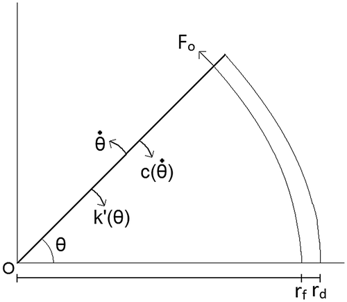
The methodology implemented for modelling the motion and energy potential for a swing door is as follows. A representation of the parameters used in determining the door’s motion are shown in Figure . Three approaches were considered for generating energy from a swing door, with the approaches considered laid out below.
| (1) | Method 1: The motion of the door directly drives a generator during opening and closing. | ||||
| (2) | Method 2: Energy was transferred to two springs during door opening. One of these was used to close the door, whereas the other drives a generator. | ||||
| (3) | Method 3: Replace the damping unit with an energy generation unit to act in place of the door damper. | ||||
2.1. Simple swing door
A simple swing door was modelled to act as the reference to which a generation system could be added. The door closer was considered to consist of a torsional spring, which was compressed as the door opens, with the energy then released to close the door. A viscous damper controls the velocity of the door during closing until the door reaches the latching angle. At this point the viscous damper stops acting on the door to allow the door to close properly. As such it was considered that there were four phases to be considered for a door opening event.
| (1) | The door is initially closed and at rest, with an opening force applied until the door angle reaches 60° open. This was modelled as a forced-mass-spring system, with a constant force applied. | ||||
| (2) | The door is then brought to rest as a result of the kinetic energy of the door being converted to potential energy in the spring. Modelled as a mass-spring system with initial conditions determined from the conditions at the end of phase 1. | ||||
| (3) | The door closes due to the energy stored in the spring acting on the door. The speed is regulated by a viscous damper, which offers critical damping. This is modelled as a mass-spring-damper system, with the initial conditions set by the end conditions from phase 2. | ||||
| (4) | Once the opening angle of the door reaches the latching angle, 7° (0.12 rad), the viscous damper no longer acts on the door, with the spring acting to fully close the door. A mass-spring system with initial conditions determined from the end of phase 3. | ||||
It was important to define a set of conditions, which are shown in Table , to determine the boundaries for each phase to be used in the Matlab models. These phase conditions were used to determine the initial and appropriate phase conditions for all of the swing door models.
Table 1. Boundary conditions used to determine the phase of the swing door’s motion
The motion is described in terms of the equations of motion for a rotating system, with each phase modeled with the appropriate equations of motion, as set out in Table , with the relevant parameters used defined as follows. The moment of inertia, I, is given by,
Table 2. The equations used to model the motion of a simple swing door
where r d is the width of the door and m d is the mass of the door. It is assumed that the mass of the door is distributed evenly across its width. The opening torque, τ 0, acting on the door is given by,
where F 0 is the magnitude of the force acting on the door, r F is the distance from the origin at which the opening force is applied and θ F is the angle at which the force is applied on the door. It is assumed that the force is applied perpendicularly to the door and hence θ F = 90o, thus sin (θ F) = 1. For simplicity a torsional spring with torsional spring constant, k′, is considered to act in closing the door. Hence the natural frequency, ω 0, is given by,
Using these values allows for the motion of a door with door closer to be modelled.
The constants used are defined as,
Phase 2 and 4 constants:
Phase 3 constants: C
2 = θ
0
The values of θ
0 and present in constants C
1, C
2 and C
3 are the initial conditions at each phase and were determined from the final values of the preceding phase. For phase 1, the values of θ
0 and
were assumed to be 0 rad and 0 rad/s respectively.
2.2. Method 1 (M1)
In order to model a generator on the door a number of modifications were required. This was carried out by modelling the generator as a viscous damper in the system. In method 1 the generator was assumed to be driven directly by the door’s motion, and hence the model was modified to take account of this. As a result, the phases of the swing door’s motion were modelled as follows,
Phase 1: The door was modelled as a Forced mass-spring-damper system, with constant force applied. The damper provides under-damping, with the value determined from the generation system.
Phase 2: A mass-spring-damper system with initial conditions determined from the conditions at the end of phase 1. The damping was the same as in phase 1.
Phase 3: A mass-spring-damper system, with the initial conditions set by the end conditions from phase 2. The damping was assumed to be critically damped and hence uses the same equation as for the basic door model. This was achieved by assuming that the swing door damper was adjusted such that the combined damping provided by the damper and generator remains critical.
Phase 4: The door motion was modelled as a mass-spring system and uses the same equations of motion as the basic door model.
To model these conditions, the equations of motion need to be significantly modified as shown in Table , with a number of additional parameters needing to be defined,
Table 3. Equations of motion used to determine the motion of a swing door, utilising method 1 of energy generation
where ω d is the damped frequency, ξ is the damping ratio, d g is the damping resulting from the generator and d c is the critical damping. The damping ratio was varied to represent the change in damping offered by the generator, where the damping ratio increases as the damping from the generator increases.
Phase 2 constants: C
4 = θ
0
2.3. Method 2 (M2)
The second approach considered for generation uses two springs, the first of these, k′1, is used to supply the energy required to close the door, whereas the second, k′2, is used to drive a generator. For this situation, the first two phases of the modelling are the same as for the basic door model. However, there are two aspects to the third phase. First, the energy stored in k′1 is used to close the door, with the damping still considered to be critical. The energy stored in k′2 is used to drive a generator independent of the door motion. A number of changes are needed to the basic swing door model in order to represent this. The value of k′ and ω0 for phases 1 and 2 are found using, k′ = k′1 + k′2. The second change in phase 3, where the natural frequency is now calculated with k′ = k′1. It is assumed that the damping provided by the swing door damper remains critical and hence varies as the value of k′1 varies. The potential for energy generation is found by simply determining the energy stored in the spring k′2. The energy in the spring is simply determined from the change in angular rotation of the spring and the torsional spring constant.
2.4. Method 3 (M3)
An alternative method proposed is to replace the viscous damper used to control the speed of the door during closing with a generator unit that provides damping to the doors motion through harvesting energy as a result of the motion of the door during closing. The motion of the door is the same as in the case of the basic swing door and hence the equations of motion laid out in Table are used. As such this method is considered to have an advantage over the two previously discussed, in that the door’s motion is unaffected by the presence of a generator unit. The energy available for generation is determined by the energy dissipated in the door damping unit. The method of generation could be realised by using a simple ratchet mechanism, whereby the generator is not engaged during door opening, but is engaged and driven during closing.
2.5. Energy
In order to explore the utilisation of the energy input in the process of opening the door, the energy involved is considered. The energy input into the system is considered to be made up of three components and is determined at the point where the opening force is no longer being applied,
where KE is the kinetic energy of the door, PE is the potential energy stored in the torsional spring and E go is the energy absorbed by the generator whilst the opening force is applied, t opening is the time over which the opening force is applied and τ g is the torque applied on the door by the generator. It should be noted that in the case of methods 2 and 3, E go = 0 J, since there is no generator acting on the door during opening. The total energy input into the system is the sum of these individual components of energy.
The energy output of the system for each of the generation methods is given by,
Method 1:
Method 2:
Method 3:
where t(θ max) is the time at which the maximum opening angle of the door occurs and t DOE is the time for a complete DOE to occur. From the values determined for E in and E gen, the ratio of electrical energy generated during door use to the total energy input during opening is referred to as the energy utilisation factor, UF, and is determined by,
An additional metric to be considered is the average power during door use, this takes into account both the total energy generated and the value of t DO and is calculated as,
Although the overall effect of a single DOE may not seem significant, if the door is to be used by multiple users, the value of t DOE would help determine the maximum number of times the door can be operated over a given period of time and will hence affect the maximum energy output. As such the value of t DOE will play an important role in determining the total energy generated in a practical situation. For a swing door, the value for t DOE is considered to be the time from when the opening force is first applied on the door to when the door position had returned to an angle of 0°. It should of course be noted that in actuality, the flow of people through a swing door will likely lead to the situation where the door is held open for multiple users to pass through, hence significantly reducing the number of swing activations of the door and total energy generated even though the throughput is high. The values determined for the total energy generated in this paper represent the maximum achievable values and act as an upper limit of the achievable outputs.
The mechanical work available from door use can be converted into electrical energy. It is assumed that this can be simply carried out with an electromagnetic generator. For both swing and revolving doors it is assumed that a conversion efficiency, η, of 56 % would be achievable (Partridge & Bucknall, Citation2016).
2.6. Parameters
A number of parameters need to be assigned before the calculations can be completed and were set as shown in Table , to provide the baseline case. The values of the m d, k′ and r d parameters were then independently varied, while the baseline values were maintained constant for the remaining parameters. The ranges assigned to the parameters were, m d = 10–140 kg, k′ = 4–14 Nm/rad and r d = 0.5–1.5 m. It should be noted that in all cases, it was assumed that the opening force was applied at a radius, r F, of 0.1 m from the outer edge of the door.
Table 4. Parameters values utilised for baseline calculations
2.7. Discussion
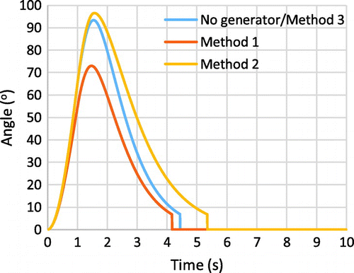
For the swing door model, three methods were considered for harvesting the mechanical energy associated with door use. The first test was to compare the motion of the door for each of the methods as well as to the non-generating swing door model, as can be seen in Figure . It was observed that method 1 resulted in a decrease in the final opening angle of the door due to the retarding effect of the generator on the motion of the door and also a decrease in the value of t DOE. It is worth reiterating that the opening force was applied on the door until the opening angle reached 60°, this was to ensure that the door was opened sufficiently for the user to pass through the door. It must be noted that in reality it is likely that the user would adjust the opening force applied on the door when in transit depending on the resistance of the door to opening, i.e. a door that has a higher resistance to opening would be opened with a greater force by the user than one with a lower resistance to opening. This would impact the final opening angle of the door, with the likely outcome that the final opening angle of the door would be similar regardless of the resistance to opening. The exact change in opening force/time of force application would likely vary depending on factors such as the individual user and the user’s prior knowledge of the particular door, hence determining a realistic interpretation of the user’s response to a door’s opening resistance would be a complex problem in itself. Due to this and that the focus of this paper is on the impact of different generation methods it was decided that an opening force would be applied until the door angle reaches 60° in order to meet the basic requirement that the user can transit through the door but also to keep the energy required to open the door as a constant and allow a more direct comparison of the impact of different generation methods. Method 2 had no impact on the motion of the door during opening since the value of k′ is constant, however the closing time increased due to the decreased closing force offered by the closing spring. Method 3 has no impact on the motion of the door.
Figure 2. Comparison of the angular position of the door when no generator is present with the three methods of generation.
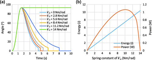
In method 1 the generator was modeled to act as a viscous damper with the proportion of damping, ξ, given as a proportion of critical damping. It was seen from Figure (a) that an increase in the value of ξ resulted in a decrease to the maximum opening angle of the door. The time taken for the door to reach θ max increased and there was a slight increase to the value of t DOE. It was found that the value of E gen increased with ξ up to a value of 9.8 J/DOE, there is a similar increase in the value of P ave with a maximum of 2.1 W, as is shown in Figure (b). The maximum opening angle for method 2 was unchanged by variations to k′2, as the total value of k′ during opening remains constant as it was the sum of k′1 and k′2. Variations to k′2 significantly impact on the motion of the door during closing, where an increase in the value of k′2 resulted in an increase in the time taken for the door to close, as was seen in Figure (a). This was because as k′2 increased, k′1 decreased meaning that the net force acting to close the door was reduced. The energy potential available for harvesting increases linearly as the value of k′2 increases, as is shown in Figure (b). This was because the maximum opening angle of the door was the same regardless of the proportions of k′1 and k′2, meaning the energy stored in spring k′2 was proportional to the value of the torsional spring constant. A maximum value was found for k′2 = 14 Nm/rad, where the energy stored was 10.26 J. However, in this case the door remains open since no force is available to close the door. It must be noted that the maximum value of stored energy is dependent on the value of k′ and the ratio between k′2 and k′1, where an increase in the value of k′2 would result in an increase to the total energy stored if the final opening angle of the door were to remain the same. Although the value of E gen increased with k′2, the value of P ave peaked at 1.07 W where k′2 = 10.3 Nm/rad. This is due to the increase in the value of t DOE with k′2. It was found that for variations to ml and rd, the peak value for the average power occurred at the same value of k′2, furthermore for variations of k′, the ratio of k′2/k′ that produced the highest peak output was constant at 0.74. For method 3, the value of E gen was found to be 10.17 J/DOE, with a value of t DOE of 4.42 s, giving a value of Pave = 2.30 W. It should be noted that the value of E gen in method 3 was calculated using the assumption that the generator is providing critical damping to the swing door.
Figure 3. Angular position of the door during a door opening event for method 1. The damping effect of the generator (ξ) on the door is varied. Energy potential available for harvesting from method 1 as a function of the damping effect of the generator.
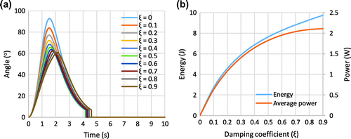
Figure 4. The angular position of the door using method 2 for varying proportions of the torsional spring constant of springs 1, k′1, and 2, k′2.
For all three methods of generation, the total value of E in was 36.66 J. This was determined as the total energy in the system at the point when the opening force ceases to be applied, as the potential energy stored in the spring is the same for each scenario, since the opening force is applied until the door angle is 60o and the torsional spring constant is the same for each method. In the case of method 1, the KE of the door decreases as the value of ξ increases, but this is matched by an increase in the value of E go. For methods 2 and 3, the KE energy of the door is the same for all values of k′2, since the door’s motion during opening is unchanged.
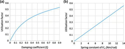
The utilization of the energy input into the system is shown in Figure (a) and (b) for methods 1 and 2 respectively. It is apparent, that when ξ = 0 for method 1 and k′2 = 0 Nm/rad for method 2, the output power and hence UF will be equal to 0, since there is no means of energy generation. Since the value of E in is constant for all three methods at 18.33 J, then the UF is a function of the value of E gen. This reaches a peak of 0.531 for method 1 and 0.560 for method 2. It should be noted that for method 2, this coincides with a value of k′2 of 14 Nm/rad (k′1 = 0 Nm/rad) and hence there is no closing force available to shut the door. As such the value with the maximum value of P ave is taken, where UF = 0.411, where k′2 = 10.3 Nm/rad. Method 3 resulted in the highest practical value of UF, where a value of 0.555 was determined. For method 3, the value of UF is a direct result of the generator efficiency. Since the generator has been assumed to replace the door damper, all of the available potential is utilised and hence the value of UF is really a reflection of the generator efficiency. As such a different assumption for the generator efficiency would directly impact the value of UF.
Figure 5. The utilisation factor for (a) Method 1 as a function of the damping coefficient, ξ, and (b) Method 2 as a function of k′2.
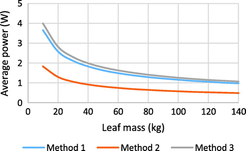
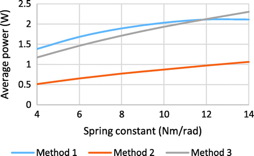
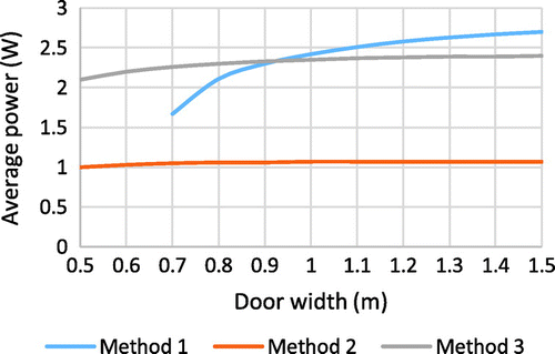
The final stage was to investigate the effect of varying the values of the parameters of the door. The parameters chosen were the mass of the door leaf, m d, the torsional spring constant, k′, and the width of the door, r d. The value of ml was varied from 10–140 kg. It was found that E in, E gen, UF and θ max all remained constant for each of the generation methods. Although an increase to the door leaf’s mass increased its inertia, it was found that this resulted in a smaller angular velocity at the point where the opening force was no longer applied. There was however a significant impact on the value of t DOE and therefore P ave, due to the change in the inertia of the door. As can be seen in Figure , the average power decreased as m d increased, with the largest impact occurring for small values of m d. It was therefore determined that minimising the mass of the door would be beneficial in increasing the energy potential, since although the generated energy remains constant, the reduced value of t DOE with decreased ml would allow for more operations of the door in a given time. For variations to k′, it was again found that there was no change in the value of E in. For methods 1 and 3, the value of E gen and E util decreased slightly as k′ was increased, however for method 2 they remained constant. For each of the methods there was a significant impact on the values of θ max, t DOE and P ave, where θ max and t DOE decreased as k′ increased. From Figure , it can be seen that P ave increases with k′ for each generation method, this is due to the decrease in the value of t DOE and is most pronounced for method 3. It was determined that although the energy output is unaffected by the value of k′, an increase in k′ results in an increase to P ave, due to the reduced value of t DOE. The final parameter to be varied was the width of the door, impacting on both the inertia and opening torque applied to the door. For each method there was a significant increase to E in, E gen and θ max for increase r d. The value of E util increased slightly for method 1 from 0.527 to 0.541 for r d of 0.7 and 1.5 m respectively and for method 3 from 0.5512 for r d = 0.5 m to 0.5574 for r d = 1.5 m, but remained constant for method 2. The value of t DOE increases for each method with increased r d. The value of P ave increases for each method, although this is nominal for method 2, method 3 increases slightly, whereas for method 1 the increase is significant, as can be seen in Figure . It was determined that increasing the value of r d improves the potential for energy generation.
A comparison between the three methods of energy generation suggests that method 3 offers the best potential in terms of energy and average power and has the additional advantage of not impacting the motion of the door during use. This is to be expected, since in method 3 the generator is assumed to directly replace the door damper and hence all of the input energy has been utilised for energy generation. This is reflected in the value of UF, where for method 3 this is solely determined by the assumed generator efficiency. In contrast methods 1 and 2 utilise a door damper in addition to a generator to limit the swing door’s motion. The energy dissipated in the damper is therefore not utilised for energy generation and hence results in lower values of UF for methods 1 and 2.
3. Revolving doors
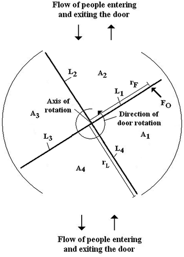
The revolving door was modelled using a different approach, since there is no need for the door to return to its original position during use. For a swing door three approaches to door operation for energy generation were considered, however, for the revolving door it was considered that the motion of the revolving door would directly drive the generator and the generator was again assumed to act as a viscous damper. The layout of the revolving door is shown in Figure .
A number of assumptions were made with regards to the door. The door is considered to be a four-leaf revolving door, where the angle between each leaf was set at 90° and each leaf is assumed to be identical with mass, m L, and radius from the point of rotation, r L. This results in the inertia of the door, I, being given by,
where I L is the inertia of each door leaf. The opening force, F O, is applied perpendicular to the face of the door, at a distance r F from the axis of rotation, where r F = r L – 0.1 m in this paper. The opening torque, τ O , acting on the door and the torque applied by the generator to retard the motion of the door, τ G , are given by,
where d g is the damping of the generator. In addition, it was deemed that the door is required to rotate through 180° for a user to pass through. As such the opening force was applied until the angular position of the door reached 180°. It was assumed that the door was manually operated and that the generator acted as a damper on the door’s motion.
The motion of the door was considered to consist of two phases. Initially the door was at rest. An opening force (F
O) was applied perpendicular to the door’s leaf surface by the user on one of the door’s leaves and acted to rotate the door. The presence of a generator acts to dampen the motion of the door with the retarding torque being dependent on the angular velocity of the door. The calculation of the door’s motion was calculated using the equations set out in Table . It is worth noting that ∆t = 0.001 s for the whole simulation. The opening force is applied until the angle through which the door has rotated is 180°. At this point the opening force is no longer applied, resulting in τ
O
= 0, and the door decelerates due to the damping provided by the generator. The initial conditions were set as follows, ,
and
. It should be noted that when determining
, the inertia of the door, I, is used as opposed to the inertia of each door leaf, I
L. This is because each of the door leaves are assumed to be connected in a rigid structure and hence the opening torque applied by the user is required to accelerate the whole door.
Table 5. Equations used to determine the motion of a revolving door
3.1. Parameters
As with the swing door a number of variables were varied in order to test their effect on the energy potential and value of t DOE. The baseline values used are shown in Table . The values of m L, d g and r L were independently varied with values of m L = 16–80 kg, d g = 4–100 Nms and r L = 0.5–1.5 m. It should be noted that an increase in m L will result in a linear increase in I L .
Table 6. Parameters chosen for the baseline case of the revolving door
3.2. Energy
The energy generation and energy utilisation from a revolving door was determined as follows,
This is very similar to the swing door, however there is no longer need for a spring to store energy to close the door. The total energy input to the system is the sum of these individual components of energy.
The output energy of the system is given by,
The ratio of electrical energy generated during door use to the total energy input during opening is referred to as the energy utilisation factor and is given by,
The average power is determined in the same way as for the swing door. For a revolving door, the value of t DOE is considered to be from when the opening force is first applied, until the door comes to rest. Since the door is critically damped the speed of the revolving door never fully returns to 0 rad/s, as such it was considered that when the speed of the door fell below 0.01 rad/s the door was deemed to be at rest. An additional consideration for the revolving door is that it can continue to rotate and can hence continuously rotate. As such it is also necessary to consider the power output whilst in constant use.
3.3. Results
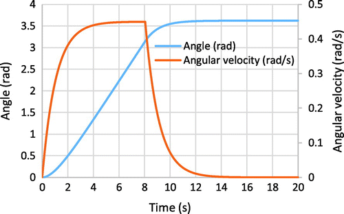
An initial baseline example was considered where, m L = 40 kg, F O = 25 N, r L = 1.0 m and d g = 50 Nms with the results shown in Figure .
3.4. Discussion
The motion of a revolving door differs significantly from that of a swing door, due to the lack of a need for a door closing unit and also the increased time expected for a user to pass through. The motion of the door for the baseline case can be seen in Figure . The two phases can be clearly discerned, where in phase 1 the door accelerates and approaches a speed of 0.45 rad/s. The opening force is maintained until the door has rotated through an angle of 180° (π rad) at 8.05 s, where the opening force is no longer applied and the door quickly decelerates before coming to rest. The total angle through which the door has rotated is 3.61 rad and the total energy generated was found to be 39.59 J/DOE with a UF of 0.560. The value of UF is determined from the ratio between energy generated and energy input by the user and in the case of a revolving door, this will be dependent only on the assumed efficiency of the generator. This is because all of the energy input by the user is utilised by the generator to limit the motion of the revolving door. Hence, the value of UF for a revolving door will be the same in all cases in this paper due to the assumption made with regards to the generator efficiency. Evidently the angle through which the door rotates will impact upon the initial position of the door for the next user, however for the purposes of this paper this has been ignored.
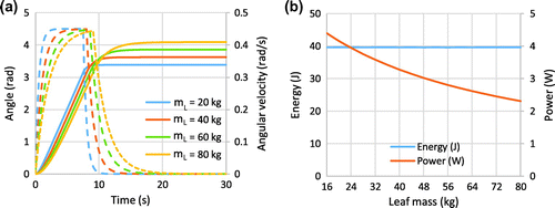
It was found that Increases to the door leaf mass resulted in both an increased length of time for the door to rotate through 180° and an increase in the time for the door to come to rest once the opening force was no longer applied, both as a result of the increase in inertia of the door. As a consequence, the total rotational angle of the door increased with mass, as can be seen in Figure (a). The total energy generated remains constant for all value of the door leaf mass at 39.59 J/DOE. The average power generated decreases as the door leaf mass increases, with a peak of 4.38 W for a leaf mass of 16 kg, as can be seen in Figure (b), due to the increase in t DOE. For a single door use this makes little difference since the total energy generated is a constant, however if there are multiple users then the number of users able to transit through the door and hence total energy generated over a given period of time will be affected. The utilisation factor remains constant at 0.560. As a result, it was determined that decreasing the mass of the door leaf would not impact the energy generation potential of a door, however it may have a beneficial impact due to the increased average power output resulting from the decrease in t DOE. It must be noted that as with the swing door, if the door has a higher resistance to opening, then the user is likely to use a greater force to open the door, however, as has been previously stated, interpreting a user’s response to a specific door will be a complex problem and is not the purpose of this paper.
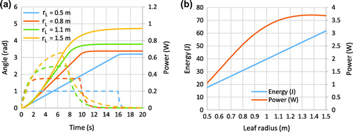
Figure 11. Results for variations to the leaf mass, m L, (a) Revolving door angular rotation (solid lines) and angular velocity (dashed lines) (b) Total energy generation potential and average power output.
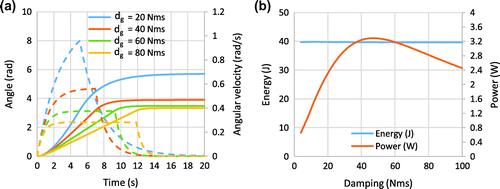
Increasing the damping effect of the generator reduces the maximum speed and increases the time for the door to rotate through 180°, as can be seen in Figure (a). The value of t DOE. however reached a minimum at d g = 48 Nms with a value of 12.09 s. It was found that the value of the damping coefficient did not impact upon the energy generation potential, which remained constant at 39.59 J/DOE. The average power peaked at 48 Nms with a value of 3.28 W, as is seen in Figure (b). This was primarily due to the impact of the value of t DOE. The energy utilisation factor remains constant for all values of d g at 0.560. It was concluded that the appropriate choice of damping from the generator will impact the average power generated during door use and will hence need to be assessed based on the specific door.
Figure 12. Results for variations to the generator damping, d g, (a) Revolving door angular rotation (solid lines) and angular velocity (dashed lines) (b) Total energy generation potential and average power output.
Increasing the leaf radius results in an increase to the maximum angular velocity and final angle of the door, as can be seen in Figure (a). It is worth restating that the opening force is applied perpendicular to the leaf and at a radius, r F, of 0.1 m less than the leaf’s radius, r L. Thus an increase in the leaf radius results in an increase in the torque applied to open the door. It was found that the generated energy increased linearly with the leaf radius, from 17.59 J/DOE for r L = 0.5 m to 61.59 J/DOE for r L = 1.5 m. The value of Pave, peaked at a value of 3.69 W for r L = 1.4 m as can be seen Figure (b). The average power then begins to decrease, due to the increase in the value of t DOE. The utilisation factor remains constant at 0.560. It was determined that the generated energy output increases with leaf radius, however the average power plateaued at r L = 1.1 m.
4. Comparison
A comparison between the energy generation potential and average power output of swing and revolving doors shows that there is a significant increase for revolving doors over all of the swing door methods of generation. This however, came at the cost of an increase in the time taken for a user to transit the door and to the energy input required from the user. In part this is due to the difference in the angular rotation of the door required for a user to transit. The revolving door does not require a closing mechanism to shut the door after the user has transited and as such all of the energy input by the user is utilised for energy generation. Similarly, for method 3 of the swing door, it has been assumed that the door damper has been replaced by a generator. In this case all of the energy input by the user is utilised by the generator. As a result, the value of UF is greater for a revolving door and for method 3 of the swing door than for methods 1 and 2 of the swing door.
5. General application
Thus far the energy output from a single use of swing or revolving doors have been considered, however if the door generating device is installed, how much energy could be expected to be generated? To consider the limitations to this, the potential for energy generation over a 1 min period was considered, where the door was in constant use. Constant use of the door simulates the maximum achievable energy output over a 1 min period and as such acts as an upper limit for the expected output from a given door. To do this the generated energy from each method of door use was considered based on the baseline values. Examples of the motion of a swing door and revolving door are shown in Figures and respectively.
Figure 14. Continual operation of a swing door over a 1 min period, utilising generation method 3 and the baseline values for door parameters.
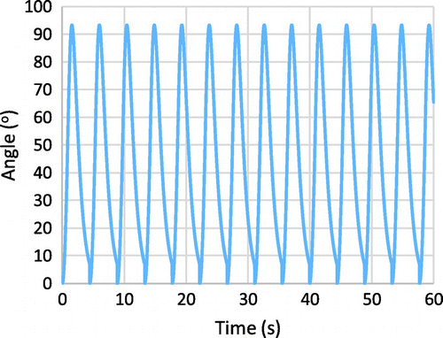
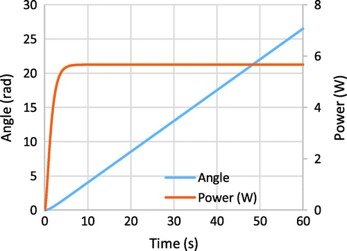
Figure 15. Total angular position and output power for a revolving door during continuous operation for a 60 s period.
In the case of swing doors, the motion of the door is such that the door is opened by a user with the door allowed to fully close. As soon as the door has returned to its starting position, the door is then opened again by another user and continues in this vain until the 1 min time period is completed. For methods 2 and 3, the energy generated is split into pulses that occur each time the door closes. On the other hand, for method 1, there is nearly always a power output, since the door is nearly always in motion and the door’s motion directly drives the generator. The power output does however vary due to the differing angular velocity of the door during the door opening event.
Revolving doors differ to swing doors in the sense that the door is not required to return to a closed state before generation can continue, hence if two users were to follow directly after each other, then the door could continue to be used and the angular velocity and power output would remain at the maximum values. As such the results for a 60 s period of continuous operation are presented in Figure . The output power increases as the door is first operated as a result of the increase in the angular velocity, it then reaches a maximum value of 5.67 W, as the angular velocity reaches its maximum value of 0.450 rad/s. The value of E gen over this period is 331.20 J with a value on E in = 596.83 J, resulting in a value of 0.555 for the utilisation factor.
The result for the maximum generated energy output are shown in Table , it is clear that for swing doors, method 2 is the worst performer due to both the lowest energy output per door use and the increased time taken for a DOE to occur giving it the lowest value for both the maximum achievable output and number of uses. Method 3 gives the best results both in terms of both energy output and number of possible uses. It has the additional advantage that the motion of the door is unaffected by the presence of a generator since the generator is replacing the damping unit used to limit the angular velocity of the door during closing. As such it appears that for swing doors, method 3 offers the best solution for harvesting the energy potential. In terms of the revolving door, the maximum energy potential is significantly higher than for any of the generation methods applied to a swing door. In part this stems from the increased energy output of a revolving door, but is also a result of the removal of the requirement for the door to be shut, as is the case for a swing door. This allows the door to be continually operated with the motion of the angular velocity of the door increasing as the first user enters but then being maintained at a value of 0.45 rad/s during continued operation.
Table 7. Limitation to the maximum achievable generated energy using the baseline values for each of the methods of door generation
The values presented in Table are the maximum achievable values that could be expected from each of the generation methods when using the baseline values for the door parameters. It is tempting to consider that the total energy generated by a door over a given period of time will simply be the energy generated from a single door use multiplied by the number of users, however it is clear that this is unlikely to be the case particularly since most doors will experience significant fluctuations in the number of users. It is clear from Table that the number of uses possible for the swing door are greater than those of the revolving door, particularly for methods 1 and 3. It should be noted at this point that for the revolving door one use is considered as the door rotating through a 180° angle. However, this is based on an ideal situation where there is a constant flow of users, separated such that each new user enters the door at the same time as the previous door opening event concludes. In reality this is very unlikely to occur. It is evident that if the number of users is lower than the maximum achievable number of uses then this would negatively impact the energy generated since the maximum number of door opening events is limited by the number of users that transit through the door. A similar impact will also be seen for swing doors if the flow rates are higher than the maximum achievable number of uses. In this case the door would be unable to close before the next user begins transiting through the door. As such the door will not be able to utilise all of the potential of the previous user and will require a smaller input from the next user, since the angle through which the door is required to move is decreased. It is expected that this situation would occur for flow rates significantly below the maximum achievable flow rate since the distribution of users is unlikely to be even but also users are likely to hold the door open for another user if they are nearby. In the worst case scenario, it is highly likely that in cases of very high flow rates, the swing door would simply be held open with multiple users passing through the door for a single door use. This would significantly reduce the total energy output from the door. This is not the case for a revolving door, where the door would still be required to rotate to allow a second user to pass through. As such the total energy output would remain the same for a revolving door. Even so for high flow rates of users through a revolving door, the average energy input from each user would still decrease since multiple users can pass through at any given time, even if it is assumed that only one user is able to enter each of the four sections of the revolving door. If the revolving door is at rest, then the first user will be required to rotate the door 180o to transit the door, however if a second user were to enter after the door had rotated 90o, then the second user would only be required to rotate the door by a further 90o after the first user has left, with the possibility that each additional user is only required to rotate the door by a further 90o. Although this would not reduce the total energy generated, it would lower the average energy generated from each user.
6. Conclusions
It was concluded that there is potential for electrical energy generation through the utilisation of the mechanical work carried out during use of swing and revolving doors.
In terms of swing doors, 3 methods of generation were explored where an energy generation potential of ~10 J/DOE was found for each method. It was found that methods 1 and 3 offered the best potential in terms of the average power output since the implementation of method 2 would significantly increase the time taken for the door to close. It was found that the average power output from a swing door increased for a decrease in the mass of the door and for an increase in the torsional spring constant and door width. Finding the optimal parameters will depend on the location at which a door is to be installed.
It was found that revolving doors offer far higher potential for energy generation than swing doors, with an output in the region of 40 J/DOE. As with swing doors it was found that decreasing the mass of the door resulted in an increase to the average power output. The damping offered by the generator was found to impact the time of a DOE. The width of the door resulted in an increase to both the value of generated energy and average power output. An additional advantage of a revolving door was that it can be operated continuously with respect to generating electrical energy since there is no need for the door to return to the closed state before the next operation. Although this did not impact on the energy output, it did significantly increase the average power output.
When considering the energy output from a swing or revolving door, it was found that the revolving door offered a significantly larger generated energy output than a swing door. This was due to both the increased energy and average power outputs of a revolving door and also the continuous generation of electrical energy that can be achieved with a revolving door.
| Nomenclature | ||
|
| = | damping applied to limit the door’s motion |
| d g | = | damping resulting from the generator |
| d c | = | critical damping |
| E gen | = | electrical output energy |
| E go | = | energy input into the generator |
| E in | = | energy input into the system |
| F O | = | opening force |
| I | = | moment of inertia |
| I L | = | revolving door leaf moment of inertia |
| k′ | = | torsional spring constant |
| k′1 | = | torsional spring constant for the door closer |
| k′2 | = | torsional spring constant for driving the generator |
| KE | = | kinetic energy |
| m d | = | swing door leaf mass |
| m L | = | revolving door leaf mass |
| P ave | = | average power output |
| PE | = | potential energy |
| r F | = | radius at which the opening force is applied |
| r d | = | swing door leaf radius |
| r L | = | revolving door leaf radius |
| t DOE | = | time for a door opening event to occur |
| t opening | = | time at which the opening force ceases to be applied |
| UF | = | utilisation factor |
| ξ | = | damping ratio |
| Ψ | = | phase angle at the start of this phase |
| η | = | generator efficiency |
| θ(t) | = | door leaf angle at time t |
|
| = | door leaf angular velocity at time t |
|
| = | door leaf angular acceleration at time t |
| θ F | = | angle at which the opening force is applied on the door leaf |
| θ max | = | maximum opening angle of the door leaf |
| θ 0 | = | initial angle of the door leaf |
| θ 0 | = | initial angular velocity of the door leaf |
| τ g | = | torque applied on the generator |
| τ 0 | = | opening torque applied on the door leaf |
| ω d | = | damped frequency |
| ω 0 | = | natural frequency |
Funding
This work was financially supported by Engineering and Physical Sciences Research Council [grant number EP/G037698/1].
Acknowledgements
I would like to acknowledge the contributions of Mr Konrad Yearwood in providing assistance in proof reading the article.
Additional information
Notes on contributors
J.S. Partridge
J.S. Partridge is a post-doctoral researcher associate in the Department of Mechanical Engineering at University College London. He received his EngD in Urban Sustainability and Resilience in 2015 and an MSc in Power System Engineering, both at UCL. Prior to this he received a BSc (Hons) in Physics from the University of Warwick. His current research interests include energy harvesting, fuel cell powered automotive drive trains and wireless charging of electric vehicles.
References
- Ahamed, R. , Rashid, M. M. , Islam, J. , Javed, A. , & Yusof, H. M. (2016). Energy generation from revolving door. Indian Journal of Science and Technology , 9 (19), 1–6 http://doi.org/10.17485/ijst/2016/v9i19/84237
- Ahmad, S. A. , Mazli, M. N. I. , & Ariffin, M. K. A. M. (2016, November 14–16). A mechanical design of power generator using door openings for household use. In 2016 International Conference on Advances in Electrical, Electronic and System Engineering . Putrajaya.
- Chavan, P. , Patil, N. , Patil, P. , Nachare, M. , & Bandagar, B. H. (2016). Experimental study of revolving door at Amgoi campus. In International conference on recent trends in engineering and management (pp. 1065–1072). Kolhapur.
- Edam, B. (2008). Edam, The Netherlands – November 2008 Boon Edam introduces the world’s first energy generating revolving door . Retrieved from https://www.greenbiz.com/article/worlds-first-green-revolving-door-good-turn-generates-energy.
- Edam, B. (2015). NRG+ tourniket . Retrieved from https://www.greenbiz.com/article/worlds-first-green-revolving-door-good-turn-generates-energy
- Fluxxlab . (n.d.). Fluxxlab . Retrieved August 18, 2015, from http://www.fluxxlab.com/projects/
- Gilani, S. F. , Gilani, S. I. , Baharudin, Z. , & Ibrahim, R. (2015). Development of energy harvesting system using rotation mechanism of a revolving door , 10 (21), 10159–10163.
- Hinge, H. , & Chaudhari, P. E. (2016). Door based power generation system and automatic opening of door , 4 (4), 72–77.
- Li, S. (2017). Double-folding paper-based generator for mechanical energy harvesting , 10 (1), 38–43. doi:10.1007/s12200-016-0658-4
- Litwhiler, D. H. , & Gavigan, T. H. (2014). A door motion energy harvesting system for powering an electronic door lock. In 4th IAJC/ISAM Conference Proceedings . Orlando, FL.
- Mohurle, M. P. , Deshmukh, D. S. , & Patil, P. D. (2015). A review on human power utilization for direct and electricity generation , 4 (1), 30–36.
- Murthy, M. S. , Patil, Y. S. , Sharma, S. V. K. , Polem, B. , Kolte, S. S. , & Doji, N. (2011). Revolving doors producing green energy . 2011 IEEE 1st Conference on Clean Energy and Technology, CET 2011, 157–160. http://doi.org/10.1109/CET.2011.6041478
- Partridge, J. S. , & Bucknall, R. W. G. (2016). An analysis of the energy flow and energy potential from human energy harvesting with a focus on walking. Cogent Engineering , 3 (1), 1215203. doi:10.1080/23311916.2016.1215203
- Vignesh, S. , Prasath, N. V. , & Thiruvenkatam, S. (2015). Design and analysis of door harvesting energy. Journal of Applied Sciences Research .
- Yildiz, F. (2010). Low-power energy harvesting from hydraulic door closer. Journal of Engineering Technology , 27 (1), 18–25.
- Zylka, P. , & Pociecha, D. (2016). Harvesting energy from human kinesis for indoor environment sensing. In 14th International Conference on Optical and Electronic Sensors, 2016, Gdansk, Poland. http://doi.org/10.1117/12.2244997

