 ?Mathematical formulae have been encoded as MathML and are displayed in this HTML version using MathJax in order to improve their display. Uncheck the box to turn MathJax off. This feature requires Javascript. Click on a formula to zoom.
Abstract
In this paper, a biomechanical model of human body is proposed to evaluate the biodynamic responses to vertical vibration and transmitted accelerations for the seated position without backrest support. Hence, a 6-DoF lumped-parameter model with six concentrated masses, which are connected using several linear springs and dampers, is presented here. Moreover, the full vehicle model is developed in ADAMS/CAR in order to utilize the acceleration of seat under various roads excitation for different amount of vehicle speeds. The transmitted accelerations to the human body segments are evaluated based on applied accelerations under the automotive passenger’s seat due to, two various road profiles with two driving cycles. The road profiles consisted of polyline and roughness profiles. Finally, the obtained results illustrated the maximum value of transmitted accelerations for different body segments occurred in frequencies below 5 Hz, it can be concluded that the human body is more sensitive to vibration with frequencies under 5 Hz.
Public Interest Statement
In this paper, a biomechanical model of human body is proposed to evaluate the biodynamic responses to vertical vibration and transmitted accelerations for the seated position without backrest support. This type of model is used for evaluating a vehicle concept design, instead of a real human. In that model 6 lumped mass is used as human body important parts. And then 7 pairs of springs and dampers added, rather than muscles and some organs those hold other members together. Then the model has been jointed with a car software model. Simulating both body and car models simultaneously showed that human body is more sensitive to vibrations below 5 Hz frequencies.
1. Introduction
Investigation of vibrations transmitted from automotive to the human body, for evaluating comfort parameters, always has been a concern for car manufacturers. The biomechanical models include lamped parameter, multi body and finite element models, which among all the accuracy of lumped parameter models are proved to be capable of assessment vibration in one direction.
Many lumped parameter models have been proposed for various applications. For example, Allen (Citation1978) presented a 2-DoF biomechanical model which this linear model utilized in other works in order to assess automotive comfort quality. Suggs, Abrams, and Stikeleather (Citation1969) created a 3-DoF biomechanical model which has been used for years to assess automotive comfort. And also, Wan and Schimmels (Citation1995) proposed a 4-DoF biomechanical models for the seated posture which utilized to study human-automotive system responses and evaluation quality comfort by Wagner and Liu (Citation2000). Muksian and Nash (Citation1976) created a nonlinear 6-DoF biomechanical model while the addition of this model is completed with spring and damper by Patil, Palanichamy, and Ghista (Citation1977). Moreover, this model utilized in a tractor model to evaluate driver-tractor system vibrating responses Patil, Palanichamy, and Ghista (Citation1978) and (Patil & Palanichamy, Citation1988). Afkar, Marzbanrad, and Amirirad (Citation2015) suggested a 7-DoF biomechanical model to obtain dynamic responses. In addition, their proposed model is used to evaluate health risks associated with various speeds passing control humps. The study of both vertical and horizontal cross axis apparent mass of human body is done by Nawayseh and Griffin (Citation2009). While his aim of this study is to investigate seat different conditions effects on received vibration. Salam Rahmatalla and Jonathan DeShaw (Citation2011) obtained seat-to-head transmissibility matrices for an input and multi output in both horizontal and vertical directions, and also they have calculated seat-to-head transmissibility matrices for multi input and multi output. Boileau and Rakheja (Citation1988) investigated contact pressure distribution and applied force between seated posture and viscoelastic seat on an experimental basis under vertical vibration. Furthermore, various values of dynamic pressure is evaluated on elastic seat under sinusoidal vertical vibration frequency ranges from 1 to 10 Hz, by using a flexible network of pressure sensors. Mansfield, Sammonds, and Nguyen (Citation2015) conducted an experiment in order to investigate discomfort range for starting and stopping frequency in vibration. Blood, Ploger, Yost, Ching, and Johnson (Citation2010) designed a test to evaluate and compare three seats of urban bus drivers. In this test, the seats with standard and Silicon foams and individual factors such as seat pressure and human body weight settings are investigated. Marzbanrad and Afkar have created a 7-DoF model with the aid of unique variations in the structure of the Patil’s model which shows better biomechanical responses of the human body Marzbanrad and Afkar (Citation2013). Bai et al. have developed a 4 degree of freedom for seated occupants to do that all of the possible 23 structural configurations of the models were identified and then calibrated using the frequency response functions. Then they used an NSGA-II based on Pareto optimization principle to determine the model parameters. Finally, a model evaluation criterion proposed in that study was used to assess the models and to identify the best one Bai, Xu, Cheng, and Qian (Citation2017).
In the existing literature there are few researches about analyzing roads profiles excitation conditions considering to biomechanical modeling on transmitted accelerations to automotive passenger body. For example Sandhya Nagamani et al. investigated vibration characteristics due to parametric changes for heavy vehicle suspension system. Biodynamic response of the lumped parameter passenger seat model coupled with simplified models of ground vehicles are also investigated. They used a quarter car model and a 4 DOF human body model simultaneously to simulate human body responses due to automobile vibrations (Nagamani, Citation2017). Furthermore, investigating the vibration transmissibility and transmitted accelerations of all human body segments using MATLAB/Genetic Algorithms and ADAMS/CAR software is rather limited. This motivated the current research which is concerned with using a 6-DoF biomechanical human body model and a full vehicle model, the transmitted vibration and accelerations in vertical direction for the human body segments are measured according to simulated human body model. In this study, four tests by a sedan-FWD vehicle model weighing 1792.2 kg which is developed in ADAMS/CAR software, are done to measure the applied vertical accelerations to the passenger seat on two different road profiles with two various driving cycles. The polyline and roughness profiles are known as ADAMS/CAR software profiles (Gillespie et al., Citation1993; Sayers, Citation1988; Sayers & Karamihas, Citation1996). First, the mentioned vehicle is moved on the two road profiles at various speeds in the first driving cycle, next, is moved on two road profiles at various speeds in the second driving cycle. The accelerations which are obtained from these four tests are applied to the 6-DoF biomechanical model that is developed in MATLAB software using Genetic algorithms, and then the vibration transmissibility and transmitted accelerations in vertical direction are investigated. Moreover, the transmitted accelerations in vertical direction due to roughness (road-1) and polyline (road-2) roads profiles is compared for the human body different segments, in the two various driving cycles.
2. Method
In this section, the automotive passenger biomechanical model and full vehicle model are presented for evaluating vibration transmissibility and transmitted accelerations in vertical direction.
2.1. Automotive passenger modeling
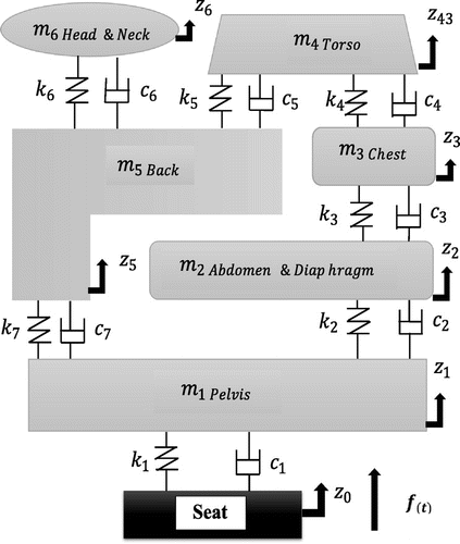
The model of automotive passenger body is shown to investigate vibration transmissibility and transmitted accelerations for different segments of the human body due to two road various profiles excitation and speeds. For this purpose, a lumped parameter 6-DoF biomechanical model is suggested with six concentrated masses by using the springs and dampers for connecting to each other. The proposed model is considered to calculate biodynamic responses or evaluation criteria for biodynamics of seated human, consisted of Apparent Mass (APM), Driving Point Mechanical Impedance (DPMI) and Seat-To-Head Transmissibility (STHT) for the sitting position of the human body without backrest support in vertical direction. For more information about evaluation criteria see Bai’s work (Bai et al., Citation2017) and ISO 5982-2001.
The 6-DoF model is illustrated in Figure .
For adaptation the presented model the experimental data by Boileau and Rakheja (Citation1988) have been used. The mentioned experimental data include: Seat-To-Head-Transmissibility (STHT), Driving Point Mechanical Impedance (DPMI) and Apparent Mass (APM) responses. The dynamic equations for the suggested model in the time domain are as follows:(1)
(1)
(2)
(2)
(3)
(3)
(4)
(4)
(5)
(5)
(6)
(6)
where in the above equations m
i
denotes the mass and z
i
, is displacement, velocity and acceleration, respectively. Also, c
i
and k
i
represented damping and stiffness coefficients for i = 1, 2, 3 …, 6 respectively. z
0,
represented seat displacement and velocity, respectively, which are considered as system inputs. If the initial conditions are assumed to be zero then Equations (1)–(6) in the frequency domain according to Equation (7):
(7)
(7)
where in the above equation represents applied force to passenger body system. Hence, as can be written:
(8)
(8)
(9)
(9)
(10)
(10)
(11)
(11)
(12)
(12)
(13)
(13)
The equations of motion for this vibrational human body system are written in the frequency domain in the matrix as:(14)
(14)
Replacing S by jω in above matrix, vibration transmissibility seat to head in frequency domain is:(15)
(15)
And driving point mechanical impedance is obtained as:(16)
(16)
Also, human body apparent mass response is illustrated as Equation (17):(17)
(17)
Errors’ rate in biomechanical responses consist of STHT, DPMI and APM in a sitting position are defined as:(18)
(18)
(19)
(19)
(20)
(20)
where in the above equations N is the number of points in the frequency range. Although by increasing the number of points the precision become higher, but for too large values the accuracy doesn’t show much increase. The stimulation frequency of f (1) = 0.5 to f (N) = 20 Hz is defined (Boileau, Wu, & Rakheja, Citation1998). In order to optimize the objective functions, the following equation will be used simultaneously:
(21)
(21)
where , i = 1, 2, 3 are the minimum errors when the model is optimized with respect to the parameters individually. At this point, having determined the
, the error for all three items will be minimized at the same time with the use of Equation (21). The values obtained for the model in this section will be the final coefficients for the 6-DoF model.
Using Genetic Algorithms (GA) in MATLAB parameters of the masses, stiffness and damping of the 6-DoF model so that the minimum function is obtained. The parameters of GA method are listed in Table .
Table 1. GA parameters
The only condition in this issue is that the total mass of the human body is equal to 60.98 kg. Because the total mass of the model should be equal to the mean value for masses from the experimental data.
2.2. Vehicle modeling and various vehicle speeds and road profiles effects analysis
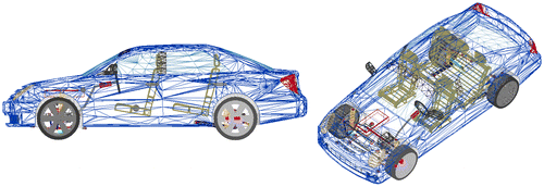
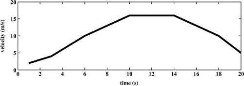
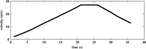
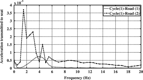
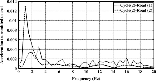
In this part, vehicle condition and road tests on two different profiles are explained at various speeds with two driving cycles. The sedan-FWD vehicle is considered in the quite similar situation to real car, which is demonstrated in Figure . It is mentioned that weighting vehicle model is 1792.2 kg. The present simulated vehicle first, is moved on polyline and roughness roads profiles for various speeds in the first driving cycle, part of the first driving cycle is shown in Figure . Next, the present simulated vehicle is moved on polyline and roughness roads profiles at various speeds in the second driving cycle, part of the second driving cycle is illustrated in Figure . At each stage the accelerations which are induced by road excitations which applied to the automotive passenger seat in a vertical direction are calculated. Further, the vibration transmissibility and transmitted acceleration are evaluated for all human body segments in vertical direction and in frequency range of 0 to 20 Hz, because the ideal range for vibration analysis of the human body is from 0.5 to 20 Hz (Boileau et al., Citation1998). The applied accelerations to the passenger’s seat due to the road profiles with two driving cycles including roughness (road-1) and polyline (road-2) profiles can be observed in Figures and .
3. Results and discussion
In this part, the results of the models that were presented in the previous section, will be discussed. The 6-DoF biomechanical model is created based on the obtained results by Boileau and Rakheja (Citation1988). While the experimental data includes: Seat-To-Head Transmissibility, Driving Point Mechanical Impedance and Apparent Mass responses. The mentioned experimental data is illustrated in Table .
Table 2. The obtained experimental data by Boileau and Rakheja (Citation1988)
To achieve the parameters of 6-DoF biomechanical model above, experimental results can be used. The only linear requirement that must be met during the multi-objective optimization is the summation of the masses. Respect to experimental data (Boileau & Rakheja, Citation1988) it should be equal to 60.98 kg in accordance with the following equation:(22)
(22)
In Table , the optimal parameters of the proposed model is displayed using genetic algorithm.
Table 3. The optimal parameters for a 6-DoF model
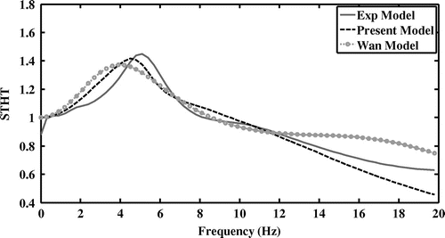
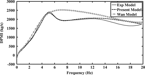
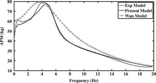
Sayers (Citation1988), have done a comparison between twelve biomechanical models of 1 to 11 degrees of freedom and concluded that the Wan model (Wan & Schimmels, Citation1995), had the best fit with the Boileau experimental data. In order to a better compare for the presented model results with the experimental results the Wan model results are added in Figures –.
In Figure , the STHT responses are shown in the frequency domain 0 to 20 Hz. As indicated in Figure , laboratory results has the highest value for transmissibility in 5 Hz, while in the current model this maximum value for transmissibility is occurred in the same frequency with a little difference in the value of transmissibility while for Wan model this difference is not appeared. As the adaptation is observed from Figure , it can be said that the presented model is in a great improvement with Seat-To-Head transmissibility over previous models. In Figure , the Driving Point Mechanical Impedance responses with the unit kg/s in the frequency domain 0 to 20 Hz, are illustrated.
As shown in Figure , laboratory results for the DPMI responses had a peak in 5 Hz, while for the presented model the peak occurred in 5.5 Hz, but for the Wan model this peak happened in 7 Hz. Also, in all the frequency domain, a good match between the proposed model and experimental results have been established. While, this adjustment is occurred for the Wan model only at frequencies below 5 Hz.
The Apparent Mass responses are illustrated in Figure , with the unit of kg in the frequency range of 0 to 20 Hz. Last diagrams are shown a good agreement between experimental results and presented model with higher quality in compare with the Wan model.
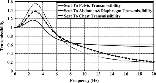
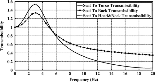
As regards, the vibration transmissibility function is related to comfort feeling and since, is presented the exact model of the human body, can be calculated the vibration transmissibility for all human body segments. The vibration transmissibility for all human body parts consisted of m 1 to m 3 (pelvis, abdomen and diaphragm, chest), and m 4 to m 6 (torso, back, head and neck) are shown in Figures and respectively.
As can be observed from the vibration transmissibility values in different body segments. The vibration transmissibility rate in Chest and Torso has the highest value among all segments, while this amount in Pelvis for the contact with seat has the lowest value.
To show present model accuracy in comparison with Wan’s model, error criteria has calculated and presented in Table . There 4 error criteria has been used.
Table 4. Error criteria comparison between Wan’s model and 6-DOF present model
For Sum of Square Error (SSE), Root Mean Square Error (RMSE) and Mean Absolute Percentage Error (MAPE) error criteria, the lowest value is the best and for Coefficient of Determination (R 2) the highest is better. So it can be concluded from the Table that the present model is better fitted to the experimental data (Taylor, Citation1982).
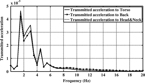
The simulated vehicle is moved on the roughness (road-1) and polyline (road-2) roads profiles in the first driving cycle and the vertical accelerations are calculated in both cases. These accelerations are applied to the vehicle passenger model with 6-DoF in order to evaluate transmitted acceleration for individual segments for m 1 to m 6 in vertical direction, which are shown in Figures –, respectively.
Figure 12. Transmitted accelerations to the human body for three body segments including pelvis, abdomen/diaphragm and chest of road-1 excitation in the first driving cycle.
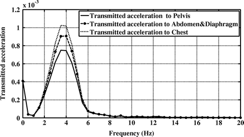
Figure 13. Transmitted accelerations to the human body for three body segments including torso, back and head/neck of road-1 excitation in the first driving cycle.
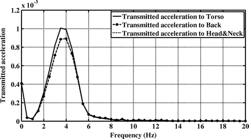
Figure 14. Transmitted accelerations to the human body for three body segments including pelvis, abdomen/diaphragm and chest of road-2 excitation in the first driving cycle.
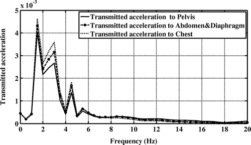
Figure 15. Transmitted accelerations to the human body for three body segments including torso, back and head/neck of road-2 excitation in the first driving cycle.
The maximum values for transmitted acceleration and the corresponding frequency for each body segments of road-1 excitation in the first driving cycle, which are shown in Figures and , are presented Table .
Table 5. The transmitted accelerations results for all body segments respect to road-1 excitation in the first driving cycle
Also, the maximum values for transmitted acceleration and the corresponding frequency for each body segments of road-2 excitation in the first driving cycle, which are shown in Figures and , are presented Table .
Table 6. The transmitted accelerations results for all body segments respect to road-2 excitation in the first driving cycle
The simulated vehicle is moved on the roughness (road-1) and polyline (road-2) roads profiles in the second driving cycle and the vertical accelerations are measured in both cases. The transmitted acceleration results for all human body segments consisted of m 1 to m 6 in vertical direction are shown in Figures – respectively.
Figure 16. Transmitted accelerations to the human body for three body segments including pelvis, abdomen/diaphragm and chest of road-1 excitation in the second driving cycle.
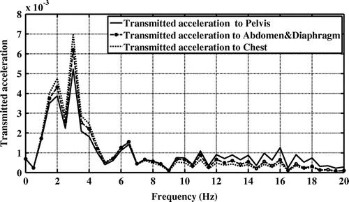
Figure 17. Transmitted accelerations to the human body for three body segments including torso, back and head/neck of road-1 excitation in the second driving cycle.
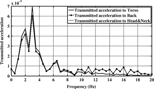
Figure 18. Transmitted accelerations to the human body for three body segments including pelvis, abdomen/diaphragm and chest of road-2 excitation in the second driving cycle.
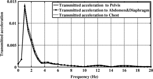
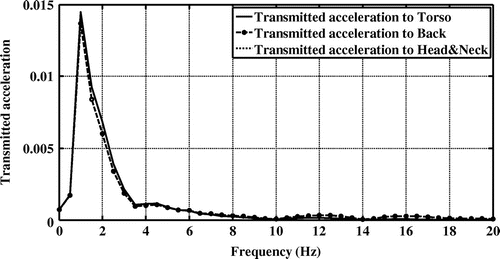
Figure 19. Transmitted accelerations to the human body for three body segments including torso, back and head/neck of road-2 excitation in the second driving cycle.
The maximum values for transmitted acceleration and the corresponding frequency for each body segments of road-1 excitation which are shown in Figures and , are presented Table .
Table 7. The transmitted acceleration results for all body segments respect to road-1 excitation in the second driving cycle
Also, the maximum values for transmitted acceleration and the corresponding frequency for each body segments of road-2 excitation in the second driving cycle, which are shown in Figures and , are presented Table .
Table 8. The transmitted acceleration results for all body segments respect to road-2 excitation in the second driving cycle
Finally, according to the above figures, it can be said that the higher value of transmitted accelerations for the human body segments is occurred in the range of frequencies between 1 Hz to 5 Hz. Moreover, the human body physics amplify the acceleration in range about 3–4 Hz. So vehicle designer shall choose an approach to avoid magnifying excitation in this range.
4. Conclusion
In this study, the automotive passenger body is modeled by a 6-DoF lumped parameter model without backrest. And model parameters are using Genetic Algorithms with the least error compare to laboratory results. With the help of human body model are extracted the biomechanical responses and the vibration transmissibility for all human body parts. Furthermore, the sedan-FWD vehicle model is developed with ADAMS/CAR software and by using the simulated vehicle four tests are investigated on two roads including roughness and polyline roads profiles that are known as ADAMS/CAR software profiles. The mentioned vehicle is moved on two roads profiles with two various driving cycle and the transmitted accelerations to under the passenger’s seat due to roads excitation are calculated. By using calculated accelerations, the transmitted accelerations for all human body segments are investigated for all states. As a result, it can be said first, the vibrations transmissibility rate in Chest and Torso has the highest value among all segments, while this amount in Pelvis for the contact with seat has the lowest value. Next, the transmitted acceleration to the vehicle cabin in a specific driving cycle by reducing vehicle speed is decreased. In order to increase comfort of automotive passenger, the transmitted acceleration to the vehicle cabin must be reduced as much as possible. For this purpose, the vibration and energy absorbing foams in seat design or a shock absorber system can be used under passenger’s seat.
Funding
The authors received no direct funding for this research.
Cover image
Source: Authors.
Additional information
Notes on contributors
Somaye Jamali Shakhlavi
Somaye Jamali Shakhlavi is a PhD student in School of Mechanical Engineering at Iran University of Science and Technology. She has 10 published papers in the conferences and journals.
Javad Marzbanrad
Javad Marzbanrad received PhD degree in Mechanical Engineering from Tarbiat Modarres University, Tehran, Iran, in 2001. Now he is an associate professor in School of Automotive Engineering at Iran University of Science and Technology. His research interests are Automotive, Control and Vibration and Solid Mechanics. He has more than 280 published papers in the conferences and journals. He also published eight books in mechanical fields.
Vahid Tavoosi
Vahid Tavoosi is a PhD candidate in the School of Automotive Engineering at Iran University of Science and Technology.
References
- Nagamani, M. S. (2017). Minimization of human body responses due to automobile vibrations in quarter car and half car models using PID controller. SSRG International Journal of Mechanical Engineering (SSRG-IJME) .
- Afkar, A. , Marzbanrad, J. , & Amirirad, Y. (2015, February 1). Modeling and semi active vertical vibration control of a GA optimized 7DoF driver model using an MR damper in a seat suspension system. Journal of Vibration Engineering and Technologies , 3 (1), 37–47.
- Allen, G. (1978). A critical look at biomechanical modeling in relation to specifications for human tolerance of vibration and shock. AGARD Conference Proceedings No. 253 , Paper A25-5, Paris, France, 6–10.
- Bai, X.-X. , Xu, S.-X. , Cheng, W. , & Qian, L.-J. (2017). On 4-degree-of-freedom biodynamic models of seated occupants: Lumped-parameter modeling. Journal of Sound and Vibration , 402 , 122–141.10.1016/j.jsv.2017.05.018
- Blood, R. P. , Ploger, J. D. , Yost, M. G. , Ching, R. P. , & Johnson, P. W. (2010). Whole body vibration exposures in metropolitan bus drivers: A comparison of three seats. Journal of Sound and Vibration , 329 , 109–120.10.1016/j.jsv.2009.08.030
- Boileau, P. E. , & Rakheja, S. (1988). Whole-body vertical biodynamic response characteristics of the seated vehicle driver: Measurement and model development. International Journal of Industrial Ergonomics , 22 , 449–472.
- Boileau, P. E. , Wu, X. , & Rakheja, S. (1998). Definition of a range of idealized values to characterize seated body biodynamic response under vertical vibration. Journal of Sound and Vibration , 215 (4), 841–862.10.1006/jsvi.1998.1674
- Gillespie, T. D. , Karamihas, S. M. , Sayers, M. W. , Nasim, M. A. , Hansen, W. , Ehsan, N. , & Cebon, D. (1993). Effects of heavy-vehicle characteristics on pavement response and performance (p. 126). NCHRP Report 353. Washington, DC: Transportation Research Board.
- Mansfield, N. , Sammonds, G. , & Nguyen, L. (2015). Driver discomfort in vehicle seats – Effect of changing road conditions and seat foam composition. Applied Ergonomics , 50 , 153–159.10.1016/j.apergo.2015.03.010
- Marzbanrad, J. , & Afkar, A. (2013). A biomechanical model as a seated human body for calculation of vertical vibration transmissibility using a genetic algorithm. Journal of Mechanics in Medicine and Biology , 13 (4), 1350053.10.1142/S021951941350053X
- Muksian, R. , & Nash, C. D. (1976). On frequency-dependent damping coefficients in lumped parameter models of human beings. Journal of Biomechanics , 9 , 339–342.10.1016/0021-9290(76)90055-5
- Nawayseh, N. , & Griffin, M. J. (2009). A model of the vertical apparent mass and the fore-and-aft cross-axis apparent mass of the human body during vertical whole-body vibration. Journal of Sound and Vibration , 319 , 719–730.10.1016/j.jsv.2008.05.030
- Patil, M. K. , & Palanichamy, M. S. (1988). A mathematical model of tractor-occupant system with a new seat suspension for minimization of vibration response. Applied Mathematical Modelling , 12 , 63–71.10.1016/0307-904X(88)90024-8
- Patil, M. K. , Palanichamy, M. S. , & Ghista, D. N. (1977). Dynamic response of human body seated on a tractor and effectiveness of suspension systems. SAE Paper , 770932 , 755–792.
- Patil, M. K. , Palanichamy, M. S. , & Ghista, D. N. (1978). Man-tractor system dynamics: Toward a better suspension system for human ride comfort. Journal of Biomechanics , 11 , 397–406.10.1016/0021-9290(78)90074-X
- Rahmatalla, S. , & DeShaw, J. (2011). Effective seat-to-head transmissibility in whole-body vibration: Effects of posture and arm position. Journal of Sound and Vibration , 330 , 6277–6286.10.1016/j.jsv.2011.07.034
- Sayers, M. W. (1988, April). Dynamic terrain inputs to predict structural integrity of ground vehicles. UMTRI Report No. UMTRI-88-16, 114 pp.
- Sayers, M. W. , & Karamihas, S. M. (1996, January). Interpretation of road roughness profile data. Final Report SPR-2 (159), Federal Highway Administration, Contract No. DTFH 61-92-C00143.
- Suggs, C. W. , Abrams, C. F. , & Stikeleather, L. F. (1969). Application of a damped spring-mass human vibration simulator in vibration testing of vehicle seats. Journal of Ergonomics , 12 , 79–90.10.1080/00140136908931030
- Taylor, J. R. (1982). An introduction to error analysis: The study of uncertainties in physical measurements . Mill Valley, CA: University Science Books.
- Wagner, J. , & Liu, X. (2000). An active vibration isolation system for vehicle seats. SAE Paper , 275 , 7–18.
- Wan, Y. , & Schimmels, J. M. (1995). A simple model that captures the essential dynamics of a seated human exposed to whole body vibration. Advances in Bioengineering, ASME, and BED , 31 , 333–334.

