 ?Mathematical formulae have been encoded as MathML and are displayed in this HTML version using MathJax in order to improve their display. Uncheck the box to turn MathJax off. This feature requires Javascript. Click on a formula to zoom.
Abstract
A numerical simulation for an optimal operating condition of a hollow fiber reverse osmosis desalination system has been carried out by utilizing the membrane transport model based on the porous media theory. The validity of the present numerical simulation has been examined by comparing permeate salinity and flow rate obtained by the present method with the available experimental data. The three-dimensional numerical computations have revealed individual velocity and concentration distributions for brine, permeate and membrane phases in a hollow fiber reverse osmosis module containing a feeder core tube. Moreover, it has been found that optimal feed brine pressure exists in order to receive the maximum permeate flow rate under the same pumping power. The present numerical methods is useful to design a hollow fiber desalination module and find the operating conditions of a desalination system.
Public Interest Statement
The novelty of this work is establishing of numerical simulation method based on membrane transport model. It makes us to obtain 3d distributions of velocity and concentration fields for brine, permeate and membrane phases in the reverse osmosis module containing a feeder core tube. These visual distributions would help engineers to understand the desalination system, the reverse osmosis phenomenon and concentration polarization. The present numerical method would be useful to design a hollow fiber desalination module. Moreover, this numerical simulation revealed the existence of the optimal feed brine pressure in order to receive the maximum permeate flow rate under the same pumping power. This result would contribute to reduce energy consumption of reverse osmosis system for sustainable use of water resources.
1. Introduction
Reverse Osmosis (RO) is one of the familiar technology for middle and large size desalination plants since the high quality fresh water can be created from sea water and brackish water with high efficiency as compared with other processes such as an evaporation process (Fritzmann, Löwenberg, Wintgens, & Melin, Citation2007). Membrane materials (Fritzmann et al., Citation2007; Kang & Cao, Citation2012; Lee, Arnot, & Mattia, Citation2011; Wang et al., Citation2014), module designs (Fritzmann et al., Citation2007; Peñate & Rodríguez, Citation2012) and mass transfer phenomena including concentration polarization (Wang et al., Citation2014) etc. have been studied for sustainable use of water resources. In the studies of mass transport, various membrane transport models, namely, solution-diffusion model (Kimura & Sourirajan, Citation1967), friction-concentration- polarization model (Sekino, Citation1993, Citation1995) and Spiegler–Kedem model (Spiegler & Kedem, Citation1966) were proposed for mathematically describing transport phenomena through membranes. An appropriate model has to be chosen in order to design the modules and determine the operating conditions by numerical simulation.
Gupta (Citation1985, Citation1987), Ohya, Nakajima, Takagi, Kagawa, and Negishi (Citation1977), Evangelista and Jonsson (Citation1990), Tweddle, Thayer, Matsuura, and Fu-Hung (Citation1980) adopted the solution-diffusion model to investigate tubular, plate-and-frame and spiral modules as well as radial flow hollow fiber modules. The friction-concentration-polarization model was adopted by Al-Bastaki and Abbas (Citation1999, Citation2000), Kumano, Sekino, Matsui, Fujiwara, and Fujiwara (Citation2008), Marcovecchio, Scenna, and Aguirre (Citation2010) and Chatterjee, Ahluwalia, Senthilmurugan, and Gupta (Citation2004) for estimating desalination performance of actual modules. The Spiegler-Kedem model, which introduced reflection coefficient in addition to the solution-diffusion model, is believed to be more accurate for describing transport phenomena through membranes with polarization, as demonstrated by Murthy and Gupta (Citation1994, Citation1998). Recently, according to Anqi, Alrehili, Usta, and Oztekin (Citation2016), the effect of arrangement of hollow fibers on mass transfer in the reverse osmosis system was investigated by microscopic numerical simulation within several hollow fibers. On the other hand, Marcovecchio, Scenna, and Aguirre (Citation2010) proposed a macroscopic numerical simulation method for the whole module. However, it is hard to accurately estimate macroscopic mass transfer in the whole module while accurately predicting the mass transfer in micro-fields of hollow fiber size. Nakayama and Sano (Citation2013), on the other hand, proposed the membrane transport model based on the volumeaveraging theory (Ingham & Pop, Citation2005; Nakayama, Citation1995; Nakayama & Kuwahara, Citation2007; Nakayama, Kuwahara, & Kodama, Citation2006; Nield & Bejan, Citation2013; Pop & Ingham, Citation2001; Vadasz, Citation2008; Vafai, Citation2005, Citation2010) in order to overcome the problem explained above. However, the numerical simulation based on the membrane transport model has never established so that three-dimensional individual velocity and concentration fields for all phases (i.e. brine, permeate and membrane phases) has not captured yet.
In this paper, the three-dimensional numerical computations based on the membrane transport model introduced by Nakayama and Sano (Citation2013) are proposed to determine an optimum operating condition in a hollow fiber reverse osmosis system. The present numerical simulation reveals individual velocity and concentration fields for all phases within a hollow fiber reverse osmosis module. In this study, firstly, permeate salinity and flow rate obtained from the present method are compared against available experimental data so as to examine the validity of the present numerical method. Subsequently, through a series of calculations, an optimal feed brine pressure is estimated for receiving maximum permeate flow rate under the same pumping power. The present numerical simulation reveals that an optimal pressure of the feed brine exists to receive maximum permeate flow rate for given pumping power.
2. Three-concentration model for hollow fiber membrane systems
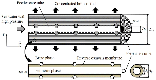
A hollow fiber reverse osmosis module is illustrated in Figure , in which hollow fibers are packed in the module. Fresh water can be created permeating through the reverse osmosis membrane from sea water or brackish water with high pressure. (See previous paper (Nakayama & Sano, Citation2013), if detailed information about module is needed). In the membrane transport model for a hollow fiber reverse osmosis module, individual velocities and salt concentrations are defined in three phases, namely, brine, permeate and membrane phases. Assigning the subscripts, b, p and m to the brine phase, permeate phase and membrane phase, respectively, the following relations can be found for the volumefractions ɛ
b
, ɛ
p
ɛ
m
, the specific area of the brine compartment a
b
and that of the permeate compartment a
p
:(1a)
(1a)
(1b)
(1b)
(1c)
(1c)
(2a)
(2a)
(2b)
(2b)
Note that N is the number of hollow fibers while A is the effective cross-sectional area of the reverse osmosis module. The membrane thickness, the inner and outer diameters of the hollow fiber are indicated by t m , d p and d b = d p + 2t m , respectively.
A set of the volumeaveraged governing equations can be written for the reverse osmosis desalination phenomena, as follows:
Brine phase:(3)
(3)
(4)
(4)
(5)
(5)
Permeate phase:(6)
(6)
(7)
(7)
(8)
(8)
Membrane phase:(9)
(9)
where(10)
(10)
Equations (3)–(5) describe the continuity, momentum and mass balance equations for brine phase, while Equations (6)–(8) describe these equations for permeate phase, respectively. Moreover, Equation (9) is mass balance equation for membrane phase, where the intrinsic average is defined as
(11)
(11)
where the volumeV
f
(f = b, p, m) is the volumespace, which f phase occupies within the total local control volumearranged hollow fibers V. As defined in Equation (10), ω is the ultrafiltration volumerate per unit volume, which is the product of the specific area of the membrane surface ab and the total permeate volumeflux J
V
through the membrane. The membrane is characterized in terms of three parameters, namely, the hydraulic permeability L
P
, the solute permeability h
m
and the reflection coefficient σ. Moreover, the osmotic pressure is given by , where i, R = 8341 J/(kg kmol K), M and
are the number of ions for ionized solutes (i.e. Vant Hoff factor), ideal gas constant, molecular weight of solute and temperature, respectively. In this study, these three-dimensional tonsorial macroscopic governing Equations (3)–(10) are exploited for three-dimensional numerical calculations.
As carrying out three dimensional numerical calculations based on Equations (3)–(10), the permeability tensor is given by(13)
(13)
The axial permeability component within brine phase may be evaluated using the hydraulic diameter concept as(14)
(14)
while the transverse components may be estimated according to Kuwahara, Nakayama, and Koyama (Citation1996) as(15)
(15)
Inertial coefficient within the brine phase is given by(16)
(16)
The axial dispersion diffusivity component may be estimated following Kuwahara et al. (Citation1996)(17a)
(17a)
(17b)
(17b)
where Peclet number Pe
D
is defined as follow.(17c)
(17c)
The transverse dispersion diffusivity components and
are usually as small as 1/20 of the axial dispersion counterpart (Yang & Nakayama, Citation2010). The mass transfer coefficient h
b
between the brine and membrane may be estimated according to Sekino (Citation1993):
(18)
(18)
The total mass transfer resistance between the membrane and permeate, on the other hand, is approximated by1/a
b
h
m
as in Equation (8), since the mass transfer resistance between permeate and membrane is much higher than it of permeate phase:(19)
(19)
The axial permeability component within the permeate phase may be given as(20)
(20)
The axial permeability component can be estimated by Equation (20) with assumption of fully-developed laminar flow in hollow fiber channels, while the transverse components
may virtually be set to zero. The dispersion diffusivity component for the permeate phase may be ignorable following Nakayama et al. (Citation2006).
3. Three-dimensional numerical computations
In this study, the numerical integrations of foregoing governing equations were carried out using the finite volumemethod with SIMPLE algorithm (Nakayama, Citation1995). Sano, Horibe, Haruki, Nagase, and Nakayama (Citation2014), Sano, Nishimura, and Nagase (Citation2014) introduced the combined velocity vector for calculating mass transport within the dialysis membrane in which flow rate is varied by ultrafiltration. In this study, the continuity Equations (3) and (6) contain ω, it would not be straightforward to formulate the pressure correction equation based on SIMPLE. In order to overcome this problem, we shall adopt the combined velocity vector u as follows:(21)
(21)
Upon substituting Equation (21) into continuity and momentum equations for brine phase, we obtain(22)
(22)
(23)
(23)
A series of numerical simulations have been carried out based on foregoing governing Equations (5), (7), (8), (9), (21), (22) and (23).
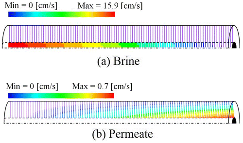
A numerical model based on Toyobo Hollosep module HR8355 is shown in Figure , in which fibers wound around the feeder core tube for the fed brine. In this numerical simulation, velocity field of brine phase in a feeder core tube is solved to reveal velocity distribution at entrance of the hollow fiber bundle by adopting the values ε = 1, namely, K → ∞, b = 0 in Equation (23). Note that permeate phase does not exist in a feed core tube (i.e. u p = 0). Therefore, Equation (23) reaches to Navier–Stokes equation under these conditions, so that velocity field in a whole module can be solved with a flow rate conservation condition on the boundary between a feeder core tube and a hollow fiber bundle. Boundary conditions for brine phase can be set the given velocity at an inlet feeder core tube, free outflow condition at the outlet from a hollow fiber bundle, and non-slip condition on the other boundaries, respectively. In permeate phase, on the other hand, velocity should be zero at left side of a hollow fiber bundle in Figure since hollow fibers are sealed at the end of Toyobo Hollosep module HR8355. Therefore, when given free outflow condition at right side in the hollow fibers, permeate flows toward right side in the hollow fibers as shown in Figure .
On the other hand, concentration fields for all phases are calculated in the region filled with hollow fibers. Salt concentration can be given based on experimental value on the boundary between a feeder core tube and a hollow fiber bundle. Free outflow condition is set to the outlets of brine and permeate phases. Salt flux has to be zero on the other boundaries. In this study, an effective length is introduced so as to treat with wound fibers as arranged in parallel in the module, when the velocity field of permeate component is solved in the present numerical simulation.(22)
(22)
The specifications of Toyobo Hollosep module and its operating conditions (Sekino, Citation1993; Spiegler & Kedem, Citation1966) are listed in Table based on the experiment by Sekino (Citation1993). In all calculations, it was confirmed that the conservation law is satisfied by integrating velocity and concentration over the boundary of a module.
Table 1. Specifications of Toyobo Hollosep module HR8355 and its operating conditions
4. Results and discussions
In Figure , cross-sectional velocity fields in brine and permeate phases are illustrated in terms of local velocity vectors, when the inlet brine volumeflow rate, pressure and salt concentration are set to , P
feed
= 5.5 MPa and c
feed
= 35 kg/m3. Note that computational region of brine phase is whole module consisted of a feeder core tube and a hollow fiber bundle, while computational region of permeate phases is a hollow fiber bundle. As can be seen from Figure (a), it is found that the brine particles are fed from the inlet of the feeder core tube and uniformly pass into the bundles of hollow fibers. It is because that the brine particles are pressed by the uniform hydraulic pressure since the hydraulic permeability of a hollow fiber bundle for brine phase is small. The concentrated brine flows out radially to the outer side of the fiber bundle. On the other hand, permeate penetrates through the membrane due to the hydraulic pressure and osmotic pressure so that its flow rate increases toward the outlet of hollow fibers. As can be seen from Figure (b), the flow rate of permeate increases toward the center from the outside of a module since the hydraulic pressure of brine is high at the core side.
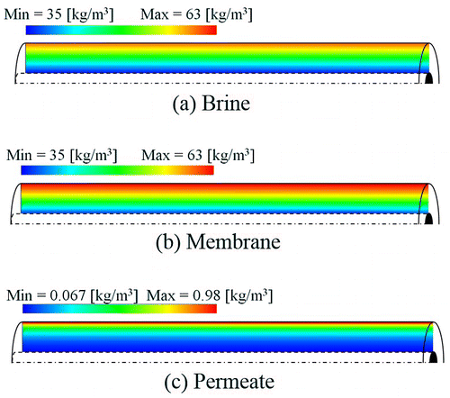
The individual concentration fields for brine, permeate and membrane phases are illustrated in Figure . The concentration of brine phase increases radially as permeate penetrates through the membranes. Brine is concentrated due to the decrease of the solvent. On the other hand, salt concentration of membrane phase is higher than it of brine phase since the concentration polarization takes place within the membrane. Therefore, the present numerical simulation can describe the concentration polarization phenomena. Concentrations of membrane and permeate phases increase along with the condensation of the brine salinity. Through the numerical calculation, it is found that the diameter of a hollow fiber bundle is important to receive permeate with high flow rate and low salt concentration from a reverse osmosis system. Moreover, prediction of concentration polarization at surface of membranes is also important since it affect to the flow rate and concentration fields of all phases.
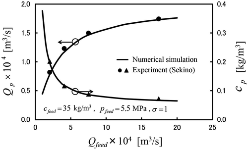
In order to examine the validity of the present numerical simulation, Figure shows the permeate flow rate Q p and concentration of the produced permeate c p against the feed brine flow rate Q feed under the condition of c feed = 35 kg/m3. All dots plotted in the figure are referred to experimental results carried by Sekino (Citation1993) with same module and same conditions. It is found that permeate flow rate increases with feed brine flow rate, while concentration of permeate decreases against feed brine flow rate since the concentration of brine phase can be kept low by applied high feed flow rate. On the other hand, low flow rate and high salt concentration for permeate phase is obtained in low feed flow rate since concentration of brine phase is easily increases with penetration of permeate through the membranes. Note that the present results agree well with the available experimental data presented by Sekino (Citation1993). It indicates the validity of the present numerical estimation based on the membrane transport model. In this study, the effect of fouling on the performance in the reverse osmosis desalination system is not considered since this study is the first step for numerical simulation based on membrane transport model. We believe that performance developing by time can be predicted by applying the fouling model (Shirazi, Lin, Doshi, Agarwal, & Rao, Citation2006). In this study, we shall try to estimate the optimal operating condition of initial state in a reverse osmosis system by the present numerical simulation.
5. Optimum operating condition
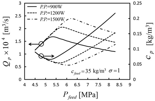
The present numerical simulation based on Equations (3)–(10) enables one to determine the optimal operating condition in terms of the permeate salinity, permeate flow rate for given pumping power. In this study, pumping power PP is defined as follows.(23)
(23)
where and P
atm
are brine pressure at outlet of a module and atmospheric pressure. In Figure , permeate flow rate Q
p
and concentration of the produced permeate c
p
are shown against the feed brine pressure under c
feed
= 35 kg/m3, PP = 900, 1200 and 1500 W. As can be seen from Figure , there exists an optimum feed brine pressure so as to receive the maximum permeate flow rate for given pumping power. When increasing the feed brine pressure, the hydraulic pressure difference between brine and permeate phases increases so that permeate flow rate increases with the feed brine pressure. However, the feed brine flow rate decreases with the feed brine pressure under the same pumping power condition, so that permeate flow rate decreases with the feed brine pressure. On the other hand, permeate concentration decreases with increasing solvent, while permeate concentration increases with the condensation of the brine. Thus, the maximum permeate flow rate and minimum permeate concentration exist under the same pumping power. Moreover it is found that permeate concentration reaches at minimum value in around same pressure in which permeate flow rate reaches at the maximum value. As usually, maximum permeate flow rate and minimum permeate concentration are desired in an operation of a hollow fiber reverse osmosis desalination system. Thus, optimum operating conditions are estimated as 5.3, 5.8 and 6.2 MPa under the pumping powers 900, 1200 and 1500 W.
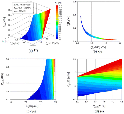
Figure (a) shows 3D graph associated with permeate flow rateQ p , concentration of the produced permeatec p and feed brine pressure P feed for given several pumping powers. Moreover, Figure (b)–(d) indicate relationships between Q p − c p , c p − P feed and P feed − Q p , respectively. The relationships among permeate flow rate, concentration of the produced permeate, feed brine pressure and pumping power explaining above are confirmed from Figure . We can choose the best feed brine pressure in order to receive maximum permeate flow rate in case of any pumping power by utilizing Figure . The present numerical methods based on the membrane transport model can be useful to design a hollow fiber desalination module and find the operating conditions of a desalination system.
6. Conclusions
The three-dimensional numerical computations revealed individual concentration fields within a hollow fiber reverse osmosis module by utilizing the membrane transport model based on the volumeaveraging theory. A series of calculations revealed that an optimal pressure of feed brine exists in order to receive the maximum permeate flow rate for same pumping power. It was found that the optimum operating conditions are estimated as 5.3, 5.8 and 6.2 MPa under the pumping powers 900, 1200 and 1500 W in Toyobo Hollosep module HR8355. The present numerical methods can be useful to design a hollow fiber desalination module and find the operating conditions of a desalination system.
| Nomenclature | ||
| A int | = | interface between the fluid and membrane phases (m2) |
| a b,p | = | specific surface area (1/m) |
| b b,p | = | Forchheimer coefficient (1/m) |
| c | = | salt concentration (kg/m3) |
| d p,b | = | inner and outer diameters of the hollow fiber (m) |
| D i,o | = | inner and outer diameters of the fiber bundle (m) |
| D b | = | diffusivity of the brine (m2/s) |
| h b | = | mass transfer coefficient of the brine (shell side) (m/s) |
| h m | = | solute permeability of the membrane (m/s) |
| i | = | Vant Hoff factor |
| J V | = | permeate volumeflux through the membrane (m/s) |
| K b,p | = | permeability (m2) |
| L | = | length of the module (m) |
| L * | = | effective length of the module (m) |
| L p | = | hydraulic permeability of the membrane (m/(s Pa)) |
| M | = | molecular weight of the solute (–) |
| n i | = | unit vector pointing outward from the fluid side to membrane side (–) |
| p | = | pressure (Pa) |
| Pe D | = | Peclet number (–) |
| Q feed | = | feed brine flow rate (m3/s) |
| Q p | = | permeate flow rate (m3/s) |
| r | = | radial coordinate (m) |
| R | = | universal gas constant (J/(kg kmol K)) |
| R in | = | intrinsic rejection (–) |
| S | = | total membrane surface area (m2) |
| t m | = | membrane thickness (m) |
|
| = | temperature of the feed brine (K) |
| u i | = | velocity vector (m/s) |
| V | = | representative elementary volume(m3) |
| W | = | number of wound of hollow fibers (–) |
| x | = | axial coordinate (m) |
| Greek symbols | ||
| ɛ b,p,m | = | volumefraction (–) |
| μ | = | viscosity (Pa s) |
| ρ | = | density (kg/m3) |
| σ | = | reflection coefficient (–) |
| ω | = | permeate volumeflow rate per unit volume(1/s) |
| Special symbols | ||
|
| = | deviation from intrinsic average |
|
| = | intrinsic average |
| Subscripts and superscripts | ||
| b | = | brine |
| p | = | permeate |
| m | = | membrane |
| feed | = | feed brine |
Funding
This work has been generously supported by JSPS Grants-in-Aid for Scientific Researches [grant number 26740049].
Additional information
Notes on contributors
Y. Sano
My studies have focused on heat and mass transfer within complicated structures. Especially, in recent years, I have been attracted to mass transfer through membranes, namely, reverse osmosis membrane, ion exchange membrane and dialysis membrane. In order to accurately predict mass transport phenomena within a complicated structure, accurately prediction about the boundary layer on the surface of the structure is required. However, a large number of grids are required to predict the boundary layer associated with mass transport in a whole device by numerical simulation. Therefore, the method for connecting micro and macro transport phenomena is necessary required. In mass transfer through membranes, there exists some scales associated with mass transfer, namely, holes on membrane, membrane itself and devise consisted of membrane. I believe that deriving a unified theoretical method for treating mass transfer through membrane will contribute to develop industry.
References
- Al-Bastaki, N. M. , & Abbas, A. (1999). Modeling an industrial reverse osmosis unit. Desalination , 126 , 33–39.10.1016/S0011-9164(99)00152-6
- Al-Bastaki, N. M. , & Abbas, A. (2000). Predicting the performance of RO membranes. Desalination , 132 , 181–187.10.1016/S0011-9164(00)00147-8
- Anqi, A. E. , Alrehili, M. , Usta, M. , & Oztekin, A. (2016). Numerical analysis of hollow fiber membranes for desalination. Desalination , 398 , 39–51.10.1016/j.desal.2016.07.019
- Chatterjee, A. , Ahluwalia, A. , Senthilmurugan, S. , & Gupta, S. K. (2004). Modeling of a radial flow hollow fiber module and estimation of model parameters using numerical techniques. Journal of Membrane Science , 236 , 1–16.10.1016/j.memsci.2004.01.006
- Evangelista, F. , & Jonsson, G. (1990). Explicit design of hollow fiber reverse osmosis systems. Proceedings of ICOM , 2 , 1081–1085.
- Fritzmann, C. , Löwenberg, J. , Wintgens, T. , & Melin, T. (2007). State-of-the-art of reverse osmosis desalination. Desalination , 216 , 1–76.10.1016/j.desal.2006.12.009
- Gupta, S. K. (1985). Analytical design equations for reverse osmosis systems. Industrial & Engineering Chemistry Process Design and Development , 24 , 1240–1244.10.1021/i200031a057
- Gupta, S. K. (1987). Design and analysis of a radial-flow hollow-fiber reverse-osmosis system. Industrial & Engineering Chemistry Research , 26 , 2319–2323.10.1021/ie00071a024
- Ingham, D. B. , & Pop, I. (2005). Transport phenomena in porous media (Vol. III). Oxford: Elsevier.
- Kang, G. , & Cao, Y. (2012). Development of antifouling reverse osmosis membranes for water treatment: A review. Water Research , 46 , 584–600.
- Kimura, S. , & Sourirajan, S. (1967). Analysis of data in reverse osmosis with porous cellulose acetate membranes used. AIChE Journal , 13 , 497–503.10.1002/(ISSN)1547-5905
- Kumano, A. , Sekino, M. , Matsui, Y. , Fujiwara, N. , & Fujiwara, N. (2008). Study of mass transfer characteristics for a hollow fiber reverse osmosis module. Journal of Membrane Science , 324 , 136–141.10.1016/j.memsci.2008.07.011
- Kuwahara, F. , Nakayama, A. , & Koyama, H. (1996). A numerical study of thermal dispersion in porous media. Journal of Heat Transfer , 118 , 756–761.10.1115/1.2822696
- Lee, K. P. , Arnot, T. C. , & Mattia, D. (2011). A review of reverse osmosis membrane materials for desalination-Development to date and future potential. Journal of Membrane Science , 370 , 1–22.10.1016/j.memsci.2010.12.036
- Marcovecchio, M. G. , Scenna, N. J. , & Aguirre, P. A. (2010). Improvements of a hollow fiber reverse osmosis desalination model: Analysis of numerical results. Chemical Engineering Research and Design , 88 , 789–802.10.1016/j.cherd.2009.12.003
- Murthy, Z. V. P. , & Gupta, S. K. (1994). Sodium cyanide separation and parameter estimation for reverse osmosis thin film composite polyamide membrane. Journal of Membrane Science , 154 , 89–103.
- Murthy, Z. V. P. , & Gupta, S. K. (1998). Thin film composite polyamide membrane parameters estimation for phenol-water system by reverse osmosis. Separation Science Technology , 33 , 2541–2557.10.1080/01496399808545318
- Nakayama, A. (1995). PC-aided numerical heat transfer and convective flow . Boca Raton: CRC Press.
- Nakayama, A. , & Kuwahara, F. (2007). A general bioheat transfer model based on the theory of porous media. International Journal of Heat and Mass Transfer , 51 , 3190–3199.
- Nakayama, A. , Kuwahara, F. , & Kodama, Y. (2006). An equation for thermal dispersion flux transport and its mathematical modelling for heat and fluid flow in a porous medium. Journal of Fluid Mechanics , 563 , 81–96.10.1017/S0022112006001078
- Nakayama, A. , & Sano, Y. (2013). An application of the Sano-Nakayama membrane transport model in hollow fiber reverse osmosis desalination systems. Desalination , 331 , 95–102.10.1016/j.desal.2012.11.012
- Nield, D. A. , & Bejan, A. (2013). Convection in porous media (4th ed.). New York, NY : Springer.10.1007/978-1-4614-5541-7
- Ohya, H. , Nakajima, H. , Takagi, K. , Kagawa, S. , & Negishi, Y. (1977). An analysis of reverse osmotic characteristics of B-9 hollow fiber module. Desalination , 21 , 257–274.10.1016/S0011-9164(00)88245-4
- Peñate, B. , & Rodríguez, L. G. (2012). Current trends and future prospects in the design of seawater reverse osmosis desalination technology. Desalination , 284 , 1–8.
- Pop, I. , & Ingham, D. B. (2001). Convective heat transfer: Mathematical and computational modeling of viscous fluids and porous media . Oxford: Pergamon.
- Sano, Y. , Horibe, A. , Haruki, N. , Nagase, K. , & Nakayama, A . (2014). Numerical approach for optimal design of a hollow fiber dialyzer system. Open Journal of Heat, Mass and Momentum Transfer , 2 : 58–69.10.12966/hmmt.10.01.2014
- Sano, Y. , Nishimura, T. , & Nagase, K . (2014). A porous media approach for hollow fiber transport phenomena. Open Journal of Heat, Mass and Momentum Transfer , 2 : 11–27.10.12966/hmmt.04.01.2014
- Sekino, M. (1993). Precise analytical model of hollow fiber reverse osmosis modules. Journal of Membrane Science , 85 , 241–252.10.1016/0376-7388(93)85278-5
- Sekino, M. (1995). Study of an analytical model for hollow fiber reverse osmosis module systems. Desalination , 100 , 85–97.10.1016/0011-9164(96)00010-0
- Shirazi, S. , Lin, C. J. , Doshi, S. , Agarwal, S. , & Rao, P. (2006). Camprison of fouling mechanism by CaSO4 and CaHPO4 on nanofiltration mechanism. Separation and Purification Technology , 41 , 2861–2882.
- Spiegler, K. S. , & Kedem, O. (1966). Thermodynamics of hyperfiltration (reverse osmosis): Criteria for efficient membranes. Desalination , 1 , 311–326.10.1016/S0011-9164(00)80018-1
- Tweddle, T. A. , Thayer, W. L. , Matsuura, T. , & Fu-Hung, H. (1980). Specification of commercial reverse osmosis modules and predictability of their performance for water treatment applications. Desalination , 32 , 181–198.10.1016/S0011-9164(00)86019-1
- Vadasz, P. (2008). Emerging topics in heat and mass transfer in porous media . New York, NY : Springer.10.1007/978-1-4020-8178-1
- Vafai, K. (2005). Handbook of porous media (2nd ed.). New York, NY : Taylor and Francis.
- Vafai, K. . (2010). Porous media . CRC Press.10.1201/9781420065428
- Wang, J. , Dlamini, D. S. , Mishra, A. K. , Pendergast, M. T. M. , Wong, M. C. Y. , Mamba, B. B. , … Hoek, E. M. V. (2014). A critical review of transport through osmotic membranes. Journal of Membrane Science , 454 , 516–537.10.1016/j.memsci.2013.12.034
- Yang, C. , & Nakayama, A. (2010). A synthesis of tortuosity and dispersion in effective thermal conductivity of porous media. International Journal of Heat and Mass Transfer , 53 (15–16), 3222–3230.10.1016/j.ijheatmasstransfer.2010.03.004

