
Abstract
Design and manufacturing strategies for custom orthotic insole shoes for patients with diabetes are presented in this paper. The computer-aided reverse engineering system (CARESystem) was applied for minimizing file errors generated by scanning a patient’s foot. The digital data imaging and communication of medicine (DICOM) images were used for designing complex insole orthotics. The DICOM images obtained by HandySCANN 700TM were then converted into a stereo lithography (STL) file (triangle-based data) format. The color map generated by VX Element and Geomagic software yielded an accurate and smooth STL data file of the patient’s foot. A solid 3D model of orthotic shoe s (insole and outsole) was prepared using the curve-based surface modeling method (CBS model). The error of an image found in the 3D mesh STL file was then edited and smoothed, prior to the 3D prototype products being processed by 3D printers. The prototype of an orthotic shoe insole was fabricated by an adaptive manufacturing machine, the 3D printer EDEN350. Comparative analysis of dimensional data for the insole and outsole revealed that the average size of deviation was less than 1 mm (0.0135–0.0209 mm). Therefore, this method is highly promising to deliver custom orthotics with improved size, dimensional accuracy, and comfort.
PUBLIC INTEREST STATEMENT
Nowadays, custom orthotic shoes are promising methods for the treatment of foot pain and lower limb pathology. However, difficulties in the design and fabrication of such footwear are usually reported due to variations in orthotic device design and fabrication. The best method for obtaining optimally designed custom foot orthotics is the use of computer-aided design (CAD), which involves a low design time and low manufacturing cost. The main aim of the present study is to develop a beneficial and innovative method with the computer-aided reverse engineering system (CARESystem) to produce insole and outsole prototypes that fit the shape of the feet of a patient with diabetes. The stages of this research are initiated by foot scans with HandySCANN 700TM, followed by STL files that are verified with VX Element. The findings can be a guide for constructing custom insole orthotics with low production cost and a product with improved quality.
1. Introduction
The human foot frequently suffers from plantar pressure distribution during physical activities such as standing, playing, and walking. This condition may lead to risk of injury that can be minimized by wearing personal footwear with optimal fit and comfort. The human foot has complex geometry (Bernabéu et al., Citation2013). People may have different foot shapes; some may suffer from foot deformities caused by diabetes. This disease has the highest potential to damage a person’s feet (Qiu, Teo, Yan, & Lei, Citation2011; Salles & Gyi, Citation2012; Ye et al., Citation2008). In 2009, the World Health Organization (WHO) described that at least 289 million people have diabetes and this number may increase to 438 million people by 2030. These patients may suffer from foot deformities such as pronation, metatarsalgia, flat feet, neuroma, plantar fasciitis, and arch pain (Anggoro, Bawono, Policharpus, Jamari, & Bayuseno, Citation2017; The American Orthopaedic Foot & Ankle Society, Citation2016; Vicenzino, Citation2004; Yao, Citation2005). These deformities often lead to pain and discomfort in the feet when people wear shoes or sandals. Foot ulceration is a common complication of diabetes (Yao, Citation2005). Many other factors may promote foot ulceration, such as elevated temperature/humidity within a shoe, increased in-shoe plantar pressure (pressure under the foot) (Salles & Gyi, Citation2012; Ye et al., Citation2008), and increased shear movement between the foot and shoe. If the diabetic foot is untreated, it can cause an infection and the patient must undergo total or partial foot amputation (Bernabéu et al., Citation2013).
The foot ulceration of a patient with diabetes may be healed using custom-made foot orthoses (Bernabéu et al., Citation2013) and proper fitting footwear can help prevent ulcerations and amputations. Foot orthotics can be implemented for pain relief to increase the heel cushion, correct flexible deformity, increase foot stability, and/or prevent skin breakdowns (Salles & Gyi, Citation2012). Custom orthotic shoes are promising methods for foot pain treatment and lower limb pathology; they allow an individualized prescription for designing personalized footwear with good fit and comfort (Ye et al., Citation2008).
Much attention has been paid to the development of custom foot orthotics in the manufacture of shoes and sandals (Ye et al., Citation2008). However, difficulties in the design and fabrication of such footwear are usually reported due to variations in orthotic device design and fabrication. Different aspects of design such as insole geometry (Qiu et al., Citation2011), outsole profile/stiffness (Mogeni, Duraijajah, & Gobee, Citation2014; Oancea, Ivan, & Pescaru, Citation2013), and shoe lacing contributing to foot ulceration (Pescaru, Oancea, & Badan, Citation2012), must be based on prescription and non-prescription foot orthoses.
The danger of trauma due to ulceration can be minimized by designing appropriate footwear for a specific foot shape and function; such measures can be conducted based on an individualized prescription of a patient with diabetes (Chapman et al., Citation2013; Uccioli & Giacomozzi, Citation2012). Custom orthotic products are frequently manually made in the handicraft industry in which technicians with high skill and experience are needed (Anggoro et al., Citation2017; Xia, Citation2014). This approach is a time-consuming process and the resulting product may exhibit low accuracy and poor surface finish, thereby leading to significant discomfort in the feet of the patient (Qiu et al., Citation2011).
The best method for obtaining optimally designed custom foot orthotics is the use of computer-aided design (CAD) that involves a low design time and low manufacturing cost (Mogeni et al., Citation2014). With the availability of CAD packages, reverse engineering (RE) has emerged as a practical method to obtain an object without data engineering drawings, documentation, and computer models (Oancea et al., Citation2013; Pescaru et al., Citation2012). The use of 3D CAD shortens the design time in RE and minimizes costs involved during manufacturing (Chapman et al., Citation2013). The obtained input data of the scanning process contain a detailed and accurate model. Additionally, RE was successfully adopted for fabricating insole shoe orthotics made from Eva rubber for normal people’s feet and subsequently manufactured by subtractive manufacturing machines (Rolland model MDX 40R). This process provided the best-fitted insole product (Anggoro, Bawono, Wijayanto, Jamari, & Bayuseno, Citation2016; Manmadhachary, Ravi Kumar, & Krishnanand, Citation2016) that was quite similar to the surface contours of the human foot obtained from scanning. However, the typical error on the surface quality of the insole shoe orthotics was due to differences in the size of the physical model and the prototype, or the lost data of the inaccurate scanning results, or CAD output.
In contrast to the subtractive manufacturing process, rapid prototyping (RP) is a layer-by-layer manufacturing technology commonly employed for medical models (Ay et al., Citation2013; Huang et al., Citation2010; Karatas & Toy, Citation2014; Othman, Citation2012). The RP model of human anatomy can be generated from high-resolution digital images such as computed tomography, magnetic resonance imaging, and any other medical scanning processes (Santolaria, Jiménez, Rada, & Loscos, Citation2014). The acquired medical data set from the medical scanner is subsequently segmented into 2D pictures. These pictures are usually kept in digital imagery and communication in medicine (DICOM) file format (voxels), which can be acquired in a 3D biomedical computer-aided design (Bio-CAD) model. The Bio-CAD model can be subsequently exported into a stereo lithography (STL) file to fabricate the RP medical model (Ameddah & Assas, Citation2011; Nguyen, Vo, Le, & Lou, Citation2015). However, the STL file format has some dimensional errors, especially in the RE model of a human figure. The quality of STL files for 3D imaging data can be improved.
The quality of STL file imaging data for RP medical models was further improved via accurate DICOM images (Ay et al., Citation2013; Lorensen & Cline, Citation1987). The images were converted into an STL file (triangle-based data) format, which was subsequently used for the manufacture of medical models via RP technologies. Given that the inaccuracy and rough surface of the RP model was often generated due to the errors in STL file, a fast Fourier transform method was proposed to improve the surface contour data points, which generated a surface and STL file simultaneously by the delay triangulation method. This novel combination method provided accuracy and smoothness to the generated STL file compared to the initial STL file. This study proposes that the STL files of the RP insole model may be changed into the triangulation angle using the algorithm for trimming and hole-filling operations.
Advanced design methodologies in terms of the computer-aided reverse engineering system (CARESystem) have been proposed to ease the acquisition of design knowledge and creative ideas through reverse innovative design (RID). RID can cover a wide range of 3D digital design usages such as 3D digitization, 3D CAD and computer-aided industrial design (CAID), RE, computer-aided engineering (CAE) analysis, and RP (Anggoro, Bawono, Policharpus, et al., Citation2017, Anggoro, Bawono, Wijayanto, et al., Citation2016; Bernabéu et al., Citation2013; Manmadhachary et al., Citation2016; Othman, Citation2012; Xia, Citation2014). Recent studies have demonstrated the capability of RID in designing innovative footwear products (Anggoro, Bawono, Policharpus, et al., Citation2017, Anggoro, Bawono, Wijayanto, et al., Citation2016; Bernabéu et al., Citation2013; Othman, Citation2012; Xia, Citation2014) using the 3D image of a patient’s foot and manufacturing orthotic shoes. RID can develop and deliver a product with various designs (Bernabéu et al., Citation2013) and it allows adjustment of a personalized shoe product. This systematic approach optimizes an existing design and reduces the error rate in manufacturing products. Systematic studies based on the RID methodology to design customized shoes for patients with diabetes are limited. Thus, the design and improved manufacturing process for orthotic insole shoes (OIS) based on the RE model of patients with diabetes is crucial (Uccioli & Giacomozzi, Citation2012). The design of specific diabetic footwear for increased comfort requires automated systems such as the CARESystem.
The main aim of the present study is to develop a beneficial and innovative method with the CARESystem to produce insole and outsole prototypes fitting the foot shape of a patient with diabetes. The stages of this research are initiated by foot scans with HandySCANN 700TM, followed by STL files verified with VX Element. PowerSHAPE 2016 software received a fixed 3D CAD foot model with an error of less than 1 mm. The prototype orthotic models are manufactured by the 3D printer machine EDEN350V. The findings can be a guide for constructing custom insole orthotics with low production cost and improved quality.
2. Materials and methods
2.1. Physical model of 3D digitizing and mesh processing
Two female participants (50–75 years old) were selected for this research. Both patients were selected because of their long history of diabetes (around 10 years) and the pain they experienced when wearing normal sandals or shoes. Similar to previous research (Anggoro et al., Citation2016; Othman, Citation2012; Ye et al., Citation2008), the RID was adopted to design the OIS; the design process involves an integrated digital design methodology incorporating digitizing, modeling with shape parameters and product definition, and analyzing for CAE-based product optimization and RP models (Ye et al., Citation2008). In the present work, a 3D data acquisition process was developed by a physical model and mesh processing using non-contact 3D scans by HandySCAN 700TM equipped with VX Element software. Based on this sterolithography concept, this scanning tool produces output data in the form of an STL file, which is insensitive to vibration, and it does not adhere to the object. White light, or laser-enabled rapid data processing (in the range of 5–10 min), and similar lasers can produce accuracy levels of upward to 5 µm. The 3D scanner is equipped with two cameras and seven types of lasers that can retrieve the data objects and reach a small gap in images.
HandySCAN 700TM was chosen because it has seven intersecting laser beams that can speed up high-precision shooting [0.030 mm (0.0012 in)]. This instrument delivers a single-function laser that can be employed to arrive at the infantry of a gap on the object of a complicated and complex surface contour. It is also equipped with a laser beam for the x–y value with an accuracy of up to 30 µm and a z-value of 5 µm.
The 3D CAD data of an RE foot were initially verified prior to further processing. An indispensable component of the 3D mesh foot was marked from the ball of the foot area to the heel (the component that is in direct touch with the insole). Verification was conducted via color mapping (see Figure ). Verification of the object enabled the distribution of the size difference between the data of the scanning results in the form of the 3D mesh and results of the RE were differentiated using color symbols.
Figure 1. Ball of foot as indicated within the blue line of the 3D mesh foot area.
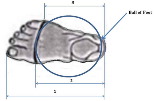
The color map was analyzed by comparing the 3D CAD surface with the 3D mesh STL with the same orientation. Comparative analysis between the VX Element 5 and PowerSHAPE 2016 features was also performed. The sample points on the two images being compared were obtained, calculated for the gap between the dots, and displayed in shades of red to blue. VX Element 5 software provided 3D scanning to capture data directly (real time) from the 3D scanner of HandySCAN 700TM and data were displayed on the computer screen. This software consisted of modules from Element VX, VX Inspect, and VX models. VX Element 5 retrieved data and performed 3D scanning to check whether the mesh processing of 3D solid models fit the foot.
The custom insoles required highly accurate molding, plumbing, and machining tools. Comparative analysis via VX Element 5 could verify the output of 3D scanning. If the average deviation was less than 1 mm, or 50% of the deviation was less than 1 mm, then the data were accepted for further processing. Thus, the data of the STL file were fixed and used for subsequent CBS (curve-based modeling) to produce the insole and outsole of orthotic shoes. The results of the color mapping in VX Element 5 are presented in Table .
Table 1. Color mapping analysis and verification of scanning from 3D mesh to 3D CAD model of insole and outsole shoe orthotics for (a) patient 1 and (b) patient 2
2.2. Modeling from the 3D mesh foot to the 3D solid of insole and outsole of orthotic shoes
The 3D solid model of the patient’s foot in VX Element 5 was then required to establish a wireframe curve insole starting from oblique processing to 3D surface editing for an existing curve. Three modeling strategies of RE are widely known (Bernabéu et al., Citation2013; Ye et al., Citation2008): automatic surface modeling, feature-based solid modeling, and CBS modeling. CBS modeling was selected in this work because it could reconstruct the 3D model of the OIS with high precision and accuracy. This scheme has been successfully adopted to manufacture OIS for people with normal feet and foot deformities (Anggoro, Bawono, Policharpus, et al., Citation2017, Anggoro, Bawono, Wijayanto, et al., Citation2016; Manmadhachary et al., Citation2016; Othman, Citation2012). CBS modeling and the smart features in PowerSHAPE 2016 resulted in the 3D surface form using the created curves and provided the reconstructed surface with high accuracy. Stages of CBS modeling in PowerSHAPE 2016 included (a) mesh importing and pre-processes, (b) rewiring, (c) repointing, building, and verifying a 3D surface to a solid foot with a solid doctor, (d) a 3D solid model of the foot from the mesh, (e) oblique processing, (f) foot wireframe, (g) support wire, (h) repoint wireframe curve, (i) wire reconstruction, (j) generating surface, (k) surface curve editing, and (l) 3D solid iso diabetes (Wang, Wang, & Lin, Citation2010; Yoo, Citation2011). Results of the 3D solid model of OIS for the patients with diabetes showed a variety of width tolerances. A new optimal design of an OIS with 2:00- mm width tolerance of a 3D solid was established according to the previous OIS made by the RP model (Anggoro et al., Citation2016; Deng & Lin, Citation2014; Othman, Citation2012). Similarly, the outsole section was analyzed, but a wide gap of 0.75 mm was found between the insole and outsole.
2.3. Manufacturing process of the RP model
A pair of RP OIS models was fabricated by adaptive manufacturing technology with 3D printers Object EDEN 350 V, which contains the engine of 3D printers by Stratasys released with a tray of 350 mm × 350 mm × 200 mm. This machine uses PolyJet technology, which allows the material expenditure with a thick layer of up to 16 µm. It has an accuracy rate of 0.1–0.3 mm depending on the geometry, orientation, and size of the product.
Two kinds of materials and two supports of 3.6 kg were labeled as VeroBlue material, VeroWhitePlus, VeroBlack, TangoGray, TangoBlack, TangoBlackPlus, FullCure720 Transparent, and FullCure Support. The material prototype of the customized insole orthotics was assigned as OIS VeroWhitePlus RGD835. The plastic material was one of the materials suggested by Stratatys in the operation of Eden 350V 3D printing. The material properties of the polymer are presented as follows: tensile strength of 50–65 MPa, elongation at break of 10%–25%, modulus of elasticity of 2000–3000 MPa, flexural strength of 75–110 MPa, flexural modulus of 2200–3200 MPa, heat deflection temperature of 45°C–50°C at 1.82 MPa, water absorption of 1.1%–1.5%, shore hardness of 83 Scale-86 D, Rockwell hardness Scale M of 73–76, 1:17 to 1:18 polymerized density (g/cm3), and ash contents of 0:23% to 0:26% (VeroGray, VeroWhitePlus) and 0:01% to 0:02% (VeroBlackPlus) (Karatas & Toy, Citation2014).
3. Results
The multiple images of the 3D foot models resulting from output scanning, verification of the VX Element, and prototype OIS products are given in Figures –. The form of the 3D mesh foot (Figure ) was subsequently justified for insole and outsole orthotic models. VX software-Element 5 was directly connected to the computer and Handyscan 700TM could greatly optimize the 3D solid model of RE (Figure ). Table presents results of the standard deviation for both pairs of legs of the patients with an average deviation of less than 1 mm. The output file of RE was then converted into a pair of insoles and outsoles using CBS modeling (Bernabéu et al., Citation2013) with a variation in width tolerance. The optimal width tolerance (Anggoro et al., Citation2016; Othman, Citation2012) employed in this study provided a good fit with the patient’s feet on the second insole, of which assembly with wide legs of 2.00 mm tolerance is shown in Figure .
Figure 2. The 3D mesh of the STL file for the feet of (a) patient no. 1 and (b) patient no. 2.
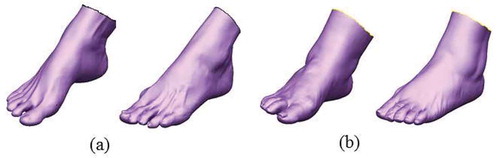
Figure 3. Output file of the RE foot patient in STL file format.
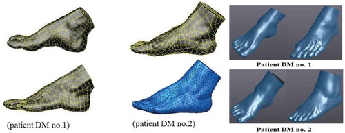
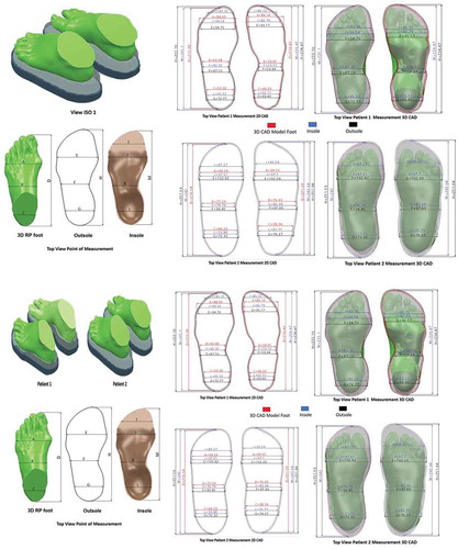
Figure 4. Top view and new isometric 3D design of the foot assembly a insole for two diabetic patients.
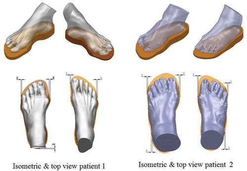
Figure 5. Top views of the RP model prototype assembly for two diabetic patients.
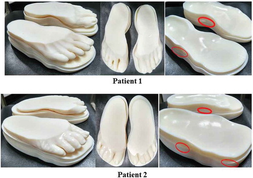
Figure 6. Prototype of the RP model for insole shoe orthotics.
The RP models of the insole, outsole, and foot of each patient were formed in terms of all solid 3D images of the insole, outsole, and foot; the models were verified by the open source system software Autodesk Netfabb 2017. Such software significantly improved and optimized the STL file before being placed into the 3D printer machine. This optimized STL file was mainly directed to failure reduction when the file was inserted into the machine/tool (EDEN 350V). The manufactured products of RP models are shown in Figures and .
The RP models of the OIS product were then verified for precise dimensional size and suitability of fit between the physical model and the 3D CAD models using a vernier caliper with 0.01 mm tolerance. The RP models were measured by determining area dimensions in the CAD drawings (the measured point) given in Figure . The results of the dimensional verification of RP models between the CAD drawings and OIS prototype products show an average size difference of less than 0.5 mm (Tables and ). Relatively small deviation in dimensional size was found for prototypes that were deviated by more than 1 mm. Thus, the CAD drawings of the scanning results and color map of a prototype displayed a good fit with a dimensional model. The results of the prototype were confirmed in accordance with existing CAD drawings.
Table 2. Measured dimensions of CAD models and prototype models of OIS for patient 2
Table 3. Measured dimensions of CAD models and prototype models of OIS for patient 1
Figure 7. Area of foot measurement points: insole and outsole orthotics.
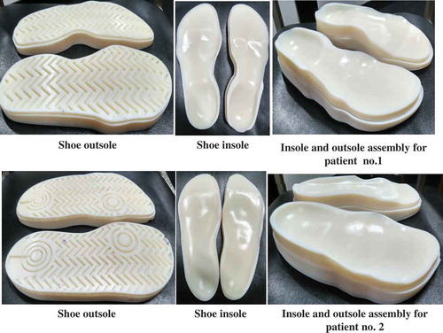
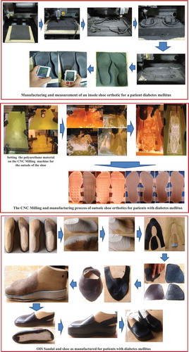
It the present work, the fabrication of the OIS has been manufactured using CARESystem based on a CNC machine to create insoles, outsoles, and shoe lasts as shown in Figures –, respectively. Furthermore, these shoe parts are manually assembled by the shoemaker to generate the shoe as shown in Figure . It should be noted that the EVA (ethylene–vinyl–acetate) foam material with a hardness of 30–40 HRC is used for the insole, while the material of polyurethane (PU) is adopted for the outsole. For the actual shoe last, Ebalta wood is chosen. The fabrication of the OIS based on the CARESystem takes a manufacturing time of 8–10 days. Of course, this time is much lower than that based on the conventional method (up to 2 months). A more in-depth detail of the fabrication process for OIS using the CARESystem is shown in Figure .
Figure 8. Insole of shoes manufactured for two patients.
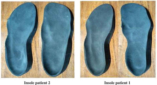
Figure 9. Outsole of shoes manufactured for two patients.
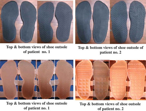
Figure 10. Shoe lasts of shoes manufactured for two patients.
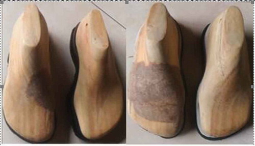
Figure 11. Shoes with orthotic insoles as manufactured.
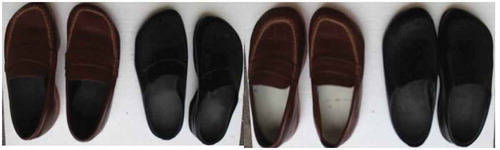
Figure 12. Steps of fabricating an orthotic insole shoe using the developed system CARES.
It the present study, in order to obtain the benefits of an insole shoe developed to respond to the satisfaction of diabetic patients regarding shoe quality, a simple survey questionnaire has been administered. This survey is addressed to the two patients of different ages and body weights. The content of the questionnaire, depicted in Table , contains the measurement of the level of importance, satisfaction, and expectations desired by both DM patients dealing with shoe quality. It should be noted that the OIS products have been used by the two patients for about 6 weeks. The result of the questionnaire is reflected in Table . It is found that the value of satisfaction is around 3.9 and 4.0 (very satisfied), respectively, for patients 1 and 2. For the expectations, the value is around 3.7 and 3.8 (very satisfied), respectively, for patients 1 and 2. It indicates that the satisfaction level of each user is higher than the level of expectation for both patients. In other words, the patients are very satisfied with the comfort and performance of the shoes.
Table 4. The content of the questionnaire for diabetic patients
Table 5. The results of the questionnaire given to diabetic patients
4. Discussion
This study demonstrated an excellent method for the design of an OIS product using a 3D mesh foot obtained from 3D scanning. An infrared laser beam from HandySCANN 700TM was applied on the foot surface for at least 10 min. The results of this 3D scanning are in the form of 3D mesh STL files. The 3D mesh STL, or triangle mesh, is a set of surface dots that form a small triangle. This small triangle can be linked to form a custom geometry of an object. Triangle mesh data is more appropriate for RE because the shaped surface can be outfitted with the foot in terms of cloud points instead of dots. This procedure allows the RE to be fast because it does not need to be converted into a point cloud of STL. 3D scanning was performed to obtain the data for insoles from the base of the foot up to the ankle area. The foot area is an important part because it is in direct contact with the footwear. Arches and other parts of the foot surface were required to form 3D insole orthotics that can be obtained from 3D scanning. The results of the 3D mesh STL file were consistent with the original shape of the foot. Correspondingly, accuracy below the tolerance limit of 1 mm was achieved in the present study. This important file was employed in subsequent machining with the CNC machine for both insole and outsole products with materials such as EVA rubber foam and PU.
The CAD technology displayed certain limitations for image processing with the organic contours of the foot shape of the patients with high-risk diabetes (Janisse & Coleman, Citation2008; Lavery, Armstrong, Wunderlich, Tredwell, & Boulton, Citation2003). This condition resulted in frequent errors when editing foot images using the solid feature. CAD software failed to extract the surface of the foot, while 3D mesh did so perfectly with the features of shrink wrap. Nevertheless, the benefits of CAD may be explored for feature comparison analysis between the 3D mesh and 3D CAD insoles. The results of this analysis will allow researchers to decide whether the RE process can be continued or not.
Additionally, the function of VX Element 5 can simplify the analysis data of RE with PowerSHAPE2016. The 3D mesh can be changed by automatic clicking on surface features into the 3D surface of the mesh so that it can be read and analyzed in PowerSHAPE 2016. VX Element 5 has also been reported to process the RE model of patients with foot deformities (Anggoro, Bawono, Policharpus, et al., Citation2017, Anggoro, Bawono, Wijayanto, et al., Citation2016; Manmadhachary et al., Citation2016; Othman, Citation2012; Vicenzino, Citation2004). In the present research, the 3D surface of the mesh was extracted to a solid by this software that yielded an average deviation of less than 1 mm. Therefore, the program enabled the input of optimal surface mesh data for the manufacturing process.
The color maps revealed that the results of RE were green, which indicates a small deviation. The improvement in the leg of patient 1 produced an average deviation of 0.1395833 to 0.0937500 mm with an error range of −0.3756 to 0.6413 in the left and right feet of −0.3707 mm to 0.5926 mm (Table ). The color map for patient 2 indicated an average deviation of 0.1326389 mm up to 0.1451389 mm with an error range in the left foot of −1.6146 to 0.6066 mm and that of the right foot of −0.7644 to 0.5640 mm (Table ). The results of RE were appropriate and further processed in an RP machine using the EDEN350V 3D printer to obtain optimal new OIS products. The mean deviation of RE results in Table was less than 1 mm, which indicates that the accuracy of the image described in this paper was high. Automatic surfacing results were in accordance with the scanned form of physical models.
Once 3D models of the fixed foot were obtained, the insole and outsole of orthotic shoes were designed based on CBS modeling (Anggoro, Bawono, Policharpus, et al., Citation2017, Anggoro, Bawono, Wijayanto, et al., Citation2016; Bernabéu et al., Citation2013; Othman, Citation2012; Xia, Citation2014). The 3D model of the new insole and outsole orthotic shoes was successfully produced by CBS modeling. CAE analysis with a width tolerance of 0.75 mm frequently provides the optimal design of an insole product for patients with diabetes (Anggoro et al., Citation2017; Othman, Citation2012). In this study, the optimal design was constructed using the EDEN350V 3D printer to yield prototypes of a foot, insole, and outsole of special customized OIS.
The verification of size dimensions in the image STL file, 3D CAD models, and prototype RP models was conducted similarly to the previous RP medical models (Santolaria et al., Citation2014). The outcomes of this study equally demonstrated a dimensional error of less than 1 mm, whereas the mean error in the initial STL models was in the range of 0.38–0.16 mm (Santolaria et al., Citation2014). The mean error of the STL smooth model showed tolerant values of 0.201 and 0.268 mm for patient number 2 and 0.254 and 0.214 mm for patient number 1. These results indicate that the application of the CARESystem in the design of OIS delivered quality custom orthotics similar to the medical models (Santolaria et al., Citation2014). The similarity lies in the average value of the dimensional error generated in the STL smooth image model of the RP model. Accordingly, the results of this study can be applied in shoes and sandal industries for producing inexpensive custom insole and outsole orthotics for patients with diabetes (Armstrong, Peters, Athanasiou, & Lavery, Citation1998; Brown, Wertsch, Harris, Klein, & Janisse, Citation2004; Bus, Ulbrecht, & Cavanagh, Citation2004). The CARESystem strategy has potential in design applications for patients with foot deformities such as flat foot, high-heel syndrome, Morton’s neuroma, and metatarsalgia (Cavanagh et al., Citation2002; Germania, Mandolini, Mengoni, Nester, & Raffaeli, Citation2012; Schie, Ulbrecht, Becker, & Cavanagh, Citation2000).
The 3D printing construction is proven to have better performance than the manual insole shoe making process. It is found that 3D printing has a lower manufacturing time. In addition, the manufactured shoes fit the feet better when compared to the manufacture by conventional methods.
Further research will be focused on the number of patients, as well as the foot deformities, to produce a more comprehensive database of insole shoes dealing with the best design solutions and a shorter manufacturing time. In addition, this finding can improve the response time between the doctor and the patient. In the future, it will be necessary to make a collaboration between the patient, doctor, technical measurement taker, designer, and the insole shoe maker.
5. Conclusions
CARESystem was applied to provide customized special orthotic products that are specifically designed and manufactured for patients with high-risk diabetes mellitus. OIS products exhibited precise surface contours and dimensional fit of the feet of the patients, and they provided a good level of comfort and reduced pain in patients. In the future, CARESystem can be used to design custom shoe orthotics for the feet of disabled patients (flat feet, high-heel syndrome, Morton’s neuroma syndrome, metatarsalgia, and other foot deformities). This system is expected to resolve the design and manufacturing problems faced by sandal and shoe industries for developing customized OIS products.
Competing interests
The authors declare no competing interests.
Acknowledgements
The authors would like to gratefully thank Mrs. Stefani as the Head of the Engineering Department, PT. Trimitra Wisesa Abadi, Mr. V. Ariyono, as Chairman of the Department of Industrial Engineering and Laboratory Production Process, Industrial Engineering Program, Faculty of Industrial Technology, University of Atma Jaya Yogyakarta, and the Tribology Laboratory of the Department of Mechanical Engineering, University of Diponegoro in Semarang, that already provided full support in the form of CAD, CAM, CAE 3D HandySCAN, and 3D Printer infrastructure during the design and manufacturing process.
Additional information
Funding
Notes on contributors
Paulus Wisnu Anggoro
P.W. Anggoro is a PhD candidate in the Mechanical Engineering Department of the University of Diponegoro, Indonesia. His research interest includes product design based on Reverse Innovative Design Engineering with additive and subtractive manufacturing technology.
M. Tauviqirrahman
M. Tauviqirrahman obtained a doctoral degree from the Laboratory for Surface Technology and Tribology, University of Twente, the Netherlands.
J. Jamari
J. Jamari received a doctoral degree from the Laboratory for Surface Technology and Tribology, University of Twente, the Netherlands.
A. P. Bayuseno
Athanasius P. Bayuseno is a professor in material science and engineering and Head of the Graduate Doctoral Program in the Mechanical Engineering Department of Diponegoro University, Indonesia. His research interest includes dealing with Ceramics, as well as Materials Science and Engineering.
B. Bawono
B. Bawono is a PhD candidate in the Mechanical Engineering Department of the University of Diponegoro, Indonesia. His research interest includes numerical analysis with statistical tools.
M. M. Avelina
M. M. Avelina received a BS degree in engineering from the University of Atma Jaya, Yogyakarta, Indonesia. His major research interest includes product design.
Related Research Data
References
- Ameddah, H. , & Assas, M. (2011). Bio-CAD reverse engineering of free-form surfaces by planar contours. Computer Aided Design and Application , 8(1), 37–42. doi:10.3722/cadaps.2011.37-42
- Anggoro, P. W. , Bawono, B. , Wijayanto, A. , Jamari, J. , & Bayuseno, A. P. (2016). Parameter optimatizion of strategies at CNC end Milling Machine Roland Modela MDX 40R CAM against surface roughness made insoles shoe orthotic EVA Rubber Foam. International Journal of Mechatronic & Mechanical Engineering , 16(4), 96–107.
- Anggoro, P.W. , Saputra, E. , Tauviqirrahman, M. , Jamari, J. , & Bayuseno, A. P. (2017). A 3-dimensional finite element analysis of the insole shoe orthotic for foot deformities. International Journal of Applied Engineering Research , 12(15), 5254 –5260. ISSN: 0973-4562
- Armstrong, D. G. , Peters, E. J. , Athanasiou, K. A. , & Lavery, L. A. (1998). Is there a critical level of plantar foot pressure to identify patients at risk for neuropathic foot ulceration? Journal of Foot and Ankle Surgery , 37(4), 303–307. doi:10.1016/S1067-2516(98)80066-5
- Ay, M. , Kubat, T. , Delilbasi, C. , Ekici, B. , Yuzbasioglu, H. E. , & Hartomacioglu, S. (2013). 3D Bio-CAD modeling of human mandible and fabrication by rapid - prototyping technology. Usak University Journal of Material Sciences , 2(2), 135–145. doi:10.12748/uujms.201324255
- Bernabéu, J. A. , Germani, M. , Mandolini, M. , Mengoni, M. , Nester, C. , Preece, S. , & Raffaeli, R. (2013). CAD tools for designing shoe lasts for people with diabetes. Computer Aided Design , 45(6), 977–990. doi:10.1016/j.cad.2012.12.005
- Brown, D. , Wertsch, J. J. , Harris, G. F. , Klein, J. , & Janisse, D. (2004). Effect of rocker soles on plantar pressures. Archives of Physical Medicine and Rehabilitation , 85(1), 81–86. doi:10.1016/S0003-9993(03)00374-5
- Bus, S. A. , Ulbrecht, J. S. , & Cavanagh, P. R. (2004). Pressure relief and load redistribution by custom-made insoles in diabetic patients with neuropathy and foot deformity. Clinical Biomechanics , 19(6), 629–638. doi:10.1016/j.clinbiomech.2004.02.010
- Cavanagh, P. R. , Boulton, A. J. M. , Sheehan, P. , Ulbrecht, J. S. , Caputo, G. M. , & Armstrong, D. G. (2002). Therapeutic footwear for people with diabetes. The Journal of the American Medical Association , 288(10), 1232–1233. doi:10.1001/jama.288.10.1231
- Chapman, J. D. , Preece, S. , Braunstein, B. , Höhne, A. , Nester, C. J. , Brueggemann, P. , & Hutchins, S. (2013). Effect rocker shoe design features on forefoot plantar pressure in people with and without diabetes. Critical Biomechanics , 28(6), 679–685. doi:10.1016/j.clinbiomech.2013.05.005
- Deng, C. , & Lin, H. (2014). Progressive and iterative approximation for least squares B-spline curve and surface fitting. Computer Aided Design , 47, 32–44. doi:10.1016/j.cad.2013.08.012
- Germania, M. , Mandolini, M. , Mengoni, M. , Nester, C. , & Raffaeli, R. (2012). Tools for design and validation of shoe lasts for diabetic patients. Footwear Science , 4(3), 221–241. doi:10.1080/19424280.2012.733736
- Huang, C. Y. , Luo, L. J. , Lee, P. Y. , Lai, J. Y. , Wang, W. T. , & Lin, S. C. (2010). Efficient segmentation algorithm for 3D bone models construction on medical images. Journal of Medical and Biological Engineering , 31(6), 375–386. doi:10.5405/jmbe.734
- Janisse, J. D. , & Coleman, W. (2008). Pedorthic care of the diabeticfoot: correlation with risk category. In Levin and O'Neal's The diabetic foot (pp. 529–546).
- Karatas, O. H. , & Toy, E. (2014). Three-dimensional imaging techniques: A literature review. European Journal of Dentistry , 8(1), 132–140. doi:10.4103/1305-7456.126269
- Lavery, L. A. , Armstrong, D. G. , Wunderlich, R. P. , Tredwell, J. , & Boulton, A. J. (2003). Predictive value of foot pressure assessment as part of a population-based diabetes disease management program. Diabetes Care , 26(4), 1069–1073. doi:10.2337/diacare.26.4.1069
- Lorensen, W. E. , & Cline, H. E. (1987). Marching cubes: A high resolution 3D surface construction algorithm. Computer Graphics , 21(4), 163–169. doi:10.1145/37402.37422
- Manmadhachary, A. , Ravi Kumar, Y. , & Krishnanand, L. (2016). Improve the accuracy, surface smoothing and material adaption in STL file for RP medical models. Journal of Manufacturing Processes , 21, 46–55. doi:10.1016/j.jmapro.2015.11.006
- Mogeni, P. O. , Duraijajah, V., A/P. , & Gobee, S. (2014). Design and development of a CAD/CAM system for foot orthotics. Society of Digital Information and Wireless Communication , 90–99. ISBN: 978-0-9891305-4-7.
- Nguyen, D. V. , Vo, Q. N. , Le, L. H. , & Lou, E. H. M. (2015). Validation of 3D surface reconstruction of vertebrae and spinal column using 3D ultrasound data - a pilot study. Medical Engineering & Physics , 37(2), 239–244. doi:10.1016/j.medengphy.2014.11.007
- Oancea, G. , Ivan, N. V. , & Pescaru, R. (2013). Computer aided reverse engineering system used for costumized products. Annals of MTeM for 2013 & Proceedings of the 11th International MTeM Conference , 181–186.
- Othman, H. I. (2012). Role of computer aided design and computer aided manufacturing technology in prosthetic implant restorations. International Journal of Dental Clinics , 4(4), 22–34. ISSN: 0975-8437.
- Pescaru, R. , Oancea, G. , & Badan, I. (2012). Parametric modelling of shoe lasts using reverse engineering technique. Academic Journal of Manufacturing Engineering , 10(3), 6–11.
- Qiu, T. X. , Teo, E. C. , Yan, Y. B. , & Lei, W. (2011). Finite element modeling of a 3D coupled foot-boot model. Medical Engineering and Physics , 33(10), 1228–1233. doi:10.1016/j.medengphy.2011.05.012
- Salles, A. S. , & Gyi, D. E. (2012). The specification of personalised insoles using additive manufacturing. Work , 41(1), 1771–1774. doi:10.3233/WOR-2012-0383-1771
- Santolaria, J. , Jiménez, R. , Rada, M. , & Loscos, F. (2014). Error compensation method for improving the accuracy of biomodels obtained from CBCT data. Medical Engineering & Physics , 36(3), 397–404. doi:10.1016/j.medengphy.2013.08.012
- Schie, C. V. , Ulbrecht, J. S. , Becker, M. B. , & Cavanagh, P. R. (2000). Design criteria for rigid rocker shoes. Foot & Ankle International , 21(10), 833–844. doi:10.1177/107110070002101007
- The American Orthopaedic Foot & Ankle Society . (2016). 30(1, Winter), 1–20 .
- Uccioli, L. , & Giacomozzi, C. (2012). The role of footwear in the prevention of diabetic foot problem. In A. Veves , M. J. Giurini , & F. W. LoGerfo (Eds.), The diabetic foot: Medical and surgical management (pp. 519–536). NJ, USA: Humana Press. doi:10.1007/978-1-61779-791-0_26
- Vicenzino, B. (2004). Foot orthotics in the treatment of lower limb conditions: A musculoskeletal physiotherapy perspective. Manual Therapy , 9(4), 185–196. doi:10.1016/j.math.2004.08.003
- Wang, C. S. , Wang, W. H. A. , & Lin, M. C. (2010). STL rapid prototyping bio-CAD model for CT medical image segmentation. Computer in Industry , 61(3), 187–197. doi:10.1016/j.compind.2009.09.005
- Xia, Z. (2014). Application of reverse engineering based on computer in product design. International Journal of Multimedia and Ubiquitous Engineering , 9(5), 343–354. doi:10.14257/ijmue
- Yao, A. W. L. (2005). Application of 3D scanning and reverse engineering techniques for quality control of quick response products. International Journal of Advanced Manufacturing Technology , 26(11–12), 1284–1288. doi:10.1007/s00170-004-2116-5
- Ye, X. , Liu, H. , Chen, L. , Chen, Z. , Pan, X. , & Zhang, S. (2008). Reverse innovative design - an integrated product design methodology. Computer Aided Design , 40(7), 812–827. doi:10.1016/j.cad.2007.07.006
- Yoo, D. J. (2011). Three-dimensional human body model reconstruction and manufacturing from CT medical image data using a heterogeneous implicit solid based approach. International Journal of Precision Engineering and Manufacturing , 12(2), 293–301. doi:10.1007/s12541-011-0039-2