
Abstract
Background: Missing active ankle control limits prosthetic walkers in their ability to control mediolateral balance. Mediolateral balance control may be improved by increasing hip strategy effectiveness. To this purpose, a new, patented prosthetic device has been developed. This paper presents the design of a study focused on validating the prototype on improvements of mediolateral balance control by comparing it to a classic prosthetic set-up.
Methods: Ten adult unilateral transfemoral amputees and ten age- and weight-matched (± 10%) able-bodied individuals will walk on the Gait Real-time Analysis Interactive Lab. Subjects will perform three walking tasks: (1) Unperturbed walking at 80%, 100%, and 120% of comfortable velocity, (2) walking while being mediolaterally perturbed, and (3) walking while stepping on projected light beams. Full-body kinematic and kinetic data will be recorded. Various walking and balance parameters will be analysed.
Discussion: It is expected that by increasing hip ab-/adduction effectiveness, the prototype will improve mediolateral balance control in prosthetic walking. Also, it is expected that the prototype will reduce asymmetric lateral trunk bending. Finally, this study will provide valuable new insights into mediolateral balance control during prosthetic walking.
PUBLIC INTEREST STATEMENT
This paper presents the design of a study to validate a new and patented prosthetic prototype for people with a lower limb amputation. The prototype is designed to improve mediolateral balance control for prosthetic walkers.
This paper presents a new theoretical framework on residual mediolateral balance control strategies of prosthetic walkers, as well as a proposed solution for improving residual mediolateral balance control by means of the prototype. Further, it presents a laboratory method for manipulating and clinically assessing mediolateral balance control during walking in a novel and highly accurate manner.
This paper is relevant for anyone interested in new prosthetic device technology, fundamentals of balance control, and innovative investigative methods of manipulating and measuring mediolateral balance control responses during walking.
1. Introduction
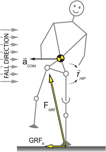
A prosthetic leg imposes limitations in the ability of users to actively control their mediolateral balance during standing and walking. The lack of muscle control, specifically around the amputated ankle, leaves prosthetic walkers unable to actively change the Centre of Pressure (CoP) under the foot during the stance phase on the prosthesis (ankle strategy) (Hof, van Bockel, Schoppen, & Postema, Citation2007). Prosthetic walkers compensate for this by changing certain walking parameters. For instance, they tend to stand longer on their sound leg and have a wider step on the prosthetic side (Hof et al., Citation2007; Jaegers, Arendzen, & de Jongh, Citation1995). Further, they bend their trunk towards the prosthetic side when walking (Jaegers et al., Citation1995). Mediolateral trunk motions may be a safety margin for the lack of CoP control. In this case, mediolateral trunk bending results from redirecting the horizontal component of the Ground Reaction Force (GRFh) for balancing purposes (Otten, Citation1999) by means of abduction and adduction hip moments of force. See Figure . This is essentially a hip strategy (Hof, Citation2007).
Figure 1. During single support, a residual velocity to the right will result in a fall if uncorrected for. An internal hip abduction moment (Thip) will accelerate the head, arms, trunk (HAT), and swing leg. The whole body consequentially accelerates in the opposite direction provided for by GRFh, given no slip occurs between the foot and the floor. If inertia is overcome these elements will rotate, thereby decreasing hip abduction angle. This is often inaccurately referred to as counter-rotation.
Altered walking parameters and residual mediolateral balance control mechanisms are still poorly understood. Walking parameters, such as step length, step width, and step frequency are mostly asymmetric, and asymmetry increases as stump length decreases. In turn, asymmetry decreases when walking speed is increased (Jaegers et al., Citation1995). Therefore, asymmetric walking parameters are likely a consequence of inaccuracy in foot placement, a lack of active ankle control, or both (Hof et al., Citation2007). This indicates a need for better mediolateral control on the prosthetic side during walking. Many studies have also reported asymmetrical lateral trunk bending towards the prosthetic side (Devan, Carman, Hendrick, Hale, & Ribeiro, Citation2015), mostly explained as resulting from hip abduction muscle weakness (Hendershot & Wolf, Citation2014). In one study, lateral trunk bending was found not to correlate with stump length (Jaegers et al., Citation1995), even though it may be expected that a shorter stump will result in decreased muscle function of the residual leg, and therefore less hip abduction strength. It seems hip abduction weakness can only partly explain observed prosthetic walking asymmetries, with lateral trunk bending being the most obvious consequence. It may very well be that it is not so much the hip abduction weakness itself, but rather the inability to effectively relay these moments to the prosthesis due to mechanical limitations. For instance, slip may occur between stump and socket due to a short lever arm. This would indicate the need for a more effective relay of hip abduction moments of force during prosthetic walking.
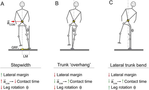
Another -complementary- possibility may be that mediolateral trunk bending acts as a stabilisation mechanism during prosthetic walking. Consider the three situations in Figure : A. To compensate for the lack of ankle in-/eversion, step width, and with it a safety margin (lateral margin, or LM) (Hak, van Dieën, et al., Citation2013; Hof et al., Citation2007), will be increased. Without lateral trunk bending, however, medial centre of mass (CoM) acceleration (acom) will increase, decreasing contact time unintentionally. Further, a stance leg rotation with respect to the vertical (Leg rotation angle ϴ) will lead to height loss and thus instability. B. If the whole body including the stance leg is rotated laterally as a whole, acom is decreased, solving the problem of a decreased contact time. LM however then gets unwantedly decreased or even inverted. Since a leg rotation angle ϴ is still present, stability remains decreased. C. Lateral trunk bending only will increase contact time without sacrificing LM, contact time, or stability ϴ; the stance leg remains upright.
Figure 2. Possible explanation for mediolateral trunk bending as a stabilisation mechanism during prosthetic walking. For simplicity, forces, margins, and accelerations are only drawn in A. (A) Step width is increased without bending the trunk. (B) A hypothetical situation in which the entire body is rotated. (C) Lateral trunk bending including a slightly wider step, and a vertical orientation of the prosthetic leg.
Mediolateral balancing may be improved by increasing the effectiveness of the hip strategy, thereby compensating for the lack of active ankle control. An increase in hip strategy effectiveness can be achieved through an increase in gain of the hip ab-/adduction moments of force (Mhip) with respect to the aforementioned GRFh; i.e. the GRFh-Mhip gain. To this purpose, a new, patented (WO2012091555, Citation2012) prosthetic prototype has been developed at the Center for Human Movement Sciences, University of Groningen, the Netherlands (Figures & ).
Figure 3. Frontal and sagittal view of the prototype.
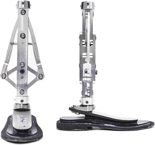
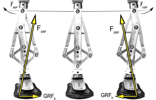
Figure 4. Mediolateral motion of the prototype. Assuming this is a right foot, a hip abduction (left image) or adduction (right image) moment will rotate and translate the femur with respect to the foot. A coupled but smaller counter-rotation (foot eversion, left image; foot inversion, right image) occurs, resulting in a combined functional change in both GRFh and CoP. Note that forces are not drawn to scale.
The prototype substitutes the tube between the prosthetic foot and socket or knee with a multi-bar mechanism, connected distally at the prosthetic foot and proximally at the socket or prosthetic knee. The prototype is a modified version of the Peaucellier mechanism (Ferguson, Citation1962), consisting of nine metal bars and six hinges, with one degree of freedom, which is mediolateral motion (Figure ).
It is presumed that the prototype allows for mediolateral CoP displacements during walking and mediolateral balancing, similar to an ankle strategy in unimpaired individuals. Further, the aforementioned GRFh-Mhip gain is expected to be larger than a fixed tube between foot and socket/knee. The mechanism retains or even slightly gains height when moving mediolaterally (Figure ) compensating for the height loss during normal mediolateral leg rotation. Height loss compensation is a prerequisite for mediolateral stability (see also Figure ). The main objective of this study is to validate whether using the prototype improves mediolateral balance control in prosthetic walking. Improvements are operationalised as changes in both CoP, and GRFh-Mhip gain. A secondary objective is to determine if prosthetic walkers are able to adapt their movement control in order to make use of the prototype. This should show as a reduction in lateral trunk bending during walking.
2. Methods
2.1. Subjects
Ten adult unilateral transfemoral amputee (TFA) subjects, and ten able-bodied subjects matched in age (± 10%), weight (± 10%) and sex will participate in this study. Due to the height of the prototype (23 cm) selection is limited to (unilateral) TFA subjects. Rehabilitation needs to be completed, and at least one year of daily prosthetic use is required for inclusion. Also, K-level mobility (Hafner & Smith, Citation2009) needs to be at least 3 as determined by a certified prosthetist/orthotist (CPO), indicating the ability to walk independently for an hour. Prosthetic walkers will be recruited via a database of the Orthopaedic Instrument Workshop (OIM, Haren, The Netherlands). Able-bodied subjects will be recruited through pamphlets and flyers distributed in various public places. Able-bodied subjects will predominantly be included to establish baseline values for comparisons. This study is approved by the local medical ethical committee (METc 2015/352), and registered in the Dutch Trial Register (NTR5360). Written informed consent will be obtained from all participants prior to measurements.
2.2. Apparatus
The intervention will be performed with the prosthetic prototype. See Figure in the background for details.
2.2.1. Full set-up
Prosthetic walkers will be fitted with an Otto Bock Axtion 1E56 prosthetic foot of 26 cm, the prototype, an Otto Bock single-axis knee 3R95, and their personal socket. The prosthetic foot will be used without a shoe or aesthetic cover, with a thin rubber strip customly attached to the sole by a CPO in order to increase friction and prevent wear of the carbon sole. A bear prosthetic foot is necessary since the prototype needs a stiff surface in order to function. Further, this prevents mediolateral slip between the core and aesthetic cover, and between the cover and the shoe, since slip will hinder functionality of the prototype. Although prosthetic foot length will deviate from the intact side, estimated maximum differences will be around 5 cm, which is expected not to influence walking pattern or measurement outcome. To accommodate for individual differences in leg length, the set-up will be lengthened by means of a tube of custom length, placed between the prototype and the prosthetic knee. The CPO will align the complete set-up beforehand.
2.2.2. Locking pin
The prototype contains a locking pin to physically lock the mechanism (Figure ).
Figure 5. Location of the locking pin on the prototype. Locked, it represents a classic set-up. Participants are less aware of the intervention in this manner.

2.3. Equipment
All measurements will take place in The Gait Real-time Analysis Interactive Lab (GRAIL, Motekforce Link, b.v., Amsterdam, The Netherlands) of the Center for Rehabilitation of the University Medical Center Groningen, Beatrixoord, Haren, the Netherlands. The GRAIL consists of an instrumented, dual-belt treadmill, containing two force plates measuring with a sample frequency of 1000 Hz, mounted on a 2-degree-of-freedom motion platform, combined with a 3 m diameter Virtual Reality (VR) environment projected on a 180 degree semi-cylindrical screen. Further, the GRAIL has an infrared motion-capture system consisting of 10 cameras (Vicon Bonita 10, Oxford, UK), with a sample frequency of 100 Hz. All subjects will be secured by a (non-weight bearing) safety harness attached to the laboratory ceiling. The GRAIL will be operated by a certified operator.
2.3.1. Angle excursion of prototype
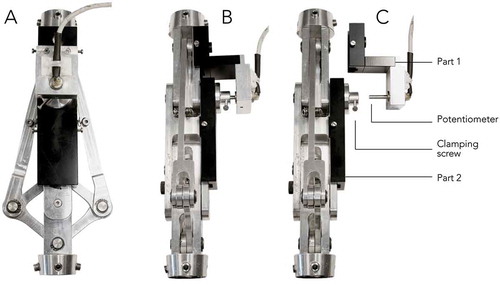
An analogue linear potentiometer (Rudiwo, 47 KΩ, 330° range) will measure angle excursions of the prototype (See Figure ) during walking Figure . A/D conversion takes place by an NI USB-6009 box at 14-bit analogue input resolution, set to a 0–5 V range, with an output frequency of 1000 Hz. The potentiometer was calibrated manually with an angular protractor, and estimated with a 5th-order polynomial with an average root mean square error of 0.8 degrees.
Figure 6. The set-up of the potentiometer mounted on the prototype. (A) Dorsal view of the prototype. (B) Sagittal view with the potentiometer attached to the prototype. (C) Sagittal view with the potentiometer unattached. Part 1 consists of a case for the potentiometer that can be bolted to the top bar of the prototype. Part 2 consists of a container that can be bolted to the middle bar of the prototype. The potentiometer gets inserted into the metal container of part 2. By means of a clamping screw the potentiometer can be attached frictionless. This way, the rotation angle between the top and middle bar of the prototype can be measured.
2.4. Experimental protocol
In a single experimental bout, subjects will be measured during three different walking tasks (see 2.4.2–2.4.4 below): (1) unperturbed walking, (2) walking with mediolateral balance perturbations, and (3) walking while stepping on light beams projected on the treadmill. The order of the walking tasks will be predetermined due to practical limitations. Measurements can be paused at any time when subjects indicate the need for a break. Breaks are allowed to prevent confounding results due to fatigue. The VR screen displays a simple virtual environment consisting of a walkway with a horizon and rudimental optical flow in order to enhance engagement. Able-bodied subjects will perform all walking tasks once. Subjects in the prosthetic walker group will perform all tasks twice; once with a “locked” and once with an “unlocked” prototype. These tasks will be cluster randomised, since locking and unlocking within a bout is not possible.
2.4.1. Familiarisation
Directly prior to measurements, prosthetic walkers will perform several walking bouts on the prototype at the OIM to adjust and familiarise themselves with the new prosthetic set-up. Both prosthetic walkers and reference subjects will briefly walk on the treadmill in order to get acquainted with treadmill walking. This will take around two minutes, and can be extended for another bout if the need is indicated by subjects. Subjects will be excluded for measurement if they are unable to walk independently (i.e. without help or external support) on the GRAIL treadmill.
2.4.2. Comfortable walking velocity
Before recording, subjects will walk on the treadmill for a full minute with the treadmill in self-paced mode (Sloot, van der Krogt, & Harlaar, Citation2014). Subjects will be instructed to walk “at a velocity that they are comfortable with; as if walking outdoors for a leisurely stroll”. Average walking velocity will be calculated by taking the average walking velocity in the last 20 s of that minute. This will be the comfortable (100%) walking velocity, and will be used as the fixed walking velocity in all measurements, unless stated differently.
2.4.3. Unperturbed walking
After determination of the comfortable walking velocity, measurements start immediately. Three bouts will follow in a random order in which subjects will walk for one minute on their comfortable velocity (100%), a slow (80%) and a fast velocity (120%). The end of every minute will be indicated by three short sound beeps, played 5 s before every minute ends.
2.4.4. Mediolateral balance perturbations
For the perturbation task, subjects will be mediolaterally perturbed while walking at their comfortable walking velocity. Perturbations consist of medial or lateral pulls; a horizontal translation of the treadmill perpendicular to the walking direction (See Figure ).
Figure 7. At terminal swing of the intended leg (here: right leg) the treadmill platform will start moving 0.05 in 750 ms. The acceleration phase lasts for 360 ms with a maximum acceleration of 0.7 m/s2, followed by a deceleration phase for 390 ms, at a maximum deceleration of 0.72 m/s2. Platform movements will be randomly to either the medial, or the lateral side.

Perturbations will be applied to the prosthetic or self-declared dominant side (able-bodied), and will be offered randomly between 8 and 12 steps. Due to the low maximum acceleration of the platform, perturbations will start at terminal swing of the intended leg. This elicits an initial balance response during stance on the intended leg and prevents a primary long-latency response contralaterally (Hof & Duysens, Citation2013). After a perturbation, the platform remains in position for five seconds, after which the platform moves back slowly to its initial position. The process then repeats. A total of 8 lateral and 8 medial perturbations will be applied, randomly to each direction.
2.4.5. Self-initiated foot placement
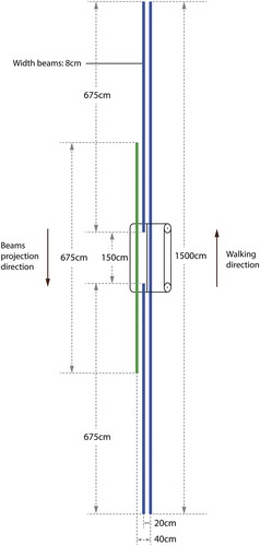
In this task, subjects will walk while stepping on two blue light beams projected on the belt of the treadmill, one for each foot, projected 20 cm apart from one another. This imposed normal width walking is comparable to an average of 23 cm step width found in a study on unimposed step widths of able-bodied subjects during unperturbed treadmill walking (Hak, Houdijk, et al., Citation2013). After some time a third, green beam will be projected onto the belt 20 cm lateral to one of either blue beams. All beams come into view on the screen and at the anterior side of the belt, “move along” at the same velocity as the belt, and disappear at the posterior side of the belt (Figure ). Subjects will be instructed to step on the blue (solid blue in Figure ) beams when projections have arrived below them. As soon as the green beam (striped green in Figure ) is within stepping range, subjects may step outward from the blue to the green beam with the leg corresponding to the projection side of the beam. Projection of the blue beam medial to the green one is then interrupted for 1.5 m. As soon as the blue beam reappears, subjects may step back inward from the green to the blue beam. An overlapping period is present in which both beams are visible (Figure ). Subjects will be instructed to step outward or back inward only once from either beams whenever they feel comfortable. The overlap prevents “spotting”, i.e. subjects altering their step length or contact times in order to “hit” the beams. A total of 5 beams on the left and 5 on the right will be projected, randomly to either side, providing us with (1) imposed normal width walking, (2) imposed wide stride walking, (3) stepping outward (for each leg), and (4) stepping inward (for each leg).
Figure 8. Top view of the beam projection layout, drawn to scale. Lengths and relative positions for the various beams are shown. Beams first appear on the VR-screen and move towards and onto the treadmill surface taking into account optical flow. Beam progression velocity is synchronised with treadmill velocity. Note the overlap (262.5 cm) between the green/striped and blue/solid beams.
2.5. Data collection
All data will be collected with D-Flow (version 3.28). Kinetic data (Forces, moments, and CoP) from the two separate force plates corresponding with each foot will be collected. The Motek full body Human Body Model version 2 (HBM2), consisting of 47 markers will be used to collect labelled kinematic data from reflective markers (van den Bogert, Geijtenbeek, Even-Zohar, Steenbrink, & Hardin, Citation2013). During data collection, force plate data will be down sampled to 100 Hz and filtered in real-time with a 2nd-order low-pass Butterworth filter with a cut-off frequency of 10 Hz. All kinematic data will be low-pass filtered in real-time with a 2nd-order low-pass Butterworth filter with a cut-off frequency of 4 Hz. Both filters are not bi-directional. Potentiometer angles will be collected continuously and unfiltered throughout measurements.
2.6. Data analysis
All data will be analysed using custom written software in MATLAB (version 9.3). All outcome measures will be cut to and normalised over the duration of one gait cycle. For the unperturbed walking task, all outcome measures will be averaged across the total number of strides in the cycle per trial. For the perturbation task, all outcome measures will be averaged over the in total 10 perturbations per side. For the self-initiated foot placement task, all outcome measures will be averaged over the 5 trials per stepping condition.
2.6.1. Mediolateral balance control measures
The following balance parameters will be analysed: GRFh, CoP, CoM, potentiometer angle, hip ab-/adduction moment, and (upper) trunk angle. Additional measures will be foot progression angle (as possible confounder), sagittal axis ankle and hip joint angles, as well as their first- and second-order derivatives. Step length, step width, and step frequency will be calculated as well.
2.7. Statistical analysis
To determine the effect of the prototype in all walking tasks on balance specific parameters, i.e. GRFh, CoP, Mhip, and mediolateral trunk angle, several statistical analyses will be performed. Pattern identification methods, e.g. Bootstrapping (Duhamel et al., Citation2004; Lenhoff et al., Citation1999) or Statistical Parametric Mapping (SPM), will be performed to analyse continuous time series data. These methods allow for significance testing over the entire gait cycle as a continuous curve. Variance analysis methods will be used for discrete variables, e.g. foot progression angle, and step parameters. Differences between prosthetic walking with and without a functioning prototype will be established, as well as differences between prosthetic walkers (in both conditions) and able-bodied subjects. Significance testing will be performed beforehand to exclude potentiometer angle (prosthetic groups only), and step width (all groups) as possible covariates. P-values below 0.05 will be considered significant. Bonferroni correction(s) (p < 0.025) will be applied for planned post hoc analysis. For unplanned further comparisons, Tukey’s HSD will be used. Subjects terminating prematurely will be replaced.
3. Discussion
While many studies focus on sagittal plane improvements during locomotion, often by means of microprocessor controlled devices, the current study focuses on frontal plane additions. Moreover, the design takes active balance control into consideration. Prosthetic walkers experience difficulties in active (mediolateral) balance control. This study aims to validate a new prototype on mediolateral balance control, quantified by variations in GRFh and active CoP displacements under the prosthetic foot during walking. By using the muscles around the hip joint in a more effective manner than with classic prosthetic designs, it is expected that the prototype will be able to improve mediolateral balance control in prosthetic walking. It is currently unknown if prosthetic walkers are able to adapt to the prototype, and able to use a more effective hip strategy as a mediolateral balance control strategy. If so, it is expected that lateral trunk bending will be reduced during walking. It is further expected that this study will provide us with new insights on asymmetric lateral trunk bending, as well as more general insights into prosthetic walking. Since this is a laboratory study, only efficacy of the prototype can be established. The effect of wearing the prototype on a daily basis by a large group of prosthetic walkers remains to be studied. Future efforts are needed to develop the prototype into a readily available prosthesis. This entails, but is not limited to, robustness against wear and tear, aesthetic improvements, and design optimisations to make the device suited for walking outdoor. Outdoor we are faced with various surfaces, all with different stiffness and damping properties. On a compliant surface however, the foot will “sink”, i.e. invert or evert without finding support. This will hinder the relay of the hip ab-/adduction moments. A sinking foot will also result in height loss. Surface compliance has implications for the choice of aesthetic covers and shoe soles. A slip free connection between foot and shoe needs to be developed. Vice versa, the choice for covers and shoes has implications for the design of the device. There will be a future need to optimise the mechanism for more compliant surfaces. Finally, the prototype should be able to function and even aid in mediolaterally tilted surfaces. Since mechanism rotation is limited, the amount of surface tilt that can be accommodated for is as well. Designing prosthetic devices that afford control through “natural” interactions with the prosthetic wearer is in our opinion a critical element in the design of prosthetic devices.
Disclosure Statement
The authors report no conflicts of interest.
Additional information
Funding
Notes on contributors
Evert S. van Hal
Our research group consists of a collaboration between the Center for Human Movement Sciences and the Center for Rehabilitation, both part of the University of Groningen, University Medical Center Groningen, Groningen, the Netherlands. Our research interests include motor learning, biomechanics, rehabilitation, prosthetics, assistive technology, and (clinical) gait analysis.
Juha M. Hijmans
Our research group consists of a collaboration between the Center for Human Movement Sciences and the Center for Rehabilitation, both part of the University of Groningen, University Medical Center Groningen, Groningen, the Netherlands. Our research interests include motor learning, biomechanics, rehabilitation, prosthetics, assistive technology, and (clinical) gait analysis.
Klaas Postema
Our research group consists of a collaboration between the Center for Human Movement Sciences and the Center for Rehabilitation, both part of the University of Groningen, University Medical Center Groningen, Groningen, the Netherlands. Our research interests include motor learning, biomechanics, rehabilitation, prosthetics, assistive technology, and (clinical) gait analysis.
Egbert Otten
Our research group consists of a collaboration between the Center for Human Movement Sciences and the Center for Rehabilitation, both part of the University of Groningen, University Medical Center Groningen, Groningen, the Netherlands. Our research interests include motor learning, biomechanics, rehabilitation, prosthetics, assistive technology, and (clinical) gait analysis.
Related Research Data
References
- Devan, H. , Carman, A. , Hendrick, P. , Hale, L. , & Ribeiro, D. C. (2015). Spinal, pelvic, and hip movement asymmetries in people with lower-limb amputation: Systematic review. Journal of Rehabilitation Research and Development , 52, 1–20. doi:10.1682/JRRD.2014.05.0135
- Duhamel, A. , Bourriez, J. L. , Devos, P. , Krystkowiak, P. , Destée, A. , Derambure, P. , & Defebvre, L. (2004). Statistical tools for clinical gait analysis. Gait Posture , 20, 204–212. doi:10.1016/j.gaitpost.2003.09.010
- Ferguson, E. S. (1962). Kinematics of mechanisms from the time of watt [Internet]. Smithsonian Institution Retreived Dec 19, 2016 from: http://ebooks.library.cornell.edu/k/kmoddl/pdf/009_001.pdf.
- Hafner, B. J. , & Smith, D. G. (2009). Differences in function and safety between medicare functional classification level-2 and −3 transfemoral amputees and influence of prosthetic knee joint control. Journal Rehabilitation Researcher Developments , 46, 417–433. doi:10.1682/JRRD.2008.01.0007
- Hak, L. , Houdijk, H. , van der Wurff, P. , Prins, M. R. , Mert, A. , Beek, P. J. , & van Dieën, J. H. (2013). Stepping strategies used by post-stroke individuals to maintain margins of stability during walking. Clinical Biomechanics , 28, 1041–1048. doi:10.1016/j.clinbiomech.2013.10.010
- Hak, L. , van Dieën, J. H. , van der Wurff, P. , Prins, M. R. , Mert, A. , Beek, P. J. , & Houdijk, H. (2013). Walking in an unstable environment: Strategies used by transtibial amputees to prevent falling during gait. Archives Physical Medica Rehabilitation , 94, 2186–2193. doi:10.1016/j.apmr.2013.07.020
- Hendershot, B. D. , & Wolf, E. J. (2014). Three-dimensional joint reaction forces and moments at the low back during over-ground walking in persons with unilateral lower-extremity amputation. Clinical Biomechanics , 29, 235–242. doi:10.1016/j.clinbiomech.2013.12.005
- Hof, A. L. (2007). The equations of motion for a standing human reveal three mechanisms for balance. Journal Biomechanics , 40, 451–457. doi:10.1016/j.jbiomech.2005.12.016
- Hof, A. L. , & Duysens, J. (2013). Responses of human hip abductor muscles to lateral balance perturbations during walking. Experiments Brain Researcher , 230, 301–310. doi:10.1007/s00221-013-3655-5
- Hof, A. L. , van Bockel, R. M. , Schoppen, T. , & Postema, K. (2007). Control of lateral balance in walking. Experimental findings in normal subjects and above-knee amputees. Gait Posture. , 25, 250–258. doi:10.1016/j.gaitpost.2006.04.013
- Jaegers, S. M. , Arendzen, J. H. , & de Jongh, H. J. (1995). Prosthetic gait of unilateral transfemoral amputees: A kinematic study. Archives Physical Medica Rehabilitation , 76, 736–743. doi:10.1016/S0003-9993(95)80528-1
- Lenhoff, M. W. , Santner, T. J. , Otis, J. C. , Peterson, M. G. E. , Williams, B. J. , & Backus, S. I. (1999). Bootstrap prediction and confidence bands: A superior statistical method for analysis of gait data. Gait Posture , 9, 10–17. doi:10.1016/S0966-6362(98)00043-5
- Otten, E. (1999). Balancing on a narrow ridge: Biomechanics and control. Philosophy Transactions R Social Lond B Biologic Sciences , 354, 869–875. doi:10.1098/rstb.1999.0439
- Otten, E. (2012). WO2012091555 . World Intellectual Property Organization. Retrieved from https://patentscope.wipo.int/search/en/detail.jsf?docId=WO2012091555
- Sloot, L. H. , van der Krogt, M. M. , & Harlaar, J. (2014). Self-paced versus fixed speed treadmill walking. Gait Posture , 39, 478–484. doi:10.1016/j.gaitpost.2013.08.022
- van den Bogert, A. J. , Geijtenbeek, T. , Even-Zohar, O. , Steenbrink, F. , & Hardin, E. C. (2013). A real-time system for biomechanical analysis of human movement and muscle function. Medica Biologic Engineering Computation , 51, 1069–1077. doi:10.1007/s11517-013-1076-z