
 ?Mathematical formulae have been encoded as MathML and are displayed in this HTML version using MathJax in order to improve their display. Uncheck the box to turn MathJax off. This feature requires Javascript. Click on a formula to zoom.
Abstract
Today, the turbomachinery engineering plays a vital role in the field of air breathing propulsion, most importantly the components like compressor, turbine and its possible numerical strategies to improve the overall efficiency especially in the transonic flow conditions. The main objective of this paper is to address the numerical solution for most uncertain problem like unsteady and non-uniform flow across the axial-flow compressor. The axial-flow compressor distorted flow problem is modeled and analyzed by means of a systematic three-dimensional numerical approach. Particularly, the rotor inflow instability implications of an axial compressor stage are carried out. Geometry is created using ROTOR-37 coordinates for numerical analysis and the results are validated in contradiction of experimental data available from literature, by imposing various combinations of Mach numbers from 0.8 to 1.2 and the engine mass flow rate of incoming air. The results highlighted that the rotor blade main distortion effect was noticed at near the tip region and as well as the hub corners of the blade. Numerical simulations also revealed that due to the distortion influence, the stream flow separation on pressure side of the blade is more. Moreover, these calculated figures have more significance for better aero-mechanical features of axial-flow compressor.
Keywords:
PUBLIC INTEREST STATEMENT
An axial compressor is a compressor that can continuously pressurize gases. Transonic axial-flow compressors are extensively used in aircraft engines to produce maximum pressure ratios per stage. An airplane flying at speed of sound creates a disturbance in the air and sends out pressure pulses in all directions and is termed as transonic. High stage pressure ratios are important because they make it possible to reduce the engine weight and size and, hence the investment and operational costs. Performance of transonic compressors has today reached a high level. A small increment in efficiency, for instance, can result in huge savings in fuel costs and determine a key factor for product success. Another important target is the improvement of rotor stability, resulting in a wider working range. The flow field that develops inside a transonic compressor rotor is extremely complex and presents many challenges to compressor designers.
1. Introduction
Today, the aircraft industry is looking for faster and safe operating engines. Aircraft engines operate on Brayton cycle, its efficiency mainly depends on the compressor and turbine components performance. This paper is completely focused on axial-flow compressor performance under distorted conditions. Till the subsonic speed engine flow stream is almost smooth, there is no much turbulence occurring in the rotor blades. But when the engine operates at higher Mach number especially transonic speed (0.8–1.2), the turbulence drastically increases. Therefore, this research article gives more emphasis on the Mach number study under transonic flow conditions. Distortion is the condition where the huge turbulence formation takes place inside the flow field of compressor blades due to non- design environment (Jian & Hu, Citation2008). When the aircraft operates more than subsonic speed, compressor undergoes non-design environment conditions.
Non-design environment circumstances arise because of situations like engine inlet configurations, extreme aircraft maneuvers, engine inlet flow boundary interactions, sometimes shock waves from nearby other aircrafts, atmospheric air turbulence, etc. Under these non-design environmental conditions, the performance stall in the compressor may fluctuate and form pressure disturbances which will eventually reduce the performance of the compressor.
In general, any aircraft jet engine consists of components like compressor, combustion chamber, turbine and nozzle. There are two types of compressors used in the aircraft engines, one is centrifugal (sometimes also referred as radial compressor) type and other one is axial-flow-type compressor. Centrifugal-type compressors are used for low-pressure small turbojet engines applications, whereas axial-flow compressors are used in large modern turbofan engines. Axial-flow compressor has a series of stages. Each stage has one rotor blade and one stator blade. The rotor blade plays a vital role in the compressor stage which increases the kinetic energy whereas the stator blade increases the static pressure of the fluid.
When pilot maneuvers the aircraft, during the situations like sudden pitch up, pitch down, sudden rolling, sudden yawing moments etc., the rotor blades undergo huge air turbulence due to distortion effect. The formation of huge air turbulence in the compressor stages leads to decrease the stall performance in the entire compressor. Avoiding complete distortion effect in the rotating components is practically not possible by any of the modern available techniques (Jian & Hu, Citation2008). But it is possible to minimize the distortion effect by incorporating suitable operating conditions using modern computational fluid dynamics (CFD) techniques. To know the axial-flow compressor distortion effect, this paper makes an effort to identify the possible effects of distortion under transonic flow conditions. Distortion effect is categorized by two subsections. The first subsection of distortion effect is finding the blockage between rotors to stator blade. Second subsection is measuring the distortion effect across the rotor blade in terms of pressure, velocity and Mach number parameters.
2. Literature review
Jian and Hu (Citation2008) aim at finding the performance of axial-flow compressor rotor by simultaneously comparing the results of casing treated and untreated rotors, with and without inlet pressure distortion. This numerical investigation was accomplished using unsteady 3D Navier–Stokes equations. The tool used for conducting the flow simulation was NUMECA FINE. First, the symmetry of the circumferential grooves is exploited to conduct steady-state simulations of a single blade passage. An additional 3D time accurate analysis is performed by taking one-tenth of compressor stage rotor blade passages. From this research, it is clear that groove casing treatment improves the compressor stage efficiency. The flow conditions in this research article were only limited to low-speed Mach number and therefore the tip leakage was also restricted to minimum losses.
Min, Duffy, Choi, Provenza, and Kray (Citation2013) studied the performance of axial-flow compressor for different pressure load conditions when the rotor blade undergoes vibration phenomena. This research paper focuses more into reducing this effect by studying the piezoelectric vibration control. This will help in designing thinner blade models with higher performance capabilities with reduced damage due to vibrations. The purpose of the paper is to first analyze a finite element composite model coupled with a resistor (R), an inductor (L) and a capacitor (C) (RLC) circuit to simulate rotating blade conditions and compare numerical and experimental results. The results show that the damping of piezoelectric vibrations of the blades has significant benefits. But it needs further study to apply it in commercial aircraft engine blade system.
The objective of Suder et.al (Citation2001) was to study steady tip injection on a single rotor stage and figure out its effect on the stability of compressors. Their work was further aimed at figuring out how to maximize the compressor stability for a given level of injected flow. Methodology of the work included employing CFD simulations using a mass-injection model to study the fluid mechanics process by which tip injection increases compressor stability and then further experimental study on the arrangement of injectors and its parameters. The injection parameters like flow momentum, velocity and distribution of the injectors were varied to study maximum stabilization criteria. From the CFD analysis, it was concluded that the injectors increased stability by reducing blade loading and incidence at the tip as well as that injector effectiveness depends on the injector exit axial velocity and momentum. The experimental results implied that the parameter that is directly related to range extension is the mass averaged axial velocity at the blade tip and that it is independent of the arrangement of the injectors. The work however only focused study on a single rotor stage but the authors believe that the implementation of injectors at inlet and mid stages would increase the stability of multistage compressor.
Cong-Truong Dinh, Heo, and Kim (Citation2015) tested blade tip injection with National Aeronautics and Space Administration (NASA) rotor 37 in an axial compressor at transonic conditions. This was combined with an introduction to casing groove. The performance study was based on 3D Navier–Stokes equations. Effects of operational and dimensional parameters on performance factors such as the stall margin, total pressure ratio and adiabatic efficiency are investigated in the study. It was concluded that a combination of tip ejection and injection in a casing groove is more effective than in the case where only injection is used. Additional optimization of geometry in the combination of ejection and injection can be performed to enhance the performance of the compressor.
SUN Xiaofeng, Dakun, and Weiwei (Citation2011) set a stall inception model for compressor blades in transonic flow. The stability and shock wave effects are considered in this model. Mode-matching technique is used to derive a set of homogenous equations to obtain steady equations for the solution of an unsteady flow field. The research is conducted by way of numerical analysis and experimental data. This model has not considered the effect of centrifugal force due to the radial velocity which possibly will give more accurate results.
Ren and Chunwei (Citation2016) conducted a numerical study on the rotor’s tip clearance flow when the compressor is subjected to transonic conditions. Using a discontinuous Galerkin method, Spalart–Almaras turbulence model is discretized in physical space with 3D Navier–Stokes equations. To estimate the blockage in the transonic flow, a blockage indicator has been introduced to the rotor. The tip clearance flow is subjected to the blockage which initially increases and then as the cross-section moves downstream, it decreases. The flow is found to be well organized when the blade clearance is inducted in a mass flow rate condition which is 98% choked.
Zhihui and Liu (Citation2017) optimized the application of blade-end treatment to axial-flow compressors. The blade-end treatment changes the blading loading distributions in the spanwise directions. By optimizing the blade-end treatment, the shroud region incurred a reduction in loss. Numerical and experimental results show that the application of the end bend is not effective to tip leakage losses. NASA rotor 35 was considered in the compressor. It was optimized by utilizing Artificial Neural Network model combined with genetic algorithms to corroborate the flow mechanisms. Owing to the restraint of computation capability, a better method to consider is to combine the optimization algorithms and the summarized flow control mechanisms to reduce computational costs.
Xuemin, Zhang, and Chunxi (Citation2017) numerically investigated the acoustics in a two-stage axial compressor with a variable pitch and the effect on performance when five different blade tip patterns are used. The computational methodology includes numerically simulating a fan model by applying CFD with different blade patterns. The study concluded that the direct groove tip performs the best as compared to forward and backward step groove tips and a double groove tip. In the case of a reverse groove tip, its efficiency is limited to low mass flow rates.
Shaobing and Jingjun (Citation2016) conducted a numerical study for a highly loaded rotor of a compressor subjected to transonic regime to determine the variation of performance at different positions of a blade tip winglet. The numerical model of NASA rotor 37 was simulated in NUMECA. Among the configurations drawn for analysis, pressure side winglet is found to be more effective than suction side winglet. This is due to the tip blockage caused by shock–vortex interaction. The effective pressure side winglet has already been manufactured and is yet to undergo tests.
Poursaeidi, Tafrishi, and Amani (Citation2017) investigated the impacts of solid particles that cause erosion of the blades in the entry stage of the compressor. The study was conducted both in experimental and computational analysis. The setup included AISI Custom 450 stainless steel for the rotor blades. Depending upon the trajectories of sand and quartz, the erosion was most effective at the leading edge around the shroud casing, which is the rotor blade tips and stator blade hub. It is hence proven that erosion rate depends on the erosion angle which is maximum at 20° and negligible at 90°. However, it was discovered that the solid particles do not impact the suction surface and hence the inlet guide vanes experience lowest rate of erosion.
Zhou, Zhao, Cui, and Jianzhong (Citation2017) investigated the axial effect of the recirculation in the slots and flow at the blade tip is studied to determine the flow properties at four different positions. The numerical model of NASA rotor 67 was simulated in EURANUS and obtained by running through unsteady numerical simulations. The results show that a reduction in improvement is obtained with the shifting of slots upstream or downstream. It is concluded that the intensity of recirculation in the slots has greater importance on the stall margin improvement. Daabo, Saad Mahmoud, Al-Dadah, and Al Jubori (Citation2017) conducted numerical analysis on varying stage axial and radial turbines for the application of Brayton cycle running on solar power. CFD is used to draw visualizations of the flow properties inside the turbine as well as to obtain the efficiency and power output at various boundary conditions. The results concluded that the single-stage turbine delivered greater power, while the dual-stage outnumbers at off-design conditions. Further analysis could have determined the preferred configuration between the dual-stage axial turbine and the single-stage radial turbine.
Mao, Liu, and Zhao (Citation2018) conducted a study on the impact of circumferential grooves casing treatment in an axial-flow compressor. The effects are studied on counter-rotating compressor stages to determine unsteady flow behavior and its mechanisms leading to enhancement of stability. The simulations were performed using a CFD solver of EURANUS international. Due to constraints in computational costs, only two rotors were used. The results show the groove casing treatment has negligible effect at the peak efficiency point, while there is a substantial increase in performance near the stall region. The actual performance figures are lower than that obtained due to the presence of multiple blades. Reid and Moore (Citation1978) studied High-loaded and high-speed axial-flow compressor both theoretically and experimentally and well calculated.
Wang, Lu, Liu, and Hu (Citation2018) performed an unsteady numerical study on a compressor under transonic conditions for tip clearance flow. The rotor of the first stage in a compressor was inducted by a CFD solver, and steady and unsteady computations were performed. The results showed that the rotating instability phenomenon occurs along the circumferential direction on a multi-passage structure. Due to the weak interaction between the tip leakage vortex and the shock near the stall region, each blade shows synchronous oscillations in the co-swirl inlet conditions.
Hossein (Citation2017) reported a parametric study on the stalling characteristics of an axial-flow compressor flowing at transonic velocities. The test was conducted on a NASA rotor 67 and numerically solved using CFX solver and CFD code. The numerical analysis shows the injectors penetrated radially in a fan reveal a stall condition that is originated at the tip called wall stall. When the injector height is doubled to the tip clearance, the wall stall condition changes to blade stall condition. The study on the injectors could have been protracted to discrete injector instead of limiting to annular injectors.
Biollo and Benini (Citation2013) studied the aerodynamics of transonic compressors and their recent advancements to increase stagewise pressure ratios. Formation of shockwave and tangential deflections of the flow play a crucial role to achieve higher pressure ratios. Casing treatments have been applied to improve the overall efficiency and working range of the compressor. The study concluded that pressure ratios are vital for the exact use of the compressor that is low-pressure ratios and high efficiency in subsonic compressors, while lower efficiency and higher pressure ratios are used in supersonic compressors. A study on counter-rotating rotors could have been included since they provide for the highest pressure ratio.
Alone et al. (Citation2016) conducted an experiment on a single-stage high-speed transonic compressor. The compressor was coupled to axial extensions ranging from 20% to 100% of bend skewed casing treatments. The stage efficiency is at its highest and stall margin is at its lowest at the ideal extension of the skewed casing treatment. The results showed that though axial extensions provide 5% penalty in stage efficiency, peak efficiency is obtained at 40% axial extension. A CFD analysis on the unsteady flow physics for the compressor subjected to axial extensions of bend skewed treatments would have provided a better understanding on the experiment.
Mohsen, Owis, and Hashim (Citation2017) undertook a parametric numerical study on the performance of transonic compressor blades having tandem rotors. The rotor proposed for the investigation was NASA rotor 37 at mid span section numerically tested using CFD codes. The aft profile is modified to simulate performance of tandem rotor. Initially, the design flow rate is conducted in two-dimensional analysis which is then converted to a three-dimensional analysis. The results concluded that due to negative incidence angle of the aft rotors, the tangential overlap ratio needs to be reduced to avoid tip stall. The results could vary depending on the design of the rotor since only one design is considered in this investigative study.
From the presented systematic review, it is clear that performance of the compressor is unstable during non-design environment conditions. Also, noted that due to the unsteady aircraft conditions, the compressor stall performance merely falls down. Clear understanding of the compressor rotor-stator flow is very much essential especially for aircraft higher speed operating conditions. The present research work attempts a clear flow simulation analysis under distorted conditions at transonic speed Mach numbers, so that one can understand the full stall behavior effectively.
3. Methodology with boundary conditions
In order to investigate the flow behavior of axial-flow compressor under distorted conditions, NASA Rotor 37 blade reference data were used (Reid & Moore, Citation1978). To know the flow deflections and flow separations, more focus is given to only rotor blade because the rotor contributes more energy to increase the kinetic energy of the fluid. In this paper, the work showed is only on single-stage axial-flow compressor which includes one rotor and stator blade. The complete axial-flow compressor rotor design data are shown in Table .
Table 1. Compressor rotor blade design Data (Reid & Moore, Citation1978 )
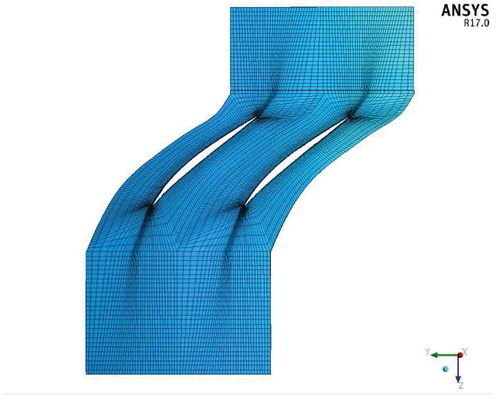
In this paper, axial-flow compressor single-stage (rotor and stator) blades are considered. According to the standard reference for generating the model, the compressor rotor and stator blades are considered as 36 and 37, respectively. But, to reduce the computational time effort, the work done is only on one single stage. For the modelling of the complete single-stage compressor, blade pitch ratio is considered as 1.2 instead of 1.278 of the original geometry. Also, the rotor blade twist angle taken as 40° and stator blade twist angle is taken as 30°. Using ANSYS® tool, computational rotor and stator mesh grid were generated. Numerical grid techniques play a vital role in solving the turbomachinery components problem. Algebraic multigrid method was chosen to solve the distorted effects on the axial-flow compressor rotor blade. At the rotor blade interface, a mixing plane approach was incorporated to see the fluid structure interaction losses around the blade geometry. Throughout the computational domain, good quality prism-type mesh elements were maintained with 12–15 layers with the grid accuracy size of 25–28 micrometers. From the hub to tip, the mesh growth rate was uniformly maintained with same number of layers to predict the exact vortex formation. Surface of the rotor blade was meshed with tetrahedral mesh elements. The computational rotor blades model and mesh grid diagrams are as shown in the Figures –.
Figure 1. Blade basic coordinates representation Hossein (Citation2017).
Figure 2. ANYS geometrical model of rotor 36 blades.
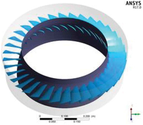
Figure 3. Geometrical details of rotor blade in ANSYS®.
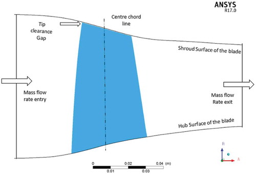
Figure 4. Representation of mesh elements on compressor stages.
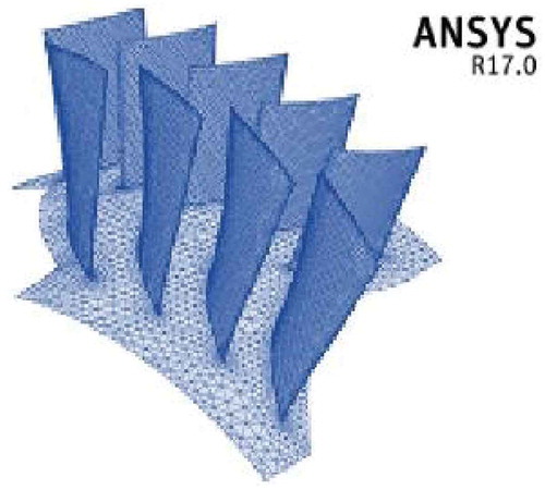
Figure 5. Representation of mesh elements near the leading edge and trailing edge in ANSYS®.
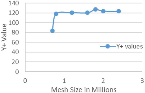
To get good simulation results between the rotor and stator flow passage, the boundary values on the computational grid Y+ axis should be a positive high value. To maintain the Y+ higher values around the rotor blade, prism layers were selected using tetrahedral grid elements. The grid point accuracy was maintained as 25 µm for better resolution of the rotor to stator flow simulation results. For better consistency of the simulation results, grid independence check was also performed and is shown in Figure . Better results are achieved at 2.4 million mesh size and in all cases, the solutions also converged too.
Figure 6. 100% design speed, mesh independence check of rotor 37.
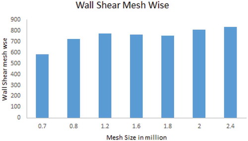
The grid independence study reveals that flow simulation results are matching well with the experimental data at 2.05 × 10⁵ mesh elements and it was well suitable for the Mach numbers 0.8–1.2 speeds. Y+ scalable wall function values are also well matched with corresponding grid independence check values and are shown in the Figure . This figure represents for the complete flow domain on the rotor and stator stage Y+ value. The selection of aircraft axial-flow compressor stage speed (Reid & Moore, Citation1978) under unsteady conditions and the mere deflected performance calculations were well reported by Reid et al.
Figure 7. 100% design speed for the complete flow domain with stage model Y+ values along with the mesh size.
To get the complete flow simulation results between the rotor and stator, the grid over the blades should be error-free and it was well maintained in this work. Also, the flow domain was defined with inlet and outlet boundary conditions. Using the ANSYS® CFD tool, flow simulations were successfully completed under transonic conditions. To know the distorted phenomena, the flow simulations were set with the algebraic multigrid method. It is also noticeable that in the finite discrete method, third-order high-resolution scheme was maintained throughout the simulations. So that, the flow interaction between the rotor and stator flow was well captured and also helps to see clear flow passages from hub to tip of the blade. Simulations performed is based on the clean off-design conditions with steady multiple frame of reference in order to capture the flow shock interactions and flow shock separations on the rotor blade. To see the distortion effects between the rotor and stator blades, a mixing plane approach was selected during the simulation. ANSYS® 17.0 version Fluent® software was used to solve the Pressure base-coupled Navier–Stokes solver. For solving the solver, the least squares cell-based discretization option is selected in solution methods.
In this research work for the compressor stage simulations, ANSYS® 17.0 CFD turbulence model was used to solve the flow domain boundary conditions. To find out distortion effect under the transonic flow condition on the compressor stage, the eddy-viscosity Reynolds-Averaged Navier–Stokes (RANS) equation along with the k−ε turbulence model is used. The most common k−ε turbulence model was used in this simulation, to compute the high complexity turbulent flow at transonic conditions in the compressor rotor. The theory of scalable wall function methodology (Zhou et al., Citation2017) was considered in the analysis. According to the analytical scalable wall function approach, an improved turbulent velocity scale is used. This value is generally dependable on the turbulent model kinetic energy at blade suction side or pressure side wall node kp
.
As a result, an altered Y+ based on can be evaluated using:
The logic behind implementing the scalable wall function method is to minimize the numerical y+ number utilized in logarithmic formulation. For the unsteady and non-uniform flow, generally the scalable wall function Y+ value should not be more than 15 (Reid & Moore, Citation1978). Therefore in this simulation work, the value of Y+ scalable wall function is maintained as 10.06 which is reasonable for all real flow boundary conditions. To calculate the flow near wall distortion effect in the compressor stage, the k− ε model needs to be changed. The wall functions for transonic flow are defined in the above two Equations (1–2). By incorporating the above said Y+ scalable wall function, the logarithmic wall profile will exist throughout the stage flow domain, and also flow turbulence effect can simulate effectively under the given set of boundary conditions.
To analyze the flow distortion numerical simulation on axial-flow compressor at the inlet condition, it is required to impose the appropriate flow angle, total pressure and total temperature. Axial-flow compressor stage inlet conditions are fixed at Inlet total temperature (T01) = 288.15 K, Inlet total pressure (P01) = 101,325 Pa, respectively. In this work, the convergence criteria considered for the complete stage is 10−06 (i.e. 0.000001). Time step determines the adequacy of transient process in compressor stage numerical modelling and hence the average flow field is shown throughout the analysis.
When it comes to axial-flow compressor stage outlet flow conditions especially 100% speed designed line, that too near-choked flow region relative static pressure (Prel.static) must set from zero Pascals. This value is maintained until it reaches near-stall conditions. Because at near-stall region, only the value of mass flow rate is imposed at the stage exit condition. To have the different simulation working points, the mass flow rate is progressively reduced. Finally, since the flow behavior is restricted to one single stage, part of the compressor geometry has been modeled, in the lateral surface of the flow field and the rotational periodic margin conditions were given. The angular velocity value is also incorporated in the stage as mentioned in the 100% design speed line of reference (Reid & Moore, Citation1978). Consequently, in the computational model, the rotation is imposed to the rotor blade as shown in Table by giving a rotational speed of 17,188.7 rpm as the boundary conditions in ANSYS® Fluent® tool.
Table 2. Boundary Conditions
4. Results and discussions
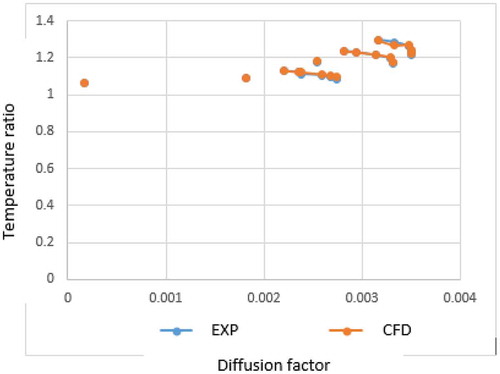
With the numerically analyzed results and experimental data, the calculated efficiency graphs are shown effectively. It is observed that the error between the numerical distorted results and experimental data is percentage of the values, for the pressure ratios it is
percentage and for the temperature ratios it is
percentage of the reading for isentropic efficiency (ηisentropic) as shown in Figures –1. The numerical simulation results established in this work and the experimental data performance (Reid & Moore, Citation1978) match correctly. It is also noticed that, the mass flow rate at near-chocked condition with 100% speed line percentage error measured and calculated is around 1.12%. The final objective was fulfilled by validating the compressor numerical model and experimental model which shows good agreement.
Figure 8. Validation of compressor pressure ratio Hossein (Citation2017).
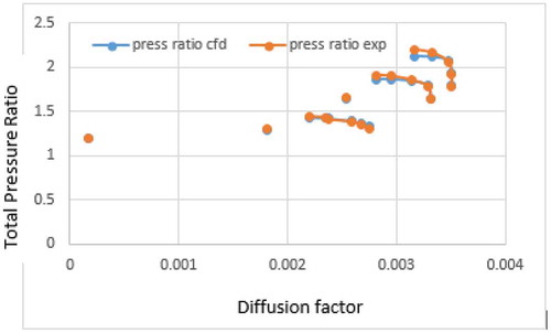
Figure 9. 100% design speed, adiabatic efficiency of rotor 37.
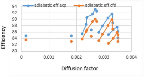
Figure 10. 100% design speed, grid independency check validation of rotor 37 efficiency.
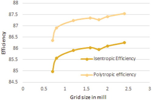
Figure 11. 100% design speed, mass flow rate of rotor 37.
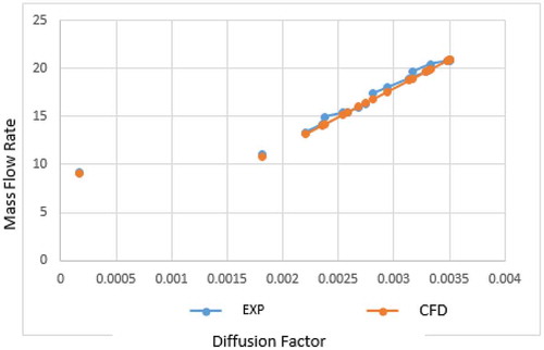
Figure 12. 100% design speed, temperature ratio of rotor 37.
This article gives more emphasis on axial-flow compressor stage, its total pressure ratio and related performance parameters. Report is generated by ANSYS® tool after the completion of numerical analysis with the required convergence limit. The results of this numerical simulation and experimental values are plotted in Figure . The numerical simulation results are higher than the experimental values by ±1.25 % because of the realistic conditions during the conduction of experiments and is minimum for a Mach number of 0.8 and the same has been represented in terms of diffusion factor with respect to the efficiency
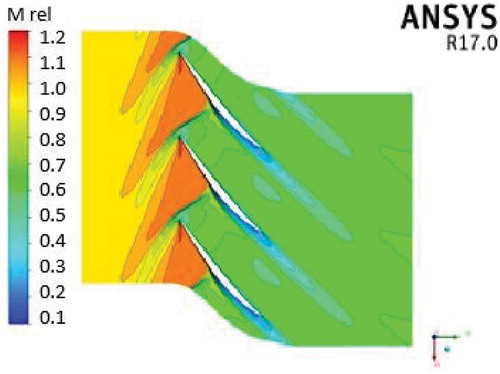
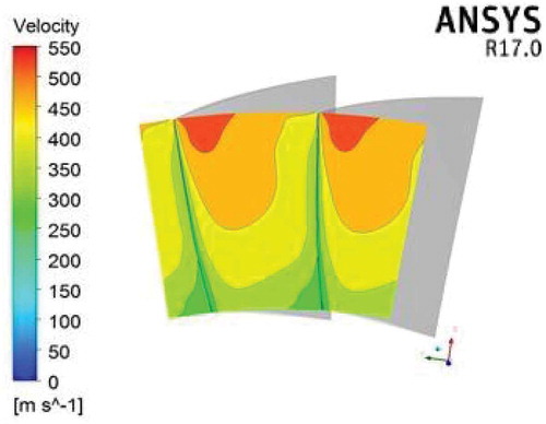
Max efficiency at 100% speed line transonic flow velocity distribution contours at chocked flow, near-stall condition is shown in Figures –1. These are pertaining to velocity distribution across the blade passages for different flow conditions with Mach numbers 0.8, 1.0 and 1.2, respectively. From Figure , it is observed that for Mach number 0.8, a strong shock wave propagated near trailing edge of the rotor blade and slight below the center chord region above the pressure side surface.
Figure 13. Velocity distribution across the stage at Mach 0.8.
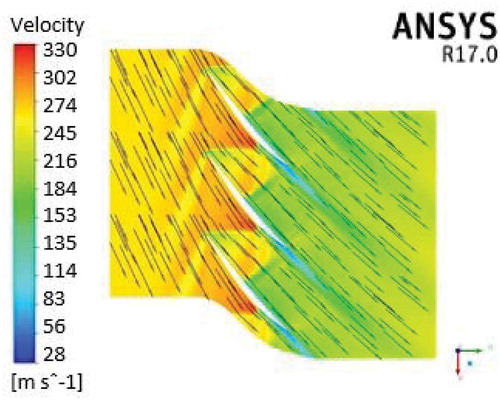
Figure 14. Velocity distribution across the stage at Mach 1.0.
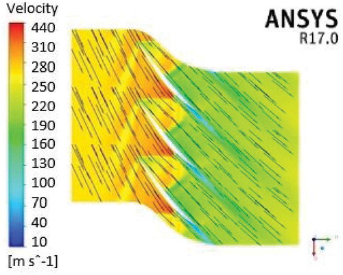
Figure 15. Velocity distribution across the stage at Mach 1.2.
Where as in the stator blade, the flow is smooth and not much flow disturbance is observed. At Mach number 1.0, the strong shock wave is slightly shifted toward the leading edge on the pressure-side surface of the rotor blade as shown in Figure . At Mach number 1.0, also the flow is smooth in the stator blade. The Figure shows the velocity distribution across a stage at Mach number 1.2. In this case, the strong shock wave is shifted toward the leading edge of the rotor blade and further the flow is as usual smooth in the stator blade. In all the three cases, it is very much clear that the occurrence of more energy fluid at the leading edge and less energy fluid at the trailing edge of the rotor blade appears. The difference of energy takes place due to the tip clearance gap, where the leakage of flow is possible. Figure shows the pressure distribution contours for the pressure and suction side of the blade for 50% design speed line at Mach number 1.2.
Figure 16. Pressure distribution across the blade streamwise direction at Mach 08, 1.0 and 1.2.
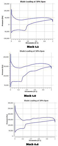
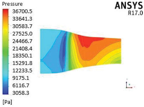
The transonic axial-flow compressor stage pressure distribution is also calculated for different flow conditions. For the Mach number 0.8, the pressure is more near pressure side and suction side of the blade compared to the tip region as shown in Figures and 1. The maximum pressure is noticed at Mach number 0.8 and occurs at pressure side of the blade which is 28,235.8 Pa. Consecutively at Mach number 1.0, the maximum pressure noticed is 33,285.4 Pa and it is also noticed that near the blade, pressure side of the blade flow separation takes place as shown in the Figures and 2. As shown in Fig and 2, the maximum pressure distribution is 36,700.5 Pa both at the suction side and pressure side of the rotor blade for Mach number 1.2.
Figure 17. Pressure distribution on rotor blade suction side at Mach 0.8.

Figure 18. Pressure distribution on rotor blade pressure side at Mach 0.8.
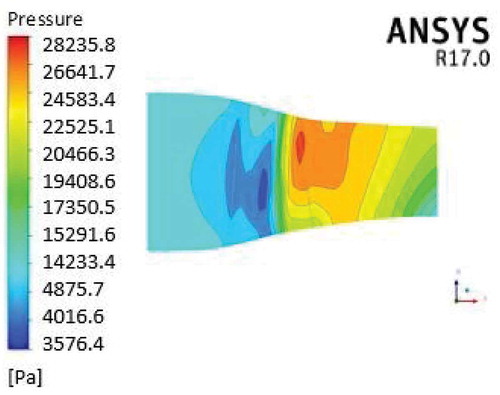
Figure 19. Pressure distribution on rotor blade suction side at Mach 1.0.
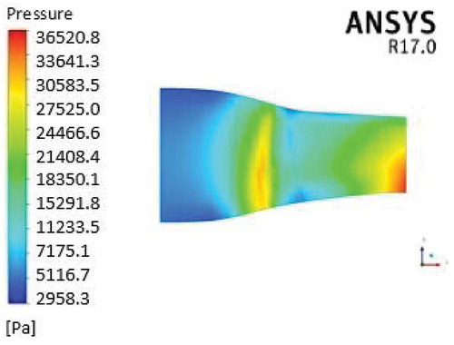
Figure 20. Pressure distribution on rotor blade pressure sides at Mach 1.0.
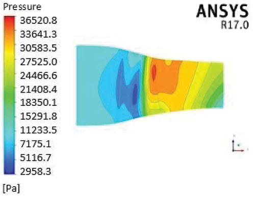
Figure 21. Pressure distribution on rotor blade suction side at Mach 1.2.
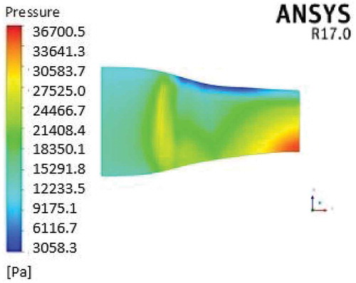
Figure 22. Pressure distribution on rotor blade pressure side at Mach 1.2.
The aerodynamics behavior and flow turbulence effects at different flow conditions on the rotor blade passages are also analyzed to see the distorted effects. At 100% design speed line, relative Mach number distribution especially from rotor to stator blade passages performance has been completed. The same results are also validated with the available literature (Reid & Moore, Citation1978). In this analysis, a few quite interesting points can be made through boundary layer as far as the flow interaction and shock structure is concerned. In the case of Mach number 0.8, the shock is more detached and relatively the flow velocity keeps on diminishing from leading edge passage to trailing edge passage as shown in Figure . At Mach number 1.0 flow condition, the tip vortex is found very strong at the leading edge of the rotor as shown in Figure . It is observed from Figure that the reduction in flow separation after the shock interaction leads to low velocity flow at Mach number 1.2.
Figure 23. Mach number distribution on stage at Mach 0.8.
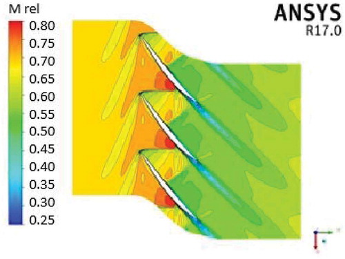
Figure 24. Mach number distribution on stage at Mach 1.0.
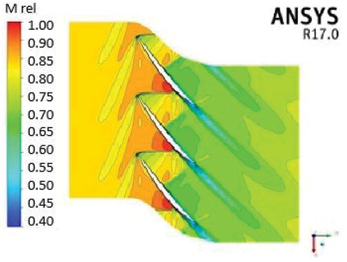
Figure 25. Mach number distribution on stage at Mach 1.2.
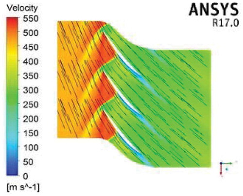
Due to the distortion effect, the blade tip generates air pockets, which is generally termed as “vortex rounds”. This phenomenon happens when the flow reaches from subsonic conditions (Mach number less than 1.0) to transonic conditions (Mach number 0.8–1.2). For better understanding of distortion effects, the three-dimensional flow air pockets formation is also shown in all transonic flow conditions. Figure clearly shows the formation of air pockets near the tip of the blade corners and it is also noticed that the average velocity of these pockets is 216 m/sec. With the increase in flow condition at Mach number 1.0, it is also observed that air pockets velocity increases to 225 m/sec as shown in Figure . At Mach number 1.2, the velocity of air pockets is much higher than 355 m/sec as shown in Figure .
Figure 26. Vortex flow near the tip of the rotor blade at Mach 0.8.
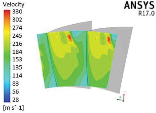
Figure 27. Vortex flow near the tip of the rotor blade at Mach 1.0.
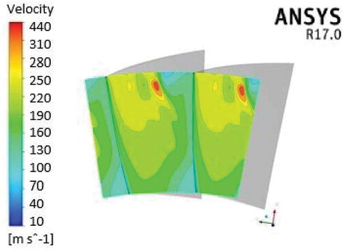
Figure 28. Vortex flow near the tip of the rotor blade at Mach 1.2.
5. Conclusions
Analysis of an axial-flow compressor stage blade passage is presented deliberately. To accomplish this work, National Aeronautics and Space Administration (NASA) Rotor 36 and Stator 37 blade data are taken for simulations, which were implemented by using ANSYS® commercial CFD tool. The axial compressor stage model is created artificially in the software exactly like realistic model taken from the literature to evaluate the distortion effect and overall performance of the stage. The compressor stage model was used to simulate the occurrence of distortion by incorporating different combinations in order to calculate the performance characteristics of stage due to distortion. From the numerical results, it is noticed that the major effect of distortion is the decrease of mass flow rate. Due to the occurrence of the sudden flow disturbance at the suction side portion of the blade, it is noticed that there is a decrease of compressor stage pressure ratio. In this numerical simulation, an attempt is made for different unsteady and non-uniform flow combination to see the flow effect on rotor and stator blade. Due to the development of high kinetic energy in the rotor blade, the flow distortion effect is more on the pressure side of the rotor blade than on suction side of the blade. Through this numerical analysis, it has been brought out noticeably that, in the 100% and 50% speed line, the distortion phenomena is more influencing near the tip axial chord of rotor blade. This distortion effect is much higher at suction surface and even at the spanwise direction of the rotor suction side of the blade.
Additional information
Funding
Notes on contributors
G Srinivas
Srinivas G, Raghunandana K, Satish Shenoy B The group is working on the evaluation and enhancement of the performance of an axial-flow compressor in transonic flow condition, under distorted phenomena. The main objective of the work is to model and simulate a full rotor flow under two specific conditions viz. design and off-design environment with steady-state condition and hence find out the reliability of full annulus flow. The team would like to validate these results with the published experimental data. The flow field that develops inside a transonic compressor rotor is extremely complex and presents many challenges to the compressor designers. They have to deal with concurring flow features such as shock waves, shock/boundary layer interaction and intense secondary flows which induce energy losses and hence reduce the efficiency. Apart from the induced energy losses, the presence of shock waves makes transonic compressors particularly sensitive to variations in blade section design.
Related Research Data
References
- Alone, D. B. , Kumar, S. S. , Thimmaiah, S. M. , Mudipalli, J. R. R. , Pradeep, A. M. , Srinivasan, R. , & Iyengar, V. S. (2016, September). Stability management of high speed axial flow compressor stage through axial extensions of bend skewed casing treatment. Propulsion and Power Research , 5(3), 236–249. doi:10.1016/j.jppr.2016.01.009
- Biollo, R. , & Benini, E. (2013). Recent advances in transonic axial compressor aerodynamics. Progress in Aerospace Sciences , 56, 1–18. doi:10.1016/j.paerosci.2012.05.002
- Daabo, A. M. , Saad Mahmoud, R. K. , Al-Dadah, A. M. , & Al Jubori, A. B. E. (2017). Numerical analysis of small scale axial and radial turbines for solar powered Brayton cycle application. Applied Thermal Engineering , 120, 672–693.
- Dinh, C.-T. , Heo, M.-W. , & Kim, K.-Y. (2015). Aerodynamic performance of transonic axial compressor with a casing groove combined with blade tip injection and ejection. Aerospace Science and Technology , 46, 176–187. doi:10.1016/j.ast.2015.07.006
- Hossein, K. (2017). Parametric study of injector radial penetration on stalling characteristics of a transonic fan. Aerospace Science and Technology , 66, 112–118. doi:10.1016/j.ast.2017.02.020
- Jian, H. , & Hu, W. (2008). Numerical investigation of inlet distortion on an axial flow compressor rotor with circumferential groove casing treatment. Chinese Journal of Aeronautics , 21, 496–505. doi:10.1016/S1000-9361(08)60166-1
- Mao, X. , Liu, B. , & Zhao, H. (2018). Numerical analysis of the circumferential grooves casing treatment in a counter-rotating axial flow compressor. Applied Thermal Engineering , 130, 29–39. doi:10.1016/j.applthermaleng.2017.11.044
- Min, J. B. Duffy, K. P. , Choi, B. B. , Provenza, A. J. , & Kray, N. 2013. “Numerical modeling methodology and experimental study for piezoelectric vibration damping control of rotating composite fan blades.” 11 June
- Mohsen, M. , Owis, F. M. , & Hashim, A. A. (2017). The impact of tandem rotor blades on the performance of transonic axial compressors. Aerospace Science and Technology , 67, 237–248. doi:10.1016/j.ast.2017.04.019
- Poursaeidi, E. , Tafrishi, H. , & Amani, H. (2017). Experimental-numerical investigation for predicting erosion in the first stage of an axial compressor. Powder Technology , 306, 80–87. doi:10.1016/j.powtec.2016.10.057
- Reid, L. , & Moore, R. D. 1978. “Design and overall performance of four highly-loaded, high-speed inlet stages for an advanced high-pressure ratio core compressor,” NASA TP 1337.
- Ren, X. , & Chunwei, G. (2016). A numerical study on the tip clearance in an axial transonic compressor rotor. Applied Thermal Engineering , 103, 282–290. doi:10.1016/j.applthermaleng.2016.04.082
- Shaobing, H. , & Jingjun, Z. (2016). Effect of blade tip winglet on the performance of a highly loaded transonic compressor rotor. Chinese Journal of Aeronautics , 29(3), 653–661. doi:10.1016/j.cja.2016.04.014
- Suder, K. L. , Hathaway, M. D. , Thorp, S. A. , Strazisar, A. J. , & Michelle, B. (2001, January). Bright compressor stability enhancement using discrete tip injection. Journal of Turbomachinery , 123(1), 14 - 23.
- Wang, Z. , Lu, B. , Liu, J. , & Hu, J. (2018). Numerical simulation of unsteady tip clearance flow in a transonic compressor rotor. Aerospace Science and Technology , 72, 193–203.
- Xiaofeng, S. U. N. , Dakun, S. U. N. , & Weiwei, Y. U. (2011). A model to predict stall inception of transonic axial flow fan/ compressors. Chinese Journal of Aeronautics , 24, 687–700.
- Xuemin, Y. , Zhang, J. , & Chunxi, L. (2017). Effect of blade tip pattern on performance of a twin-stage variablepitch axial fan. Energy , 126, 535e–563. doi:10.1016/j.energy.2017.03.057
- Zhihui, L. , & Liu, Y. (2017). Blade-end treatment for axial compressors based on optimization method. Energy , 126, 217e–230.
- Zhou, X. , Zhao, Q. , Cui, W. , & Jianzhong, X. (2017). Investigation on axial effect of slot casing treatment in a transonic compressor. Applied Thermal Engineering , 126, 53–69. doi:10.1016/j.applthermaleng.2017.07.165