
 ?Mathematical formulae have been encoded as MathML and are displayed in this HTML version using MathJax in order to improve their display. Uncheck the box to turn MathJax off. This feature requires Javascript. Click on a formula to zoom.
Abstract
A home delivery logistics network is able to deliver goods to the home in reusable smart-boxes transported by Driverless Delivery Vehicles (DDV). Since the delivery vehicle does not have a human driver, in this case, how to deliver, pick up and rearrange smart-boxes into the Driverless Delivery Vehicles efficiently during routing?
In this paper, we combine the results of works on the high density storage system and the results of works which solve sub-optimally the (n2-1)-puzzle, for to propose a new “Rearrangement While Routing” strategy for a Driverless Delivery Vehicle based on “snake-line arrangement” and “Pull–Push Rearrangement”. Furthermore, we compare our strategy with three other strategies arrangement based on Manhattan Distance, Number of moves and a Hybrid arrangement combined both Manhattan Distance and Number of moves. The results show that the proposed “Pull–Push Rearrangement” is most efficient in terms number of moves and displacements.
PUBLIC INTEREST STATEMENT
In this work, we formalize the arranging smart-boxes into Driverless Delivery Vehicle (DDV). The DDV is an autonomous car without human-driver. It is able to attain the destination to deliver a customer using satellite positioning and guidance means. However, it is necessary the delivery and the return of smart-boxes is also done in an autonomous and automatic way. In this case how to arrange and rearrange the smart-boxes in the autonomous car to minimize the movements of the smart-boxes? Smart boxes are sequenced in puzzle form to make the maximum of the available space in the autonomous car. The aim of smart-boxes arrangement is to find the trade-off between space exploitation and access rapidity is considered. To do this the smarts-boxes arrangement is based on a continuous line (called snake-line) which allows to move the boxes in a continuous way with the minimum movement of neighboring boxes. This allows customers to be delivered with automated systems and without human intervention.
1. Introduction
Several internretailers claim that it is better for the consumer to shop online and have their goods delivered to the home than to travel to the shops. Especially for small purchases and non-food items, such as books, clothes or sports goods and household items [3]. Furthermore, two important points affect negatively the effectiveness of “home delivery”, namely Failed delivery: Edwards et al. (Citation2009) indicated a range between 2% and 30%, depending on the carriers’ policies for dealing with “no-one-at-home” and Returns: Edwards et al. (Citation2009) mentioned a range between 25% and 30% of all non-food goods bought online is returned.
The Physical Intern(PI or π) is a major supply chain principle that has the potential for sustaining a “home delivery” challenge, by changing the way to handle, store, package and transport goods across the supply chain (Montreuil, Citation2013; Ballot, Gobet, & Montreuil, Citation2012; Montreuil et al., Citation2013). For this way, two key technologies are necessary: DDV and High-Density Storage (HDS) system able of automatic loading and unloading (Gue, Uludag, & Furmans, Citation2012).
In an open transport network as Physical Internshipments, goods will go through the destination by intermediate hubs in the network, namely PI-Hub (π-Hub). The PI-hub place, load and unload “Smart-Boxes” (Graf & Kapplmüller, Citation2015) in the DDV. Orders not delivered are returned to the PI-Hub for reuse and stored in the PI-Hub.
DDV is an autonomous cars or vehicles capable of sensing their environment and navigating without any human input, they are being envisaged as a key transportation mode of the future. For example, Google, Apple, and Uber, are searching on autonomous driving technologies. Google is preparing a fully self-driving prototype that eliminates completely the driver. DDV is a solution to bring the last mile (Rowley et al., Citation2018). In this case, the DDV moves from one Delivery-Pickup Point (DDP) to another using a geographical positioning system (GPS). Figure ) presents an example for a route taken by the DDV that starts from the “PI-Hub 0” and then visits the customers 1, 2 …8. At each Delivery/Pickup Point (DPP), the DDV delivers the new “Smart-Box” and pick up the return “Smart-Box”.
Figure 1. (a). Delivery of height orders to a home and return of “Smart-boxes”. (b). Side view and Top view of Driverless Delivery Vehicle (DDV)
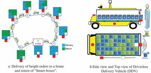
The customer is guided by a “voice” which provides the instructions to follow when unloading/loading “Smart-Boxes” (See Figure )). The centralized control task is to re-arrange “Smart-Boxes” (while driving between two Delivery/Pickup Points) on the grid into a desired goal state. The structure for sliding the “Smart-Boxes” is constituted a rectangular grid (5 × 10 cells) with square conveyor modules (Figure )). Each module (called “Flex-conveyor” (Ballot et al., Citation2012): is a “Right-Angle-Transfer” able to slide the “Smart-Box” in the four directions (Left (L), Right (R), Up (U), and Down (D)) if the neighboring location is empty. The idea is derived from the 15-puzzle shown in Figure ) (Gue & Kim, Citation2007).
Figure 2. (a) Flex-conveyor (b) Fifteen-Puzzle. (c) Smart-Box
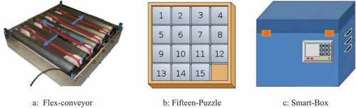
The “Smart-Box” (Figure )) is built as Smart, capable of communicating effectively with its environment and make decisions relevant to its own destiny (Graf & Kapplmüller, Citation2015). Safe, User-Friendly and vandal-proof: to be opened only by authorized persons, ecological, reusable and recyclable (Harald, Graf, Hoertenhuber, Widmann, & Stadlmann, Citation2016). The following table (Table ) shows the attributes of smart-boxes.
Table 1. Attributes of a “Smart-Box”
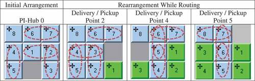
The task of “Rearrange While Routing” sequence is to find a succession of valid moves, which transforms the initial configuration into the goal configuration (between Delivery/Pickup Point (i) and the next Delivery/Pickup Point (i + 1)) as shown in Figure ). In this case, how to initially arrange the smart-boxes into the DDV to avoid unnecessary displacements? How to optimize the successively rearrangement of “smart-boxes” in the DDV while-driving between two customers destination?
After the description of constitution of the DDV and the PI-Hub, we descript in the next section the related works on different routing control strategies for a High-Density-Systems (HDS) based on a Puzzle-Based-Storage (PBS). The problem statement is developed in Section three. Thereafter, the “arrangement and rearrangement strategies” are discussed in Section four. Section five evaluates the experiment results. Conclusions of the study and future work are made in Section six.
2. Literature review
The moving and sequencing goods through Puzzle-Based-Storage (PBS) systems are divided into two families: PBS with unit-sized conveyors and Puzzle-Based-Storage (PBS) with Automated Guided Vehicles (AGVs). In this article, we focus only on state-of-art from the Puzzle-Based-Storage (PBS) with unit-size conveyors because, that represents our case study.
To our knowledge, Gue (Citation2006) is the first to have developed a new concept based on the famous Sam Loyd’s puzzle game the “15- puzzle”: a Very High Density Storage for physical goods. He describes algorithm to densely fill rectangular storage spaces, subject to a constraint on the number of interfering items. He also proved an upper bound on the storage density for any rectangular space, including traditional warehouses.
Gue and Kim (Citation2007) follow the idea of Gue (Citation2006) and develop algorithm based on puzzle moves for optimal retrieval path systems with one fixed Input/Output Point (I/O-Point) and they compare the experimental results for the configurations with multiple empty locations with traditional aisle-based designs found in warehousing systems. They note that puzzle-based systems have higher retrieval times than aisle-based systems, if the desired storage density is minus than 90%.
Taylor and Gue (Citation2009) extend the work of Gue and Kim (Citation2007) by analyzing the design and performance in multi-level Puzzle-Based Storage Systems and identifying potentials for implementation. They study the effect of the distribution of escorts in the puzzle-based system. They study three locations of escorts: 1) near the Input/Output Point (located at a lower left corner of the grid), 2) along the diagonal from lower left to upper right, and 3) randomly on the grid. They prove that when the number of escorts is above 25%, having the escorts along the diagonal always outperforms the other strategies. They compare the performance with a storage based on an ABC policy, in which, random placement for the escorts is the best option.
Kota, Taylor, and Gue (Citation2015) extend the model of Gue and Kim (Citation2007) by letting the single escort to be randomly located in the grid. They also develop an Integer Programming model for the system with two escorts, one near the Input/Output Point (I/O-Point) and one randomly placed on the grid.
Furmans, Nobbe, and Schwab (Citation2011) extend the algorithm by Gue and Kim (Citation2007) and present analytical retrieval times for a system with one AGV, one escort, one requested load, and variable Input/Output Point (I/O-Point). The authors present an analysis of different positions for the Input/Output Point (I/O-Point) and find that it should best be located in the middle of the longer side of the grid for the considered configuration assumptions.
Gue and Furmans (Citation2011) propose a decentralized control for Puzzle-Based Storage Systems based on a Virtual Aisle Strategy with conveyors. In contrast to the puzzle strategy, there is not one Input/Output Point (I/O-Point), but all cells in the front row are output points in the system, and a requested load can leave the system at any of those cells. The advantages of a decentralized control for this system are a higher robustness to breakdowns and a bigger flexibility for system changes (e.g. additional cells).
Alfieri al. (Citation2012) present an algorithm for GridFlow 2D with multiple escort systems: one requested load, one AGV, and one fixed Input/Output Point (I/O-Point). The algorithm transfers the algorithm by Gue and Kim (Citation2007) using the same load moves but enabling load movement by an AGV, instead of conveyors. The authors present additional throughput data of case simulations with this algorithm.
Furmans, Gue, and Seibold (Citation2013) proposed a GridFlow 2D storage system based on multiple autonomous conveyor modules to react to fluctuating processing volumes and layout changes. The authors develop algorithm able to react to occurring failures in neighboring modules. Through a Monte Carlo experiment using a discrete event, the simulation proved that the algorithm prevents system deadlock.
Kota et al. (Citation2015) develop a puzzle-based storage system a closed-form expression for the retrieval time in the grid with randomly located escorts. They propose a heuristic solution which gives a near optimal solution.
Zaerpour et al. (Citation2017) propose a two-class-based storage policy for a live-cube system. They derive closed-form formulas to calculate the expected retrieval time of the system. They conclude that their proposed storage policy can improve the average response time of the system up to 55% compared to the random storage policy, and up to 22% compared to the cuboids two-class-based storage policy.
Zaerpour, Yu, and de Koster (Citation2017) investigate a multi-tier puzzle-based (live-cube) storage system. They assume sufficient escorts are available at each level so that a virtual aisle can be created (minimum number of escorts is the maximum of the rows and columns in the system). They use traditional methods for the aisle-based system and derive a closed-form formula for expected retrieval time.
Xu, Gong, Fan, Shen, and Zou (Citation2017) study a 3D storage system with high space utilization. They analyze single-command cycles with dual-command cycles by comparing the travel time and validate analytical models by simulation. The results show that the dual-command outperforms the single-command in terms of cycle time.
Mirzaei and De Koster et al. (Citation2017) propose retrieving multiple items simultaneously. They derive the optimal retrieval time for double-item and triple-item retrieval using enumeration. They propose a heuristic algorithm for more than three simultaneous item retrievals. Their shows that double-item retrieval reduces the storage/retrieval time by on average 17% compared to sequential retrieval. Savings can be further increased by performing multi-item retrievals.
The entire literature review on the Puzzle-Based Storage system treats the System Analysis, Design Optimization or Operations Planning and Control (Azadeh, de Koster, & Roy, Citation2017), but does not address the rearrangement as we envisage it in our work. The following section sets out the problem statement.
3. Problem statement
Rearranging the “Smart-Boxes” in the DDV can be assimilated as Sliding-Tiles Puzzle (STP) or Sliding-Block Puzzle (SBP) problem. The task in the puzzle is to rearrange (n x m −1) tiles on the grid of the n x m to the desired goal configuration. The (n x m)-puzzle can be presented by a four-connected grind using one vacant vertex (one vacant position). The (n2–1)-puzzle is a special case of the more general problem of Sliding-Tile Puzzle. Therefore, we consider a “Smart-Box” as a “tile”.
In this section, we propose a mathematical formulation for this statement and develop in the next section our routing approach.
Sets of tiles can be arranged on a grid of the size where each tile is located in one of the cells on the grid with η ∈ ℕ and
∈ ℕ. This model can be represented by a graph.
Lan undirected graph and l
be a sof tiles. The arrangement of tiles in
will be described by a uniquely invertible function:
.
The dynamicity of the graph model assumes a discrete time unit steps and represented by Σ = [G = (V, E), T, α0, αi] where (α0, αi) define, respectively, initial arrangement and rearrangement i-th time step of a sets of tiles T in the graph G. the rearrangement configuration must following the conditions: ,r
The arrangement of tiles can be changed through moves. Four types of moves are authorized: left, right, up, and down to slide a tile from its original cell to the adjacent vacant cell. Only left move is defined formally; right, up, and down moves are analogous.
3.1. Arrangement and rearrangement strategies
In the classical resolution of -puzzle, the initial arrangement is given randomly (knowing that there are n! possibilities of placements) and the final position is more important (succession of the numbering of the tiles) (See Figure ). The majority of the state-of-art focuses on the solving the
-puzzle optimally, by using fast computation-time algorithms and less memory space.
Figure 3. N-puzzle model
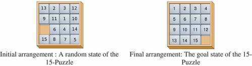
Our “goal state” is not the succession of numbered tiles (as in Figure ), but rather to move from an initial configuration to an intermediate (or finale) configuration with the minimum of moves. In our case, the initial arrangement and rearrangement strongly influences on the performance of the PI-DDV. Furthermore, the initial arrangement and rearrangement should be simple to automate and easily realizable in real-life. The following describes in detail the solutions approaches.
3.2. Initial arrangement
As mentioned above, there are possibilities of arrangement in a (η x η)-puzzle. In this case, how to choose a strategy of arrangement and rearrangement of the tiles? We have chosen logic based on the “metric” characteristics of a puzzle: the distance of a tile to Input/Output Point (I/O Point), the number of moves of the tiles to attain I/O Point, hybrid arrangement combining the both first and the positioning according to the “snake-line” (note: all these proposed arrangements are among the possible arrangements).
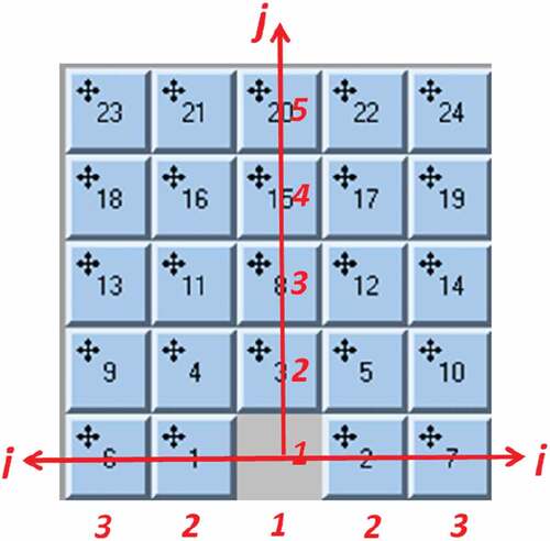
3.2.1. Manhattan distance arrangement
The minimum distance for a tile to move from its current location to the targlocation can be described with the so-called Manhattan Distance (MD) (Black, Citation2006). This distance is the sum of the vertical and horizontal distance from the box to the targlocation. The goal of the initial arrangement based on Manhattan Distance is to place the tiles in order to reduce the distance from I/O point. For each route, the distance to travel is equal to the Manhattan distance. Since a tile can only be moved along the four cardinal directions and not diagonally, the Manhattan distance is admissible. Comparing the Manhattan Distance of different moves can be a good indication of which move is the best.
Figure shows, the tiles are located over a mesh model based on the Manhattan distance.
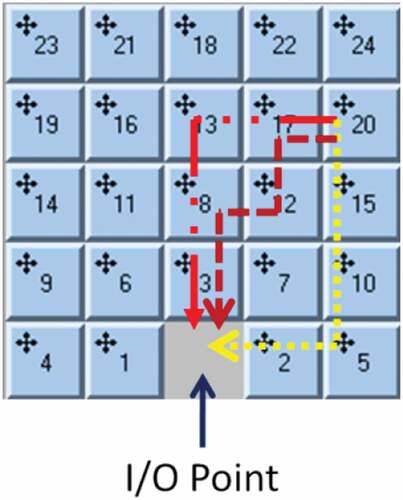
Figure 4. Arrangement according to Manhattan Distance. They are three different ways for a tile number 20 to reach its targposition (I/O Point), all in the same minimum Manhattan Distance (MD = 5)
3.2.2. Number of moves arrangement
According to Gue and Kim (Citation2007) the minimum number of moves to retrieve an item in location (i, j) to attain I/O point is (see Figure ):
For all (i, j) Integer > 1, where (i) is the row and (j) is the column.
Figure 5. I/O point is located at (,
) = (1, 1) Tile number 19 is located at (
,
) = (3, 4).
3.2.3. Hybrid arrangement
The hybrid arrangement is a combination of the first two strategies. The order of tiles placement is in the ascending order of the multiplication result between the Manhattan distance and the number of movements.
3.2.4. Snake-line
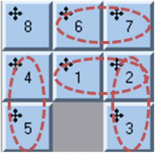
The basic idea is borrowed from Surynek and Michalík (Citation2016), who (for other reasons) proves that moving tiles jointly in snakes-lines Surynek and Michalík (Citation2017) is more efficient for reduction of the total number of moves generated by on-line algorithms for the -puzzle Surynek and Michalík (Citation2016). In our work, we use the “snake-line” arrangement to minimize the number of movements during the “Delivery” phase. Thus, a connection is made between the tiles which follow each other during the initial arrangement and other connection links are made as a function of the positions of the tiles during the rearrangement during the routing of the DDV.
We define the “snake” function as follows:
(1) Two tiles can connect, to form a snake, if and only if their numbers follow one another.
(2) Snakes can connect in them, to form a longer snake, if and only if the “tail” of a snake can connect to the “head” of another snake.
(3) The length of the “snake” is defined by the number of connected tiles that compose it.
(4) The minimum length of a snake shall be at least two tiles.
(5) Only the tile to be delivered takes the role of “puller”.
Figure shows an example of connections at the initial arrangement stage (PI-Hub 0).
Figure 6. Connected Tiles. Initial Arrangement at PI-Hub 0: Tiles 1, 2 and 3 form a first “snake”, tiles 4 and 5 a second “snake” and the third snake is formed by tiles 6 and 7. Tile 8 is isolated (in this configuration)
We define a number of movements made by a snake during the delivery phase as following:
: The number of connections throughout the visit (1 to
).
: The number of tiles of each connection (1 to
).
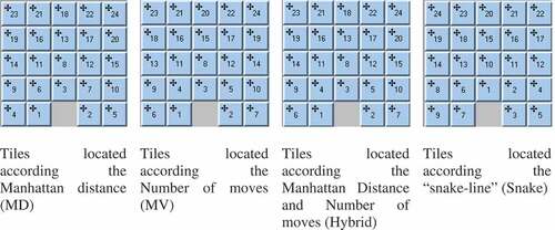
The differentiation between the locations is visible from a puzzle size 5 (5x5-puzzle). The following figures illustrate the different “initial arrangement” for 5x5-puzzle. We choose as the numbering convention: when the tiles have the same weight, begin to number the bottom line first before moving to the top line in ascending order of numbering. For example, in the Manhattan-based location, tiles 4, 5, 6, 7 and 8 have the same Manhattan Distance from I/O point (MD = 2). In this case, we place tiles 4 and 5 on line 1, tiles 6 and 7 on line 2 and tile 8 on line 3 (Figure ).
Figure 7. Different initial rearrangement according Manhattan distance (MD), Number of moves (MV), Hybrid rearrangement and rearrangement in “snake-line”
3.3. Rearrangement while routing
After the initial arrangement, from the PI-Hub, it is now necessary to rearrange the tiles according to the route of destination. The tiles must reorganize autonomously while the DDV is in routing to the next destination. The “Rearrangement While Routing” is to move tiles from an initial situation to a pre-specified new arrangement. This rearrangement is done using a -puzzle solver for initial arrangements based on the “metric” characteristics of a puzzle. In the case of the arrangement based on the “snake-line”, we propose a new “Pull–Push” sequence. The following describes in detail the two approaches.
3.3.1. (n*m–1)-puzzle solver
From a rearrangement, we define the desired position of the tile
to be delivered, the
-puzzle solver based on the A* search algorithm (Hart, Nilsson, & Raphael, Citation1968) proposes a new rearrangement
for the targstate. The figure above shows an example: the initial rearrangement to the DPP 3 (Figure )), the objective position for tile 4 (
) to arrive at the DPP 4 (Figure )) and the result obtained by the
-puzzle solver at DPP 4 (Figure )).
Figure 8. (a). Initial rearrangement at Delivery Pickup Point 3 (Ri). (b). Target state for delivery tile 4 (ti+1). (c). 5 moves for delivery tile 4 according to puzzle-solver (Ri+1). (d). Push-1: 1 Left move for return tile 4
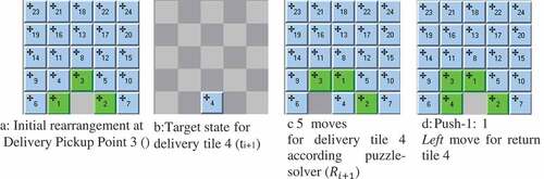
The return phase is based on Push-1 where the tile to be returned moves only one step relative to I/O points to the right, left or up (Figure )).
3.3.2. Pull–push moves
In the world of games based on the puzzle (Sokoban, Rush Hour, Atomix or others for example) in which the player can pull or/and push tiles at a time, or the moved-tiles slide until hitting an immovable tile, the resolution of these problems is PSPACE-complete or NP-hard (Pereira, Ritt, & Buriol, Citation2016). Our contribution is not to study the complexity of solving this class of problems, or if the pull–push-tiles puzzle is intractable or not. However, our objective is rather to adapt the principles and observations to a practical case of real-life.
In the proposed “Pull–Push” moves, the “Pull-moves” performs during the “Delivery” phase and the “Push-moves” during the “Pickup” phase. The “Pull” operation consists of moving all the tiles serially connected (like a snake) without moving the other tiles: unconnected or the returned tiles (in green color).
Figure shows the different connections made during the initial arrangement phase and the other connections during the progresses routing DDV. Between PI-Hub 0 and DPP 2, the tiles 4–8 remain immobile, because the connection between the tiles 3 and 4 is not yet effective.
Figure 9. Iterative connections from PI-Hub to Delivery/Pickup point 5
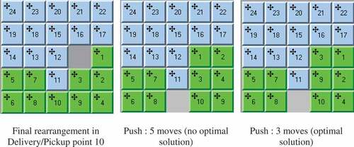
The “Push” operation rearranges the returned tiles (green) to empty the I/O point. The Push operation pushes the tiles one step (one vertex) toward its target position along the path. If the next vertex on the path is occupied by other tiles, Push tries to free this vertex by moving the tiles out of it. During the Push phase in the example above, two options are available to us, as shown in Figure . The algorithm chooses the best option, namely the minimum displacement.
Figure 10. Two feasible rearrangements (5 moves versus 3 moves)
Returns are not connected to each other and are processed individually. Otherwise, the original way of placing tiles individually is used.
The Table below summarizes these different strategies:
Table 2. Initiatial arrangement and rearrangement for different strategies
3.4. Block moving
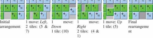
The DVD is an automated vehicle. Therefore, if the tiles are in line, the tiles move simultaneously in block by time-unit (Gue et al. (Citation2012). Moving by block is possible as long as the tiles are in line. Figure shows the move of the tiles from initial arrangement to final rearrangement: the total number of displacements is 5 moves, and the number of moved tiles is 5.
Figure 11. In the DDV, it is possible to move more than one tile at each time-unit, if the tiles are in line. The tiles (5 & 7) and (4 & 1) move in line
4. Experimental results
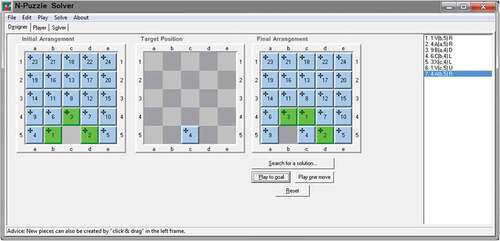
Generally speaking, this study is an “engineering application” and use a “numerical optimization technique” (Abo-Hammour, Arqub, Alsmadi, Momani, & Alsaedi, Citation2014). In fact, numerical methods are appropriate in engineering applications while of the simplicity with which numerical techniques can be used in combination with modern high-speed digital computers (Arqub & Abo-Hammour, Citation2014) (Arqub et al. Citation2016). An experimental evaluation is essential to verify performance of our proposed “Pull–Push”. This section presents experimental validation for the algorithms introduced in this paper. We have implemented our algorithms in C++. It has been compiled using the Microsoft Visual Studio 2008 C++ compiler. We used a PC with an Intel Core i7 930 processor with 12 GB of main memory for the experiments. Figure shows the Graphical User Interface GUI of the application.
Figure 12. Graphical User Interface GUI
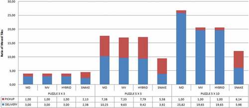
We measure the performance by two indicators: and
RTMT represents the fraction between the number of total moved tiles by the number of calculated moves in the delivery and pickup phases. RT represents the quotient between the number of moved tiles and the number of tiles in the puzzle.
We compare four initial arrangement strategies, the first based on the placement of the tile according to the length of the MD up to I/O point, the second based on the placement according to the number of movement to be performed by each tile for reaching I/O point. The third strategy is a hybrid compromise between the first two. Finally, the last strategy based on the arrangement according to “snake-line”, this for three different puzzle sizes: 3 x 3, 5 × 5 and 5 × 10 how represents our real case.
Whatever the size of the puzzle, the strategy based on the initial arrangement according to “snake-line” offers a better performance, it allows to reduce approximately 40% to 60% the total number of moves. Furthermore, the strategy based on the MD is better than the MV and Hybrid. This is observable in Figure .
Figure 13. Ratio of moved tiles
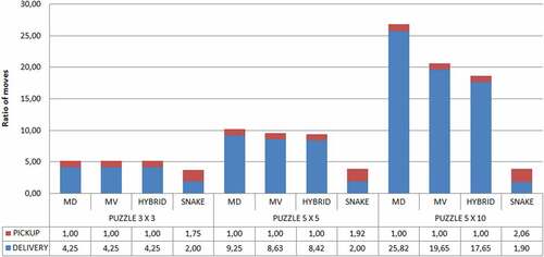
We observe, moreover, that the performance of the arrangement according to “snake-line” increases with the size of the “puzzle”. This is explained by the fact that the snake-line brings a consistent reduction of “total number of moved tiles” (Figure ).
Figure 14. Ratio of number of moves
5. Conclusion
In this paper, we presented a new “Rearrangement While Routing” strategy for a DDV based on “snake-line arrangement” and “Pull–Push Rearrangement”. Furthermore, we compare our strategy with three other strategies arrangement based on Manhattan Distance, Number of moves and a Hybrid arrangement combined both Manhattan Distance and Number of moves. We have shown that the proposed “Pull–Push Rearrangement” is most efficient in terms number of moves and displacements. This approach reduces the number of displacement for an item from the initial position to the I/O point and the number to move neighbors’ items.
The next step is to analyze the influence of the stacked storage grids on multiple levels of 3D storage with an elevator and with always one I/O point. Another extension from the scientific research could be to develop a genetic algorithm (GA) based on “tile motion on graphs”.
Additional information
Funding
Notes on contributors
Samir Tetouani
Samir Tetouani is an engineer of industrial engineering. He graduated in 1995 with a Bachelor’s Degree in Mechanical Engineering and received his Master from the School of Industrial & Systems Engineering at ENSAM Paris. Actually, he is Assistant Professor in the Information Management System Department at the ESITH. His scientific research focuses on Artificial Intelligence and Multi-Agent Systems, including applications to real-time environments, such as Physical Internand Industry 4.0.
References
- Abo-Hammour, Z., Arqub, O. A., Alsmadi, O., Momani, S., & Alsaedi, A. (2014). An optimization algorithm for solving systems of singular boundary value problems. Applied Mathematics & Information Sciences, 8(6), 2809. doi:10.12785/amis/080617
- Alfieri, A., Cantamessa, M., Monchiero, A., & Montagna, F. (2012). Heuristics for puzzle-based storage systems driven by a limited sof automated guided vehicles. Journal of Intelligent Manufacturing, 23(5), 1695–14.
- Arqub, O. A., Mohammed, A. S., Momani, S., & Hayat, T. (2016). Numerical solutions of fuzzy differential equations using reproducing kernel Hilbert space method. Soft Computing, 20(8), 3283–3302. doi:10.1007/s00500-015-1707-4
- Arqub, O. A., & Abo-Hammour, Z. (2014). Numerical solution of systems of second-order boundary value problems using continuous genetic algorithm. Information Sciences, 279, 396–415. doi:10.1016/j.ins.2014.03.128
- Azadeh, K., de Koster, M. B. M., & Roy, D. (2017). Robotized warehouse systems: Developments and research opportunities. Social Science Research Network.
- Ballot, E., Gobet, O., & Montreuil, B. (2012). Physical internenabled open hub network design for distributed networked operations. In Service orientation in holonic and multi-agent manufacturing control (pp. 279–292). Springer.
- Black, P. E. (2006). Manhattan distance . Dictionary of Algorithms and Data Structures, 18, 2012.
- Edwards, J. (2009). The impact of failed home deliveries on carbon emissions: Are collection/delivery points environmentally-friendly alternatives? 14th Annual Logistics Research Network Conference (p. M117).
- Furmans, K., Gue, K. R., & Seibold, Z. (2013). Optimization of failure behavior of a decentralized high-density 2D storage system. Dynamics in Logistics, Springer, 415–425.
- Furmans, K., Nobbe, C., & Schwab, M. (2011). Future of material handling–Modular, flexible and efficient. IEEE/RSJ International Conference on Intelligent Robots and Systems.
- Graf, H.-C., & Kapplmüller, H. (2015). smartBOX”-A business concept towards the physical internet. Business Logistics Modern Management.
- Gue, K. R. (2006). Very high density storage systems . IIE Transactions, 38(1), 79–90. doi:10.1080/07408170500247352
- Gue, K. R., & Furmans, K. (2011). Decentralized control in a grid-based storage system, In IIE Annual Conference, Proceedings (p. 1).
- Gue, K. R., & Kim, B. S. (2007). Puzzle-based storage systems. Naval Research Logistics, 54(5), 556–567.
- Gue, K. R., Uludag, O., & Furmans, K. (2012). A high-density system for carton sequencing. Proceedings of the international material handling research colloquium.
- Harald, K., Graf, H., Hoertenhuber, S., Widmann, R., & Stadlmann, B. (2016). SmartBox–An Austrian PI solution leading to small loads mobility 4.0. 3rd international physical internconference, Atlanta, USA.
- Hart, P. E., Nilsson, N. J., & Raphael, B. (1968). A formal basis for the heuristic determination of minimum cost paths. IEEE Transactions on Systems Science and Cybernetics, 4(2), 100–107. doi:10.1109/TSSC.1968.300136
- Kota, V. R., Taylor, D., & Gue, K. R. (2015). Retrieval time performance in puzzle-based storage systems. Journal of Manufacturing Technology Management, 26(4), 582–602. doi:10.1108/JMTM-08-2013-0109
- Mirzaei, M., De Koster, R. B., Zaerpour, N. (2017). Modelling load retrievals in puzzle-based storage systems. International Journal of Production Research, 1–13.
- Montreuil, B. (2013). Physical InternManifesto, v1. 10,(Original v1. 0, 2009).
- Montreuil, B., Meller, R. D., & Ballot, E. (2013). Physical internFoundations. Service Orientation in Holonic and Multi Agent Manufacturing and Robotics, 472, 151–166.
- Pereira, A. G., Ritt, M., & Buriol, L. S. (2016). Pull and PushPull are PSPACE-complete. Theoretical Computer Science, 628, 50–61. doi:10.1016/j.tcs.2016.03.012
- Rowley, J., Liu, A., Sandry, S., Gross, J., Salvador, M., Anton, C., & Fleming, C. (2018, April). Examining the driverless future: An analysis of human-caused vehicle accidents and development of an autonomous vehicle communication testbed. Systems and Information Engineering Design Symposium (SIEDS) (pp. 58–63). IEEE.
- Surynek, P., & Michalík, P. (2016). An improved sub-optimal algorithm for solving-puzzle.
- Surynek, P., & Michalík, P. (2017). Joint Movement of Pebbles in Solving the (N2-1)-Puzzle and its Applications in Cooperative Path-Finding:(JAAMAS). Proceedings of the 16th Conference on Autonomous Agents and MultiAgent Systems (p. 856‑857).
- Taylor, G. D., & Gue, K. R. (2009). Design and performance of multi-level puzzle-based storage systems. Proceedings of the 2009 International Conference on Value Chain Sustainability.
- Xu, X., Gong, Y., Fan, X., Shen, G., & Zou, B. (2017, août). Travel-time model of dual-command cycles in a 3D compact AS/RS with lower mid-point I/O dwell point policy. International Journal of Production Research, 1–22.
- Zaerpour, N., Yu, Y., & de Koster, R. (2015). Small is beautiful: A framework for evaluating and optimizing live-cube compact storage systems. Transportation Science, 51(1), 34–51.
- Zaerpour, N., Yu, Y., & de Koster, R. B. (2017). Response time analysis of a live-cube compact storage system with two storage classes. IISE Transcation, 49(5), 461–480.