
 ?Mathematical formulae have been encoded as MathML and are displayed in this HTML version using MathJax in order to improve their display. Uncheck the box to turn MathJax off. This feature requires Javascript. Click on a formula to zoom.
Abstract
The optimization of gears is crucial to the development of energy efficient mechanical systems. Weight, volume and power output are major objectives dependent on reduced inertia of rotary, mobile systems and losses in power transmission. In the present work, an extended version of an optimal weight design problem available in literature is investigated using multi-objective teaching and learning-based optimization (MOTLBO). Four design cases differentiated by variable ranges and sets were formulated based on an optimal weight design problem in literature. Power input and contact ratio variables were added to the design problem formulation which was investigated by previous authors as a single objective minimum weight problem. The generated Pareto frontiers were also investigated using decision-making methods viz. Linear Programming for Multidimensional Analysis of Preference (LINMAP), Technique for Order of Preference by Similarity to Ideal Solution (TOPSIS). Results obtained reflect the trade-off effects of multiple objectives by increase in optimal weight value as compared to previous studies. The results also highlight the importance of design preference articulation by reflecting on minimum possible results which were better than some obtained in literature.
PUBLIC INTEREST STATEMENT
This research displays and explores the power of computation, nature inspired and advanced algorithms in solving complex engineering problems. In this era reduction of energy consumption, and increased efficiency are key objectives which are often competing. The main quest in any decision is to find the best compromise amongst numerous objectives. This research work also highlights this challenge in todays engineering problems and how computer tools can enhance problem solving.
Competing Interest
The authors declare no conflict of interest.
1. Introduction
Gears are key machine elements in power or drivetrain transmission systems since they link prime movers to driven loads. The efficiency of these systems has a great influence on machine assembly and operational costs. In engineering design, the optimization of gear systems is an important area of study as evidenced by the numerous research studies available in literature (Hofstetter, Lechleitner, Hirz, Gintzel, & Schmidhofer, Citation2018; Maputi & Arora, Citation2019; Miler, Žeželj, Lončar, & Vučković, Citation2018). The increasing need for energy and cost-efficient mechanical transmission systems has contributed to the popularization of optimization methods in engineering design. Notably, gear optimization has been investigated since the dawn of analytical methods and has largely remained a topic of keen interest amongst researchers. With the advancement in optimization, numerous researchers have applied such techniques to investigate various gear design problems.
There are numerous types of gears viz. spur, helical, worm, straight and spiral bevel gears which have been investigated in the literature. Zolfaghari, Goharimanesh, and Akbari (Citation2017) focused on minimizing the volume of a straight bevel gear by using an approximating formula for the frustum of a cone to determine volume. In this study, an analytical method known as AGMA 2001-D-04 (American Gear Manufacturers Association) and an evolutionary algorithm, Simulated Annealing (SA) were applied with improved results obtained using the latter. The worm-wheel gear system was investigated by Mogal and Wakchaure, (Citation2013) while applying a multi-objective formulation to investigate three parameters using a genetic algorithm. Spur and helical gears have been investigated extensively as single and multi-objective problem formulations in literature.
Rai et al. (Citation2018) investigated volume minimization for a helical gear system by setting geometric parameters and profile shift coefficients as variables.
Gear systems may have single or multiple stages depending on application, power, torque and speed ratio requirements. A two-stage gear system was investigated by Sanghvi et al. (Citation2014) employing NSGA-II to optimize load carrying capacity and volume simultaneously. Gear systems, in some cases can be both multi-speed and multi-stage as shown in a research done by Deb and Jain (Citation2003) while investigating numerous variables. A three-stage spur gear system was investigated for volume and surface fatigue life by Thompson, Gupta, and Shukla (Citation2000) to specifically perform trade-off studies on the Pareto frontier. The fitness function was scalarized with various weights set for the different variables investigated.
A Pareto frontier is a curve of points representing a range of possible solutions whose optimality is based on the designer’s preference (Messac, Citation2015). In multi-objective design optimization, the articulation of objective weights or preferences may be done prior to optimization, during or after the optimization process. Respectively, these methods are defined as “a priori”, progressive and “posteriori” articulation (Messac, Citation1996). “A priori” articulation assumes a particular weighting ratio which could be biased towards a particular solution which may not be the true optimal value. Similarly, progressive articulation adjusts the weighting during the optimization stage so as to approach a specific value. The bias associated with the previously mentioned methods is eliminated by posteriori articulation which investigates a range of optimal solutions to determine the optimum values.
An interesting research trend based on an optimal weight design (OWD) problem has been observed in literature. The OWD problem was first introduced by Yokota, Taguchi, and Gen (Citation1998) while focusing on a single-stage spur gear and applying an improved genetic algorithm method. Sets of five variables and five constraints were introduced to investigate the weight objective for solution improvement. The OWD problem was investigated again by Savsani, Rao, and Vakharia (Citation2010) and extended to two design case studies in which case (1) was the optimization problem attempted by Yokota et al. (Citation1998) and case (2) was based on AGMA equations with six variables and eight constraints. In the OWD study, optimization algorithms viz. simulated annealing (SA) and particle swarm optimization (PSO) were applied to solve the design problem (Savsani et al., Citation2010). Two design cases as reported by previous authors (Savsani et al., Citation2010) were investigated using the Teaching learning-based optimization (TLBO) while comparing against other algorithms. Rao (Citation2016), demonstratively reasoned that the parameter-less feature of the TLBO algorithm resulted in the improvement of the solution. Lately, four single stage design cases derived from the OWD problem were investigated using the grey wolf optimizer, a nature inspired algorithm (Dörterler, Şahin, & Gökçe, Citation2019).
However, literature review reflects that only single objective optimization problem formulations have been considered on the OWD problem (Yokota et al., Citation1998).
In the present study, the OWD problem is extended to include power output maximization. MOTLBO is applied to search for a Pareto frontier of optimal solutions which are then investigated using decision methods viz. LINMAP and TOPSIS. Four design cases with different variables sets and ranges are formulated for a single stage gear system. The present study reflects on the trade-off relationship between weight and power. The rest of the research article is arranged thus, in the secondary section, multi-objective optimization and the TLBO algorithm concepts are elaborated in detail. Decision methods are demonstrated in the third section, while the fourth and fifth section describe the weight and power output objective formulations. The design case studies are described in detail under section 6. Results are shown in section 7 together with discussions and comparisons against previous authors. The last section focuses on the conclusion of research and proposed future investigations.
2. Multi-objective teaching–learning-based optimization algorithm
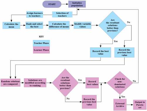
TLBO is an advanced technique which is basically composed of two phases viz. teaching and learning. The multi-objective version of this algorithm known as MOTLBO simultaneously optimizes multiple objectives. Principally it is based on the philosophical rendition of a relationship between an instructor/teacher and student in a learning environment. Three aspects of a learning environment namely subjects, students and results are described as variables, population and fitness values, respectively (Rao, Savsani, & Balic, Citation2012). Since its introduction, numerous researchers have applied TLBO to many optimization problems while comparing it against other algorithms and observing its parameter-less implementation (Rao, Citation2016). On another note criticisms on the performance of TLBO were suggested by Crepsinek, Liu, and Mernik (Citation2012) and later clarified by Waghmare (Citation2013). However, results in literature express superiority in terms of computational resources and time to solution compared to other algorithms. Due to this increased interest, researchers have also modified the TLBO algorithm to enhance performance by formulating hybrid and/or improved versions. In this study, the MOTLBO is applied on a spur gear design problem for two objectives viz. minimum weight and maximum power output. The MOTLBO is the multi-objective capable variant of the standard TLBO algorithm. It may be classified as a posteriori approach to optimization of multiple objectives. Essentially this refers to the generation of a Pareto frontier, from which optimal solutions may be derived based on various decision methods. While maintaining the basic architecture of the TLBO algorithm, the MOTLBO introduces a sorting and computation mechanism viz. non-dominated and crowding distance, respectively. Non-dominated sorting ensures that only the best solutions are selected after every iteration. According to Siegmund, Ng, and Deb (Citation2012), a solution A, dominates another solution B, if, A is numerically preferred to B for objective (s), and restored for at least one objective. The MOTLBO algorithmic process is shown in Figure representing all stages of an iteration.
Figure 1. MOTLBO flow chart
2.1. Teacher phase
Naturally, the instructor/teacher is considered the current best result and all learners are expected to gravitate towards this result as the teaching process progresses. In MOTLBO, the number of teachers is increased and these are selected from the learners and have higher crowding distance values (Lin et al., Citation2015). The mean result is computed as the compounded product of the random value, variable mean, teaching factor and difference in best value. The teaching factor (TF) is randomly generated and is not a set parameter in the TLBO algorithm. Mathematically this phase may be evaluated as shown in EquationEquations (1(1)
(1) –Equation3
(3)
(3) ).
where represents the best learner now designated teachers grade in subject j. The parameter TF is defined as the teaching factor whose value influences the value of the mean to be altered. The random factor, ri can be any value in the range 0 to 1. Teaching factor (TF) influences the mean value with its value randomly elected as either 1 or 2 using EquationEquation 2
(2)
(2) .
The obtained or present solution denoted by k in EquationEquation 3(3)
(3) is now updated in the teacher phase, based on the Difference_Mean j, i, which is calculated in EquationEquation 1
(1)
(1) , by applying EquationEquation 3
(3)
(3) .
In EquationEquation 3(3)
(3) the parameter
is the updated value of
the former parameter/solution is then accepted provided it is superior over the previously obtained solution. These superior solutions are preserved for initial input in the secondary phase which is the learner phase. In terms of the selection operator, if
dominates
, the latter is replaced by the former. However, if the values are similar either value and design variables may be selected.
2.2. Learner phase
It is common knowledge that a learner’s progress will vary amongst individuals with some improving by interacting with their fellow classmates. When a learner who is more advanced in a subject interacts with others, they will improve their peers but will not necessarily degrade themselves. However, this transfer of knowledge will happen if peers have more knowledge. In this phase, learners are randomly paired and evaluated by applying EquationEquations (4(4)
(4) ,Equation5
(5)
(5) ) depending on domination. If Xj is dominated EquationEquation 5
(5)
(5) is applied while Xi is dominated.
At the end of this process, determination of selected individuals (old/new) is achieved for the next iteration. The best solution is then selected using the selection operator shown in EquationEquation 3(3)
(3) .
2.3. Algorithmic specific parameters
In the present study the following parameter settings were applied;
Teaching factor = 1
Number of iterations = 300
Number of teachers = 3
Crowding distance number = 0
3. Decision-making techniques in multi-objective optimization
Unlike single objective, multi-objective optimization results require further investigation to suit designer preferences. Multi-objective optimization without the priori articulation of preferences, results in a Pareto frontier with a multitude of objective solution combinations. It is from this Pareto frontier that tradeoff studies are performed in order to determine a preferred optimum solution. Numerous methods may be applied to study the Pareto frontier of solutions as reported by number of researchers (Arora, Kaushik, Kumar, & Arora, Citation2016a, Citation2016b, Citation2016c; Arora, Kaushik, & Kumar, Citation2017; Kumar, Kaushik, Kumar, & Hans, Citation2016), to determine optimal results. In this research work, two different decision-making techniques have been applied namely, LINMAP and TOPSIS, in order to determine or select the final solutions from the Pareto frontier generated using the MOTLBO algorithm. However, since objectives are scaled and dimensionalized differently, methods of non-dimensionality may be applied as shown by EquationEquations (6(6)
(6) –Equation10
(10)
(10) ).
Non-dimensioned methods
Using the linear method,
Using the Euclidean approach for TOPSIS and LINMAP techniques
Using the Fuzzy approach for Fuzzy Bellman-Zadeh technique
Where Fij, represents the objectives matrix of the Pareto solutions, the symbol i indexes points generated on the frontier while j represents objectives in the search space.
3.1. LINMAP technique
LINMAP is an acronym that means Linear Programming for Multidimensional Analysis of Preference. In this technique, a Euclidean distance, di+, is computed for every obtained solution against the ideal solution. Ideal solution optimizes all objectives or rather defines the optimum value of each objective and resultantly is therefore not on the frontier.
By applying this technique an ideal point may be obtained by evaluating, using EquationEquation 11(11)
(11) , the Euclidean distance as follows:
n, denotes the number of variables investigated, while i indicates the pareto path, i.e., (i = 1, 2, 3 …, m). represents the ideal value of the jth objective obtained. The optimal solution is characterized by the least distance from the ideal point. This obtained value represents the derived result.
3.2. TOPSIS technique
TOPSIS is an acronym that means Technique for Order of Preference by Similarity to Ideal Solution. Unlike the LINMAP method TOPSIS considers the nadir value instead of the ideal value. In this case, the Euclidean distance, di-, is computed using EquationEquation 12(12)
(12) . The calculated values of d determine the optimal values to be selected on the Pareto frontier as follows;
Therefore, in pursuant of the desired optimal solutions distance metrics are applied in this research work using LINMAP and TOPSIS decision methods. The optimum solution is selected as the one which is closest to the ideal, but furthest from the nadir point, using distance metrics. To achieve this, objectives must be dimensionless and this can be achieved through the Euclidean, Linear and fuzzy methods.
4. Optimal weight gear design
In this study, weight and power output objectives are investigated simultaneously. Four design cases based on a single gear stage, initially investigated by Yokota et al. (Citation1998) are considered. As shown in Figure the gear system is composed of two cylindrical gears namely pinion and gear, according to size and driving/driven functionality. Gears are available in numerous structures as reported by Wang, Wang, and Wang (Citation2017). However, in the current study, a gear model with six holes and hubs is considered. Yokota et al. (Citation1998) considered one case which was inaugurated as the first case when investigated by Savsani et al. (Citation2010), while extending the objective formulations to a second case involving six variables and eight constraints. Padmanabhan, Chandrasekaran, Asokan, and Raman (Citation2013) obtained optimal solution for gear drive design using population-based algorithm. Case 1 involved five variables viz. module, face width, pinion and gear shaft diameters and number of teeth on pinion and five constraints based on gear bending strength, centre distance and shaft torsional strength. Furthermore, problem formulation considered in case 2 was influenced by the AGMA design procedure. According to the literature surveyed the optimal weight design problem was applied to various algorithms while considering two case studies differentiated by mathematical formulation of the design problem.
Each case is investigated twice while varying the variable ranges to result in four design cases investigated in this study. In both cases, minimum weight optimization was considered for single objective formulations.
Techniques such as genetic, particle swarm, teaching learning based and grey wolf optimizer algorithms (Dörterler et al., Citation2019; Rao, Citation2016 Savsani et al., Citation2010; Yokota et al., Citation1998) were applied.
With regard to both case 1 and 2 (Yokota et al., Citation1998), and (Savsani et al., Citation2010) applied similar parameter values for population size, mutation probability. Adjusted cross over probability and maximum generation were 0.8 and 300, respectively, for case 2 investigated by Savsani et al. (Citation2010) as compared to 0.4 and 1000 for case 1. Various parameter settings were also applied for PSO and SA as investigated in literature with varying results obtained which suggested an improvement in the solution. Rao (Citation2016) introduced the TLBO algorithm and applied it to the OWD problem investigated in the present work considering both cases. In the present research work the optimal weight design problem is investigated by considering two objectives viz. weight and power. Four design cases with problem specifications shown in Table are investigated. These design cases are detailed in section 6 of this research paper.
Figure 2. Single stage spur gear system (Dörterler et al., Citation2019)
Table 1. Optimal design problem specifications
5. Maximum power output
This refers to the resultant power in kilowatts of a gear transmission system. In comparison, power input is higher than output due to loss in power caused by dynamic, bearing and seal contact factors. However, the number of potential factors is large due to interactions between lubrication and gear meshing (Petry-Johnson, Kahraman, Anderson, & Chase, Citation2008) such that a generalization of these factors has load dependency. Load dependency may be also classified as contact and non-contact losses. In contact loss, the major factor is frictional losses as represented by EquationEquations (13(13)
(13) –15).
Li, Vaidyanathan, Harianto, and Kahraman (Citation2009) refers to the normal load and coefficient of friction at each contact point and angle
respectively.
The sum of contact power loss and efficiency, as represented by EquationEquations (16(16)
(16) ,Equation17
(17)
(17) ), is an average of their instantaneous values shown by EquationEquations (18
(18)
(18) ,19) (Li et al., Citation2009)
In summation, according to Miler et al. (Citation2018) power output may be calculated by applying EquationEquation 20(20)
(20) as follows;
6. Mathematical problem
In the current research work, four design case studies based on the gear model described in section 4 are investigated. In this section, the four case studies which differ on variable and constraint set formulations are described.
Design case 1 (a)
This design case is composed of six design variables and five constraints of non-linear nature are considered. The six design variables viz. face-width, module, pinion tooth number, pinion shaft, gear shaft diameter and power input are considered. On the other hand, the five non-linear constraints viz. gear bending strength, centre distance and shaft torsional strength are adopted as applied by Yokota et al. (Citation1998). The objective functions for case 1(a) are formulated as shown in EquationEquations (21(21)
(21) –Equation24
(24)
(24) ).
Subject to the following constraints, EquationEquations (25(25)
(25) –Equation29
(29)
(29) ).
where constraints to
represent bending strength of tooth, surface durability, torsional strength of shafts for pinion, gear and centre distance, respectively. The design variables were considered according to the ranges defined in EquationEquations (30
(30)
(30) –Equation35
(35)
(35) ).
The various parameters defined in the mathematical problem (Dörterler et al., Citation2019) are expressed by EquationEquations (36(36)
(36) –Equation49
(49)
(49) )
Design case 1(b)
In this design case, a different set of variable ranges was applied to objectives formulations considered in EquationEquations (21(21)
(21) –Equation24
(24)
(24) ) as compared to the ranges shown in case 1(a) in EquationEquations (30
(30)
(30) –Equation35
(35)
(35) ). In case 1(b) the design variables were considered in the ranges shown in EquationEquations (50
(50)
(50) –Equation55
(55)
(55) ).
Design case 2 (a)
In design case 2 (a), eight design variables and eight constraints were considered. Additional to the formulations investigated in cases 1(a) and 1(b), two variables namely hardness, H and contact ratio, were also considered as shown in EquationEquations (56
(56)
(56) –Equation57
(57)
(57) ).
where the objectives, W and Pout are represented by EquationEquations (23(23)
(23) –Equation24
(24)
(24) ). The additional design variables considered in case 2(a) are shown in EquationEquations (58
(58)
(58) –Equation59
(59)
(59) )
Design case 2(a) is investigated subject to eight constraints as expressed by EquationEquations (60(60)
(60) –Equation67
(67)
(67) )
Case 2 parameter formulations are expressed in EquationEquations (68(68)
(68) –Equation71
(71)
(71) ).
Design case 2(b)
The variation of this design case to that of 2(a) is similar in comparison to that expressed between case 1(a) and case 1(b). In this design case 2(b), a different set of variable ranges was applied to objectives formulations considered in EquationEquations (56(56)
(56) –Equation57
(57)
(57) ). In case 2(b) the design variables were similar to those of case 1(b) with additional variables considered as shown in EquationEquations (58
(58)
(58) –Equation59
(59)
(59) ).
7. Results and discussions
In the current research work, multi-objective optimization of a single-stage gear system initially proposed by (Yokota et al., Citation1998), is investigated using the MOTLBO algorithm. Four design case studies based on a single gear stage system have been formulated and investigated as described in section 6 of the current research work. Computational runs of the design problems were done and the results are shown and described in this section. Table shows these results and the calculated deviation index for each method.
Table 2. Optimal results using decision methods for case 1(a)
Figure shows the optimization results for case 1(a) with a Pareto frontier of optimal solutions obtained. LINMAP and TOPSIS decision methods are applied to extract optimal values based on a difference method involving the ideal and nadir points.
Nadir and Ideal solution points for weight and power output are 7324 g, 7.139 kW and 2719 g and 14.93 kW. LINMAP method obtained 4698 g and 12.2 kW while TOPSIS method resulted in 4574 g and 11.95 kW as optimal solution sets. The calculated deviation indexes were 0.67 and 0.43 for LINMAP and TOPSIS, respectively. Therefore, in this case the TOPSIS solution is optimal.
In case 1(b), variable limits were applied and optimization was performed for the same design case. Figure shows the Pareto frontier obtained while Table displays the results. Nadir and Ideal solution points obtained are 7255 g, 7.377 kW and 2358 g and 14.94 kW, respectively. The LINMAP and TOPSIS solution sets were discovered at 4368 g, 12.41 kW and 4527 g and 12.96 kW, respectively. Deviation indices were computed at 0.41 and 0.44 for LINMAP and TOPSIS, respectively. Hence,, in this case, the LINMAP solution is optimal.
Figure 3. Weight and power output optimization case 1(a) using MOTLBO
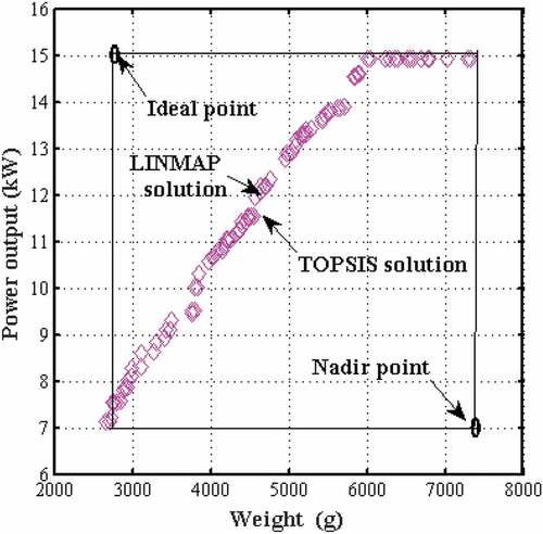
Figure 4. Weight and power output optimization case 1(b) using MOTLBO
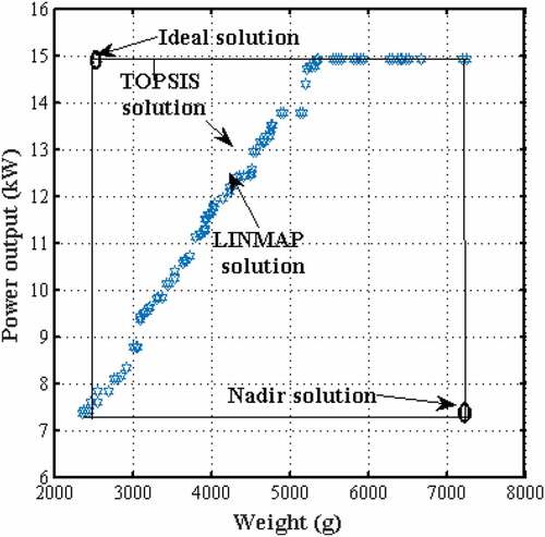
Figure 5. Weight and power output optimization case 2(a) using MOTLBO
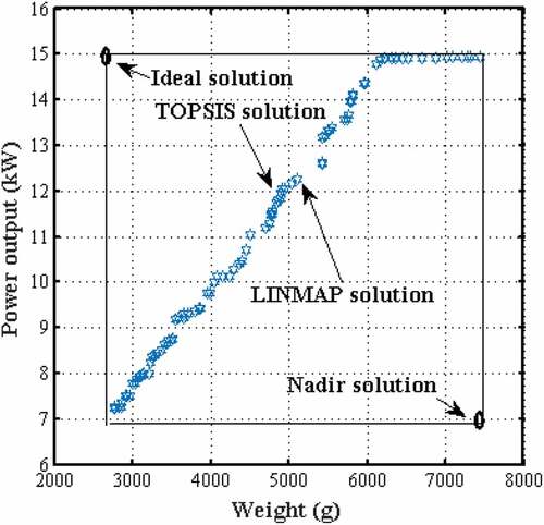
Table 3. Optimal results obtained using decision methods for case 1(b)
Design case 2(a) is defined by eight variables and eight design constraints employed to investigate the multi-objective optimization of weight and power output.
Figure shows the Pareto frontier obtained for this defined design case. As shown in Table , nadir and ideal solutions were obtained as 7441 g, 7.22 kW and 2766 g, 14.93 kW. LINMAP and TOPSIS solution sets were obtained as 5028 g, 12.16 kW and 4891 g, 11.95 kW. Computation for deviation indexes are 0.48 and 0.45 for LINMAP and TOPSIS, respectively.
Figure 6. Weight and power output optimization case 2(b) using MOTLBO
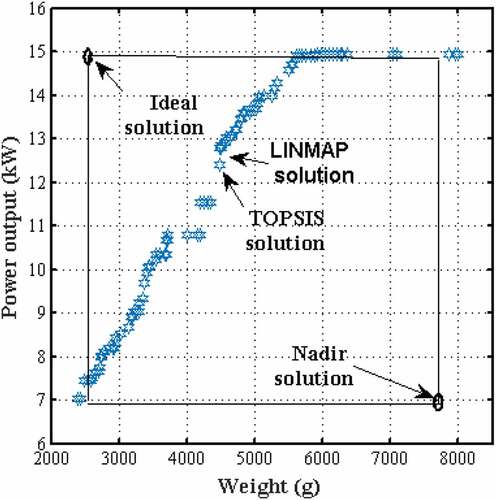
Table 4. Optimal results using decision methods for case 2(a)
Design case 2(b) employs the variable set defined in case 2(a) while applying the variable ranges suggested by (Savsani et al., Citation2010) in the investigation of the original OWD problem. Figure shows the generated Pareto frontier, LINMAP and TOPSIS solution sets obtained.
Nadir and ideal solutions were obtained as 7988 g, 7.016 kW and 2388 g, 14.94 kW, respectively. LINMAP and TOPSIS solutions are 4585 g, 13.04 kW and 4484 g, 12.4 kW, respectively. Computations of deviation resulted in 0.39 and 0.37 indexes for LINMAP and TOPSIS as shown in Table . In all the four design cases considered a deviation index was applied to determine the best optimal value from the generated Pareto frontier. Table shows the optimal results obtained for each design case which was investigated. Case 1(b) had superior weight values as compared to the three other design cases. These optimal results were validated against those previously obtained in literature while investigating the OWD problem using GA, SA, PSO, TLBO, ETLBO and GWO. In this research work, the OWD problem is extended to include power output maximization and the trade-off optimal solution is sought for the present design problem.
Table 5. Optimal results using decision methods for case 2(b)
Table 6. Optimal results for design cases investigated in the present work
Validation of the study
Considering the four design cases investigated, Table shows that case 1(b) resulted in a superior solution compared to case 1(a), case 2(a), case 2(b). The results shown in Figures – show that weight increase will result in power output increasing for a defined range. As shown in Figures and , for case 1(a) and case 2(a), the defined range terminates at 6000 g and no improvement is registered for any increase in weight thereafter. However, for case 1(b) and case 2(b) as shown in Figures and , the defined range terminates earlier at approximately 5500 g. This difference may be attributed to the different variable sets and ranges employed for each design case. The obtained results were validated on a case by case basis. As shown in Table , with regard to case 1 (a) and with respect to GA, SA, PSO, TLBO, ETLBO, GWO, the optimal result was 30.2%, 46.2%, 46.2%, 50.6%, 50.9% and 253% higher than values obtained by previous authors (Yokota et al., Citation1998; Savsani et al., Citation2010; Rao, Citation2016, Dörterler et al., Citation2019) . Similarly, for case 1(b), Table shows variance values as 24%, 41%, 41%, 45%, 46% and 237%. Table shows results validation for case 2 (a) with optimal value variances as 39%, 63%, 63%, 63%, 93%, 96% and 65%. The fourth design case, case 2 (b), obtained variances of 27%, 69%, 69.94%, 69.94%, 71.87%, 72.17% and 246%. Previous authors investigated single objective mathematical formulations as compared to the current study that considered multi-objective formulations. Although all weight values were significantly higher, in the current study case 1 (b) was optimal with 4368 g and 12.41 kW. In the current study, optimal values obtained via trade-off between a range of weight and power output values were not informed by any design preference but by a search for the best non-dominated solutions. Therefore, considering the minimum possible weight values for the four design cases in chronological order, the following optimal results were obtained 2719 g, 7.139 kW, 2358 g, 7.377 kW, 2766 g, 7.22 kW, 2388 g, 7.016 kW. All minimum weight values obtained show improvement in almost all the cases except for GWO results in all design cases, SA, PSO, TLBO, ETLBO results for case 2(b) and TLBO, ETLBO results for case 2(a).
Table 7. Validation results for case 1(a)
Table 8. Validation results for case 1(b)
Table 9. Validation results for case 2(a)
Face-width is a gear geometric parameter that defines the lengthwise measurement of the gear along its axis. As such for a gear of particular size, the weight or volume may be further varied by increasing or reducing the face-width. Validation results for case1(a) reflect that the face-width value was higher than that obtained using GA, SA, PSO and GWO but lower than the values obtained for TLBO and ETLBO regardless of a significantly higher optimal weight value. The pinion tooth number value was close to the minimum possible and also lower than TLBO and ETLBO values. The module value was higher than those recorded by previous authors. The shaft diameter values were lower in most cases although higher shaft diameters are required to reduce overall weight of gear. Unlike results obtained for case 1(a), face-width value for case1(b) was higher as compared to all previous literature. Lower shaft diameters were also obtained in all cases. The pinion tooth number values were higher than those obtained using GA and GWO but lower than all other records. The module value was higher than all records except for TLBO and ETLBO investigations.
Case 2(a) considers the same design problem with different variables, compared to those described by (Dörterler et al., Citation2019) as expanded variables. Hardness number which may define type of material applied is also added as a variable. In the current study, the variable set is further extended to include input power and a contact ratio factor. Tables and 1 show the results obtained by investigating two objectives viz weight and power output using MOTLBO algorithm.
Table 10. Validation results for case 2(b)
Validation results for case 2(a) in Table show that face-width was higher than that obtained in previous literature and shaft diameters were the lowest in all cases. The pinion tooth number was similar in all records compared but module difference was higher as compared to that observed in all cases. The hardness number was the lowest compared to previous literature indicating the selection of an inferior material. In order to transmit a required power output, the contact ratio would increase proportionally with the face-width. This results in the increase of gear system weight. Case 2(b) results are in analysis, similar to those obtained in case 2(a) except for gear hardness number that was constant through all design stages.
The results obtained using MOTLBO algorithm yield higher weight values as compared to those obtained by previous authors. This could be attributed to the multi-objective consideration of the current study which focuses on trade-off between objectives. According to the literature surveyed on the OWD problem, several authors have considered weight only as an objective function hence, the power output values are not available in these studies (Dörterler et al., Citation2019; Rao, Citation2016; Savsani et al., Citation2010; Yokota et al., Citation1998). In the current study, the authors have carried out multi-objective optimization in view of maximizing power and minimizing weight. Thus, the optimized values of weight are more than that of values obtained in the previous literature as multi-objective algorithm simultaneously optimizes two objectives which may lead to the improvement of any one objective at the cost of other. However, ideal solution results obtained in the present study reflect minimum weight values which are superior to those obtained in previous literature.
The optimal weight design problem has not been investigated with regard to the power output objective, according to the literature surveyed. Therefore, in this research work, power output results were validated against results obtained in a study by (Padmanabhan, Srinivasa Raman, & Chandrasekaran, Citation2014). Four objectives viz. power output, efficiency maximization, centre distance and weight minimization were investigated using the Selective Breeding Algorithm (SBA).
Although (Padmanabhan et al., Citation2014) reported volume instead of weight, the authors applied 7900kg/m3 as density of the applied material. Table shows the results obtained in the current study against those reported by (Padmanabhan et al., Citation2014). The power output values obtained in this research were superior compared to those obtained by previous authors for similar number of teeth. The increased volume in the results obtained by (Padmanabhan et al., Citation2014) may be attributed to higher face-width and module values as shown in Table .
Table 11. Power output validation
Contrary to the current research work, a Pareto set of solutions is not reported by (Padmanabhan et al., Citation2014) but rather optimum values obtained using different methods are shown. Therefore the results shown by (Padmanabhan et al., Citation2014) reflect an improvement in solution against different methods applied. In the current research work, the Pareto curves shown in Figures – show that an increase in weight also results in an increase in power output for a specific range of values. This result is also validated by research results shown by (Patil, Ramkumar, & Krishnapallai, Citation2017) whereby an increase in volume is related to a decrease in a power loss factor. In other research work also power loss is reported to decrease as volume increases (Miler et al., Citation2018). Since reduction in power loss results in increased power output, it therefore can be concluded volume/weight increase will result in power output increase for a defined range of values. Furthermore, multi-objective optimization results in a trade-off of objectives whereby extreme minima and maxima is not achieved but rather a compromise solution. Hence in this study, the resultant effect of considering power output and volume simultaneously on the optimal solution is also demonstrated.
8. Conclusions
In the present study, a multi-objective spur gear design problem considering weight and power was investigated using MOTLBO. The design problem is an extension of an optimum weight design problem previously investigated in literature using various optimization techniques.
Four design cases including different number of variables viz. module, face width, pinion and gear shaft diameters and number of teeth on pinion power input and contact ratio, were formulated with different variable ranges, investigated. Pareto frontiers were generated and investigated using decision-making techniques LINMAP and TOPSIS to obtain the best optimal solutions.
Resultantly, optimal weight values were found to be higher when the weight and power output objectives were considered simultaneously. An analysis of minimum possible values obtained on the Pareto frontier reflected that improved results were obtained as compared to those obtained using the GA, SA, PSO algorithms. The module variable showed significant impact with all lower weight solutions computed with the lowest attained module size. The inclusion of hardness number and contact ratio variables also reflected how the decreasing change in hardness requires an increasing change in face-width and contact ratio thereby leading to increased gear weight. Generally, an increase in shaft diameter would induce a decrease in gear weight when considering the gears instead of the complete system.
MOTLBO algorithm for simultaneous optimization of weight and power output on this design problem has been explored for the first time in this study. Results obtained have reflected that solutions are optimal depending on design context and articulation of preferences. The input power objective has been varied over a defined range and each Pareto frontier reflects that an increase in weight will result in an increase in power output. The technique applied has shown ability to obtain improved results as compared to previous authors when minimum possible values are considered. In future research, the authors propose application of other multi-objective techniques and decision methods.
Nomenclature
| ri | = | Random number |
| Tf | = | Teaching factor |
| v | = | Pitch line velocity (m/s) |
| τ, | = | Shaft shear, (MPa). |
| σ | = | gear material strength (MPa) |
| Pout | = | Power Output (kW) |
| Pin | = | Input Power (kW) |
| Ploss | = | Power loss (kW) |
| Tin | = | Input torque (Nm) |
| N1 | = | Input rpm |
| bw | = | Web thickness (mm) |
| d2 | = | Gear shaft diameter (mm) |
| Di | = | Rim diameter (mm) |
| Dr | = | Dedendum diameter (mm) |
| D2 | = | Gear diameter (mm) |
| D1 | = | pinion diameter (mm) |
| d1 | = | Pinion Shaft diameter (mm) |
| dp | = | Diameter of hole (mm) |
| W | = | Weight, g (grams) |
| H | = | Hardness (BHN) |
| Sn | = | Endurance limit |
| Sfe | = | Surface fatigue strength (MPa), |
| m | = | module |
| Cr | = | contact stress factor |
| Ci | = | hardness ratio factor |
| g2 (x) | = | Surface strength constraint |
| g4(x), g5(x) | = | Uniform load distribution constraints |
| g8(x) | = | Centre distance. |
| Kv | = | Velocity (m/s) |
| Kms | = | Mean stress |
| ∅ | = | Pressure angle ° |
| y | = | Tooth form factor |
| ρ | = | density (mg/m3) |
| l | = | boss length (mm) |
| Fp | = | wear load (N) |
| Fs | = | bending load (N) |
| Cp | = | Elasticity coefficient |
| ω | = | Angular velocity (rad/s) |
| b | = | Face width (mm) |
| μm | = | Friction coefficient |
| = | gear ratio | |
| N2 | = | Output rpm |
| lw | = | Rim thickness (mm) |
| do | = | Boss diameter (outside) (mm) |
| Z1 | = | Number of teeth on pinion |
| εα | = | Transverse contact ratio |
| ε1 | = | Tip contact ratio of pinion |
| ε2 | = | Tip contact ratio of pinion |
| η | = | efficiency |
| n | = | Number of holes |
| J | = | Lewis Geometry factor. |
| Cs | = | Surface factor. |
| r | = | Gear radii (mm) |
| Kw | = | Load factor |
| KB | = | rim thickness |
| J | = | geometry factor of bending stress |
| g1 (x) | = | Bending strength constraint |
| g3(x) | = | Obtrusion check |
| g6(x), g7(x) | = | Shaft torsion constraints |
| Kr | = | Bending reliability |
| Km | = | load distribution factor |
| Ko | = | Over load factor |
| Ks | = | Size factor |
Additional information
Funding
Notes on contributors
Edmund S. Maputi
Edmund S. Maputi is a Lecturer with the Department of Industrial and Manufacturing Engineering, Harare Institute of Technology, Harare, Zimbabwe. He is also a PhD Scholar at Amity University Haryana, India. He received his MTech in Engineering Design from the Jawaharlal Nehru Technological University Hyderabad, India in 2014 . His research interests include engineering design, optimization, drivetrain systems and Soft computing in engineering design.
Rajesh Arora
Rajesh Arora is working as an Associate Professor in the Mechanical Engineering Department, Amity University Haryana, Gurgaon. He received his Doctorate from the YMCA University of Science & Technology, Faridabad and Masters from Indian Institute of Technology, Delhi. His areas of expertise are energy and exergy analysis of thermal power plants, heat transfer, solar photovoltaics, computational fluid dynamics, gear designing, multi-objective optimisation and decision making. He has made significant contributions in these fields as evident by his above 30 research publications in journals of repute at national and international levels.
Related Research Data
References
- Arora, R., Kaushik, S. C., & Kumar, R. (2017). Multi-objective thermodynamic optimisation of solar parabolic dish Stirling heat engine using NSGA-II and decision making. International Journal of Renewable Energy Technology, 8(1), 64–25. doi:10.1504/IJRET.2017.080873
- Arora, R., Kaushik, S. C., Kumar, R., & Arora, R. (2016a). ‘Soft computing based multi-objective optimization of Brayton cycle power plant with isothermal heat addition using evolutionary algorithm and decision making’. Applied Soft Computing, 46, 267–283. doi:10.1016/j.asoc.2016.05.001
- Arora, R, Kaushik, S.C, & Kumar, R. (2016b). Multi-objective thermodynamic optimization of solar parabolic dish stirling heat engine with regenerative losses using nsga-ii and decision-making. Applied Solar Energy, 52(4), 295-304.
- Arora, R., Kaushik, S. C., Kumar, R., & Arora, R. (2016c). Multi-objective thermo- economic optimization of solar parabolic dish Stirling heat engine with regenerative losses using NSGA-II and decision making. International Journal of Electrical Power & Energy Systems, 74, 25–35.
- Crepsinek, M., Liu, S., & Mernik, L. (2012). A note on teaching – Learning-based optimization algorithm. Information Sciences, 212, 79–93. doi:10.1016/j.ins.2012.05.009
- Deb, K., & Jain, S. (2003). Multi-speed gearbox design using multi-objective evolutionary algorithms. Journal of Mechanical Design, 125(3), 609–619. doi:10.1115/1.1596242
- Dörterler, M., Şahin, İ., & Gökçe, H. (2019). A grey wolf optimizer approach for optimal weight design problem of the spur gear. Engineering Optimization, 51(6), 1013–1027. doi:10.1080/0305215X.2018.1509963
- Hofstetter, M., Lechleitner, D., Hirz, M., Gintzel, M., & Schmidhofer, A. (2018). Multi-objective gearbox design optimization for x{EV}-Axle drives under consideration of package restrictions. Dritev - Drivetrain for Vehicles. doi:10.1007/s10010-018-0278-9
- Kumar, R., Kaushik, S. C., Kumar, R., & Hans, R. (2016). Multi-objective thermodynamic optimization of an irreversible regenerative Brayton cycle using evolutionary algorithm and decision making. Ain Shams Engineering Journal, 7(2), 741–753. doi:10.1016/j.asej.2015.06.007
- Li, S., Vaidyanathan, A., Harianto, J., & KAHRAMAN, A. (2009). Influence of design parameters on mechanical power losses of helical gear pairs. Journal of Advanced Mechanical Design, Systems, and Manufacturing, 3(2), 146–158. doi:10.1299/jamdsm.3.146
- Lin, W., Yu, D. Y., Wang, S., Zhang, C., Zhang, S., Tian, H., … Liu, S. (2015). Multi-objective teaching – Learning-based optimization algorithm for reducing carbon emissions and operation time in turning operations. Engineering Optimization, 47(7), 994–1007. doi:10.1080/0305215X.2014.928818
- Maputi, E. S., & Arora, R. (2019). Design optimization of a three-stage transmission using advanced optimization techniques. International Journal of Simulation and Multidisciplinary Optimization, 10, A8. doi:10.1051/smdo/2019009
- Messac, A. (1996). Physical programming - Effective optimization for computational design. American Institute of Aeronautics and Astronautics Journal, 34(1), 149–158. doi:10.2514/3.13035
- Messac, A. (2015). Optimization in practice with MATLAB®: For engineering students and professionals. Cambridge: University Press. Cambridge University Press.
- Miler, D., Žeželj, D., Lončar, A., & Vučković, K. (2018). Multi-objective spur gear pair optimization focused on volume and efficiency. Mechanism and Machine Theory, 125, 185–195. doi:10.1016/j.mechmachtheory.2018.03.012
- Mogal, Y.K., & Wakchaure, V.D. (2013). A multi-objective optimization approach for design of worm and worm wheel based on genetic algorithm. Bonfring International Journal Of Man Machine Interface, 3(1), 8-12. doi: 10.9756/BIJMMI.14403
- Padmanabhan, S., Chandrasekaran, M., Asokan, P., & Raman, V. S. (2013). Optimal solution for gear drive design using population based algorithm. Young, 852, 852–864.
- Padmanabhan, S., Srinivasa Raman, V., & Chandrasekaran, M. (2014). Optimisation of gear reducer using evolutionary algorithm. Materials Research Innovations, 18, S6–378–83. doi:10.1179/1432891714Z.000000000983
- Patil, M., Ramkumar, P., & Krishnapallai, S. (2017). Multi-objective optimization of two stage spur gearbox using NSGA-II, “SAE Technical Paper 2017-28-1939. doi: 10.4271/2017-28-1939
- Petry-Johnson, T. T., Kahraman, A., Anderson, N. E., & Chase, D. R. (2008). An experimental investigation of spur gear efficiency. Journal of Mechanical Design, 130(6), 062601. doi:10.1115/1.2898876
- Rai, P., Agrawal, A., Saini, M.L., Jodder, C. and Barman, A.G. (2018). Volume optimization of helical gear with profile shift using real coded genetic algorithm. Procedia Computer Science, Elsevier B.V. 133, 718–724. doi:10.1016/j.procs.2018.07.127
- Rao, R. V. (2016). Teaching learning based optimization algorithm. doi:10.1007/978-3-319-22732-0
- Rao, R. V., Savsani, V. J., & Balic, J. (2012). Teaching – Learning-based optimization algorithm for unconstrained and constrained real-parameter optimization problems. Engineering Optimization, 44(12), 1447–1462. doi:10.1080/0305215X.2011.652103
- Sanghvi, R. C., et al. (2014). Multi-objective optimization of two-stage helical gear train using NSGA-II. Journal of Optimization, 2014, 8. doi:10.1155/2014/670297
- Savsani, V., Rao, R. V., & Vakharia, D. P. (2010). ‘Optimal weight design of a gear train using particle swarm optimization and simulated annealing algorithms’. Mechanism and Machine Theory, 45(3), Elsevier Ltd, 531–541. doi:10.1016/j.mechmachtheory.2009.10.010
- Siegmund, F., Ng, A. H. C., & Deb, K. (2012). ‘Finding a preferred diverse set of Pareto-optimal solutions for a limited number of function calls’, 2012. IEEE Congress on Evolutionary Computation, CEC. doi:10.1109/CEC.2012.6256654
- Thompson, D. F., Gupta, S., & Shukla, A. (2000). Tradeoff analysis in minimum volume design of multi-stage spur gear reduction units. Mechanism and Machine Theory, 35(5), 609–627. doi:10.1016/S0094-114X(99)00036-1
- Waghmare, G. (2013). Comments on “a note on teaching-learning-based optimization algorithm”. Information Sciences, 229(December), 159–169. doi:10.1016/j.ins.2012.11.009
- Wang, C., Wang, S., & Wang, G. (2017). Volume models for different structures of spur gear. Australian Journal of Mechanical Engineering, Taylor & Francis, (October), 1–9. doi: 10.1080/14484846.2017.1381373
- Yokota, T., Taguchi, T., & Gen, M. (1998). A solution method for optimal weight design problem of the gear using genetic algorithms. Computers & Industrial Engineering, 35(3–4), 523–526. doi:10.1016/S0360-8352(98)00149-1
- Zolfaghari, A., Goharimanesh, M., & Akbari, A. A. (2017). Optimum design of straight bevel gears pair using evolutionary algorithms. Journal of the Brazilian Society of Mechanical Sciences and Engineering, 39(6), Springer Berlin Heidelberg, 2121–2129. doi:10.1007/s40430-017-0733-9