
 ?Mathematical formulae have been encoded as MathML and are displayed in this HTML version using MathJax in order to improve their display. Uncheck the box to turn MathJax off. This feature requires Javascript. Click on a formula to zoom.
Abstract
The geothermal power plant is converting steam to electricity. The evaporation process in the evaporator produces wet steam (brine). The Brine has a high temperature and contains water, which is quite dominating. Therefore, a separator is needed to separate between ammonia-rich vapor that will flow into the turbine and ammonia-poor liquid, which will flow to the regenerator. In this case, the optimal separation uses a vertical separator. The design of vertical separator produces the specifications for brine mass flow rates 55.275 kg/s at circumferential stress 614.93 bar and brine mass flow rates 1.124 kg/s at longitudinal stresses of 1229.87 bar. The analysis result of brine mass flow rate on the lowest circumferential stress was 16.583 kg/s at 573.71 bar, and the highest was 181.372 kg/s at 628.94 bar, while the brine mass flow rate on the lowest longitudinal stress was 1.048 kg/s at 1,147.42 bar and the highest is 1.149 kg/s at 1,257.88 bar.
Keywords:
PUBLIC INTEREST STATEMENT
The main objective of this paper is to design a separator. Although many researchers designed on the separators, very few researchers reported about separators design for the Kalina cycle. The function of the separator is to separate ammonia-rich vapor flowing into the turbine and ammonia-poor liquid flowing into the regenerator. In this case, the optimal separation uses a vertical separator.
Many researchers compared the types in their work. Although there is similar work, in this work, the effect of brine on the circumferential and longitudinal stresses are studied exclusively.
From this study, we conclude that there is an effect of the brine mass flow circumferential and longitudinal stresses. The increase in brine mass flow on stress values should not exceed the specified value of the provisions of 1,378.952 bar so that it will not cause the risk of explosion on the separator body.
1. Introduction
The Kalina generator or Kalina Cycle System 11 (KCS 11) utilizes the waste heat output from the power plant, especially the geothermal power plant. The Kalina cycle uses a working fluid in the form of a mixture of ammonia and water which can produce an efficiency increase of up to 40% compared to Organic Rankine Cycle (ORC) when using ammonia and up to 20% when using R134a (Elsayed et al., Citation2013)
In general, the KCS11 has a better overall performance at moderate pressures than at the Rankine cycle. The KCS type is suitable for significant energy sources that have a geothermal temperature range of 121°C—204° C (Madhawa, Hettiarachchi, William, William, & Yasuyuki, Citation2007). The main components of the KCS cycle are the evaporator, separator, ammonia turbine, regenerator, mixer, condenser, and pump. Separator in the Kalina cycle has an essential function to separate between the ammonia-rich saturated steam and the ammonia-poor liquid (Modi & Haglind, Citation2015). The steam that enters the turbine is the ammonia-rich steam. Meanwhile, the ammonia-poor steam will inhibit turbine work because it can cause vibration and cause corrosive in turbine blades.
The main techniques used in the industry for the separation of azeotropic mixtures are azeotropic distillation and extractive distillation (Figueirêdo, Brito, Ramos, Vasconcelos, & Brito, Citation2015). The separation of the minimum boiling azeotropes Di-Iso Propil Eter A (DIPE A) at 68.5°C; Isopropyl Alcohol B (IPA B) at 82.1°C; x-azeo, A = 0.78 at 66.9°C with heavy entrainer 2-methoxy ethanol E at 124.5°C, belongs to the 1.0-1a-m1 extractive separation class (Gerbaud & Rodriguez-Donis, Citation2014).
2. Ammonia-water mixture
Ammonia-water mixture has physical and chemical properties that are not the same as pure fluids. Mixing water and ammonia produces a liquid with new physical and chemical properties, where it is necessary to consider the concentration of the mixture. Ammonia boiled at low temperatures (−33,40°C) because it has a lower boiling point and dew point than water.
A non-calibration heat and mass transfer model for the steady-state operation is a column distillation, which is used in the ammonia-water separation or absorption of refrigeration systems to humidify the ammonia vapor produced by the generator (Figueiredo, Fernandes, & Silverio, Citation2006).
3. Separation design method
One of the phase separation methods is the gravity method, which consists of settling and raising. Precipitation is the process of dropping liquid particles in the vapor phase in the separator or the process of settling phases that are heavier in the light phase. In this journal, the standard approach is used by analyzing the effect of brine mass flow on circumferential and longitudinal stress, where the two variables are analyzed, and the construction of a separator is a vertical separator.
The design of vertical separators must take several steps. The first step is to determine the condition of the output of the evaporator. The second stage is choosing the type of mist eliminator so that it can know the value of K or steam capacity that can be handled by the separator and know the vane design factor to find out the value of the drop pressure. The two steps after being done and determined, the next step determines the dimensions of the vertical separator (Moss, Citation2013; Svrcek & Monnery, Citation1993).
The vertical separator needs to set the initial parameters, namely the diameter and the voltage that follows the applicable terms and conditions. The conditions are that the H/D value must not exceed the range 1.5–6 (Svrcek & Monnery, Citation1993), and the stress value must not exceed 1,378.952 bars (Xiuli & Economides, Citation2009).
3.1. The initial parameters of vertical separator calculation
(a) Terminal speed
where is the separator correction factor (m/s);
is liquid density (kg/m3) and
is vapor density (kg/m3).
(b) Vapor speed
(c) Vapor volume flow rate
where is the steam mass flow rate (kg/s).
(d) Fluid flow rate
where is liquid volumetric flow rate (m3/s);
is fluid mass flow rate (kg/s) and
is Liquid/ammonia-water density (kg/m3).
(e) Hold-up and surge volume
where is hold up the volume (m3);
it is surge volume (m3);
is hold up time and
is surge time
3.2. The dimensions of vertical separator calculation (Figueiredo, Fernandes, & Silverio, Citation2006)
(a) Vertical Dimensions of Separators
(b) The height calculation from Low Liquid Level to Normal (NLL)
(c) The height calculation from NLL to High Liquid Level (HLL)
(d) The height calculation from the HLL to the midpoint of the entry of the nozzle
(e) The height calculation of the disengagement from the midpoint of the Nozzle inflow to the Mist Eliminator
(f) Determining the height of Low liquid Level (HLLL)
Knowing the height of the low liquid level, the minimum height for mist eliminator is usually 0.1524 m. Meanwhile, the height from the mist eliminator to the separator head is 0.0254 m. (Moss, Citation2013; Svrcek & Monnery, Citation1993).
(g) The total height of vertical separator
3.3. Head dimension
The calculation of the dimensions of the separator cover includes the parameters (Figure ), which can be calculated using the following equations:
(a) Angle α
where D is vertical separator diameter.
(b) Angle ß
Figure 1. Head separator dimension (Moss, Citation2013)
(c) Height b
(d) Height c
(e) Height e
(f) Height A
(g) Height d
3.4. Determining the diameter of the nozzle
(a) Mixed volume flow rates
(b) Value of ρm
where Q is a mixed volume flow rate (m3/s) and it is mixed phase density (kg/m3).
(c) Diameter of the nozzle entry
(d) Composition Calculation
(e) Diameter to exit steam
where is a vapor volume flow rate (m3/s), and
is vapor density (kg/m3).
(f) Calculates the diameter to get out the liquid
Where is a fluid volume flow rate (m3/s), and
is liquid density (kg/m3).
3.5. Reinforcement pad
The reinforcement pad is an additional material that serves to distribute stress around the hole in the shell separator wall. The way to determine the extent of the reinforcement pad uses a strength reduction factor, namely:
(a) Nozzle and shell strength reduction factor
(b) The factor of reducing the strength of a nozzle and reinforcement with the lowest value
(c) The factor of reinforcement and shell strength reduction
Where Sv is the maximum stress permitted by shell material, and Sp is the maximum stress permitted by the material nozzle.
3.6. Determining area
(a) Extent of reinforcement
(b) Area in shell
(c) The area on the outside of the nozzle with the smallest value
(d) The available area of the nozzle entering the separator by selecting the smallest
(e) Area of welding available on the nozzle that enters the separator with the outer shell
(f) The welding area available on the nozzle with the shell on the inside of the separator
(g) Total reinforcement area
Requirements needed are if the value of the total available area is more than the area needed, then additional reinforcement needs to be needed, and if the opposite is needed, then there is an additional reinforcement pad.
3.7. Determining thickness
(a) Shell thickness
(b) Head thickness
(c) Nozzle thickness
where it is minimum nozzle thickness (m); P is design pressure (bar); D is the diameter of vertical separator (m); S is the maximum stress allowed by material (bar), and E is welding connection efficiency.
3.8. Determine the weight of the separator
Before calculating the separator weight, it is necessary to calculate the area of the shell and head, so that it can calculate the value of the skirt support:
(a) Shell area
(b) Head area
(c) Separator Weight
3.9. Skirt support
The position of the separator is maintained on its balance and strength so that a buffer is needed to hold the separator load. Skirt support type is the most suitable for vertical separators, where the skirt thickness affects the load during hydrostatic testing. The load acting on the skirt is the total vessel load and moment, as for the equation:
where M is a moment on skirt connection (kg/m); W is mass of separator total (kg); R is skirt diameter (m); D is separator diameter (m), and S is maximum skirt material stress (m).
3.10. Determining a pressure drop
The separation process that occurs in the separator causes a decrease in pressure. Calculation of pressure drop needs initial parameters (Table ), using the equation below
Where C is the vane design factor, and K is K-factor (m/s).
3.11. Determining stress on separator
The stress that arises because of pressure on the material is divided into three:
(a) Circumferential Joint Stress
Circumferential stress has a direction that is parallel or perpendicular to the cylinder axis. The equation for calculating stress is:
where P is the fluid pressure in the pipe (bar); D is the diameter of the pipe (m); t is the pipe wall thickness (m).
(b) Longitudinal Joint Stress
Longitudinal stress is a stress that is in the same direction or longitudinal with the cylinder axis. Stress calculation using the equation:
(c) Radial Stress
This stress occurs radially. The radial stress value is calculated using the equation:
where is the internal radius of separator (m) and
’ is outlet shell radius (m).
4. Result and analysis
4.1. Specifications analysis
The designed separator meets the specified requirements. The requirement for designing a separator is that the ratio of the height and diameter of the separator (H/D) must not exceed the range of 1.5–6. The value of the H/D ratio obtained is 5.87, which indicates that the vertical separator designed meets the standard of design requirements.
The separator stress that occurs due to pressure evenly distributed on the wall causes stress to the direction of longitudinal , tangential/circumferential (
), and radial (
). The longitudinal stress value and circumferential stress value are not allowed to exceed 1,378.952 bars. The
and
values obtained from the design calculations are 1,296.879 bar and 648.439 bar.
The results shown in Table have met the standards because of not exceeding the value of 1,378.952 bar. The radial stress (Sr) value is the ratio between the separator internal radius and separator material thickness (). If the value is greater than 10, it can override the radial stress value. The diameter of the separator (shell) obtained from the design is 1.091 m, as shown in Table , or the radius value is 0.546 m, while the thickness is 1.58 cm or 0.0158 m. So that the stress value is 32.6, which can be neglected.
Table 1. Initial parameters
Table 2. Dimension of vertical separator design
4.2. Analysis of separation separator process
Density is one of the properties of a fluid. A fluid cannot ignore the effects of temperature and density because the liquid expands and hardens when the temperature changes. Changes in fluid density depend on temperature and pressure, changes in density can be a lot or a little, if the density is only slightly affected by changes in temperature and pressure, the fluid is called incompressible (Moss, Citation2013), while fluid which is sensitive toward that variable changes is compressible. The working fluid in this separator is incompressible because of the influence of temperature and minimal pressure on changes in density Mc. Cabe, W., Smith, J., & Harriott, Citation2004).
The property commonly used to determine fluid compression is the bulk modulus. If the Modulus Bulk value is not significant, this indicates that the fluid is relatively incapable or tends not to be stressed. It is not able to compress means that it requires significant pressure changes to produce small volume changes, for example, water.
The density difference in the vertical separator is related to the gravitational separation process for vapor phase separation and droplet diameter for liquid phase separation. One of the requirements for separator design explains if the gravity force value is more significant than force drag, then the separation process in the separator can work well (Figueiredo et al., Citation2006). The result of the design calculation of the value of gravity force or terminal velocity (Vt) is 0.738 m/s, and the force drag or vapor speed (Vv) is 0.554 m/s (formula one dan 2). These results indicate that the gravity force value is more significant than force drag (0.738 m/s > 0.554 m/s), this means that the vertical separator is operating optimally, because if it does not meet, the liquid carryover will be occurred on the separator body, so that the vapor can not escape from the liquid. The pressure drop obtained in the design of this separator is 0.0005 bar below the value of pressure drop from other researchers, which are 0.0045 bar (Yohana, Tauviqirrahman, Putra, Diana, & Choi, Citation2018) and 0,00207 bar (Yang, Wang, Wen, & Pham, Citation2017).
4.3. Analysis of brine mass flow variation on circumferential and longitudinal stress
The variation in brine mass flow influenced by stress and needs to be analyzed to find out whether the separator operates safely or not. This analysis avoids the occurrence of accidents and is regulated stress to withstand the explosive effect of the internal pressure of the separator.
The addition of mass flow brine from the design has an impact on the addition of cross-sectional area and separator diameter, because the more extensive the cross-sectional area and the greater the separator diameter, the higher the stress value along with the variation of brine mass flow, as shown in Figures and . The increase in brine mass flow on stress values does not exceed the value of the provisions of 1,378.952 bars so that it will not cause the risk of an explosion on the separator body.
Figure 2. Relationship of brine mass flow to circumferential stress
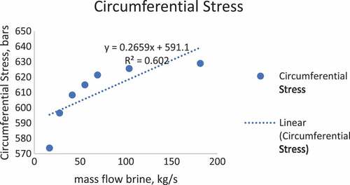
The line graph above illustrates that the greater the brine flow rate, the higher the circumferential stress. This stress is because the increase of the value of the brine flow rate is linear, with the fluid pressure on the separator with other variables (separator diameter and thickness) remain. The stress in the separator is causing stress where this pressure comes from the fluid, and the value is always positive. The stress of fluid works towards tangential, and the amount varies with the wall thickness of the separator, the value of stress given to the separator wall, or the stress value experienced by the separator wall is the same as the pressure given by the fluid. The maximum stress at a vessel obtained is 625 bars; this result is still below the pressure vessel 870 bars (Aseer Brabin, Christopher, & Nageswara Rao, Citation2010).
Figure 3. Relationship of brine mass flow to longitudinal stress
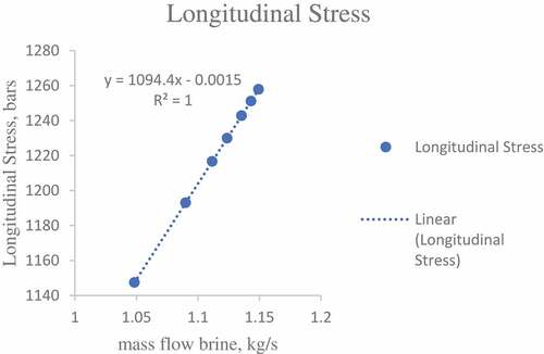
Figure shows that the greater the brine flow rate, the higher the longitudinal stress. This stress is due to the linear relation between the brine flow rate and the fluid pressure in the separator with other variables (separator diameter and thickness) remain. In other words, it shows that the fluid flowing through the separator will practically put stress on the wall of the separator, both in the direction of the length of the separator and evenly on the wall of the separator. It will provide internal stress on the separator (longitudinal stress)(Hadj Meliani, M., Azari, Z., Pluvinage, G., & Capelle, J. Citation2010). The maximum stress obtained is 1260 bar; this result is still below the pressure vessel bar 2114 bars design (Pravin & Damle, Citation2016).
5. Conclusions
There is the influence of the brine mass flow rate on circumferential stress and longitudinal stress, from the results of the design, the circumferential stress value is 614.94 bars, and the longitudinal stress is 1,229.88 bar. The pressure drop obtained in the design of the vertical separator is 0.00053 bar, and this meets the specified pressure drop requirements in the range 0.0002 to 0.0008 bar. The analysis of the effect of the brine mass flow rate on the lowest circumferential stress was 16.583 kg/s at 573.71 bar, and the highest was 181.372 kg/s at 628.94 bar, while the influence of the brine mass flow on the lowest longitudinal stress was 1.048 kg/s at 1,147.42 bar and the highest is 1.149 kg/s at 1,257.88 bar
Additional information
Funding
Notes on contributors
Sri Wuryanti
Sri Wuryanti was born in Indonesia on March 26th, 1965. She received the Ir. degree in Chemical Engineering from Institut Teknologi Sepuluh November (ITS), Surabaya, Indonesia in 1990, and M.Sc. degree in Chemical Engineering from Institut Teknologi Bandung (ITB), Bandung, Indonesia in 1994.
She received her doctoral degree at the Department of Physics, Universitas Indonesia (UI), Indonesia, 2015. Since 1990 until now, she has been a Lecturer in the Department of Energy Conversion Engineering, Politeknik Negeri Bandung, Bandung, Indonesia.
Yelly Fitriyani
Yelly Fitriyani (1996) received her STT degree in Energy Conversion Engineering from Politeknik Negeri Bandung (POLBAN) Indonesia 2018.
References
- Aseer Brabin, T., Christopher, T., & Nageswara Rao, B. (2010). Finite element analysis of cylindrical pressure vessels having a misalignment in a circumferential joint. International Journal of Pressure Vessels and Piping, 87, 197–12. doi:10.1016/j.ijpvp.2010.02.004
- Elsayed, A., Embaye, M., AL-Dadah, R., Mahmoud, S., & Rezk, A. (2013). Thermodynamic performance of Kalina cycle system 11 (KCS11): Feasibility of using alternative zeotropic mixtures. International Journal of Low-Carbon Technologies, 8(S1), i69–i78. doi:10.1093/ijlct/ctt020
- Figueiredo, J. R., Fernandes, B. L., & Silverio, R. J. R. (2006). Nonequilibrium modeling of an ammonia-water rectifying column via fundamental thermodynamic and transport relations. Brazilian Journal of Chemical Engineering, 23(04), 539–553. doi:10.1590/S0104-66322006000400012
- Figueirêdo, M. F., Brito, K. D., Ramos, W. B., Vasconcelos, L. G. S., & Brito, R. P. (2015). Optimization of the design and operation of extractive distillation processes. Separation Science and Technology, 50, 2238–2247.
- Gerbaud, V., & Rodriguez-Donis, I. (2014). Extractive distillation. In A. Gorak & Z. Olujic (Eds.), Distillation: Equipment and processes (pp. Chapter 6: 201–246). Oxford, GB: Elsevier.
- Hadj Meliani, M., Azari, Z., Pluvinage, G., & Capelle, J. (2010). Gouge assessment for pipes and associated transferability problem. Engineering Failure Analysis, 17, 1117–1126. doi:10.1016/j.engfailanal.2010.01.007
- Madhawa, H. D., Hettiarachchi, M. G., William, M. G., William, M. W., & Yasuyuki, I. (2007). The performance of the Kalina cycle system 11 (KCS-11) with low- temperature heat sources. Journal of Energy Resources Technology, 129(3), 243–247. doi:10.1115/1.2748815
- Mc. Cabe, W., Smith, J., & Harriott, P. (2004). Unit operations of chemical engineering (7th ed.). Boston: Mc. Graw-Hill Science/Engineering/Math.
- Modi, A., & Haglind, F. (2015). Thermodynamic optimization and analysis of four Kalina cycle layouts for high-temperature applications. Applied Thermal Engineering, 76, 196–205. doi:10.1016/j.applthermaleng.2014.11.047
- Moss, D. R. (2013). Pressure vessel design manual. Oxford: Elsevier Butterworth- Heinemann.
- Pravin, B. S., & Damle, P. G. (2016). Design and analysis of top conical end closure nozzle junction and pressure vessel. IJESRT, 5(8), 737–747.
- Svrcek, W. Y., & Monnery, W. D. (1993). Design two-phase separators within the right limits. Chemical Engineering Progress, New York; 89, 10; 53–60.
- Xiuli, W., & Economides, M. (2009). Advanced natural gas engineering. Houston, Texas: Gulf Publishing Company.
- Yang, Y., Wang, S., Wen, C., & Pham, D. (2017). Gas-liquid two-phase flows in double inlet cyclones for natural gas separation. Cogent Engineering, 4, 1–10. doi:10.1080/23311916.2017.1373421
- Yohana, E., Tauviqirrahman, M., Putra, A. R., Diana, A. E., & Choi, K.-H. (2018). Numerical analysis of the effect of the vortex finder diameter and the length of vortex limiter on the flow field and particle collection in a new cyclone separator. Cogent Engineering, 5, 1–15. doi:10.1080/23311916.2018.1562319