
 ?Mathematical formulae have been encoded as MathML and are displayed in this HTML version using MathJax in order to improve their display. Uncheck the box to turn MathJax off. This feature requires Javascript. Click on a formula to zoom.
Abstract
Near-ground wind is not stable and turbulent due to the ground effect and heat ventilation. Small wind generation system design for public utilities needs to catch the small wind to rotate the turbine blades. Ground wind gust contains horizontal and vertical ventilation. A complex airfoil wind turbine is proposed in this paper for a special shape design to combine the horizontal and vertical blades which can deal with the different directions of the wind. Based on Bernoulli’s Law, these wind turbine blades are designed and assembled in the same axis shaft. Using 3D printing and metal machining, a small experiment system is constructed to meet the system demand and integrated to verify the complex design. Simulations and experiments are presented to demonstrate the complex turbine in near-ground operation. This design fits for small power generation in public utility applications such as street lights and emergency power in a remote shelter cabin. Systematic design and fabrication are completed for preliminary tests. The proposed complex airfoil turbine enhances small wind system performance and improves 15 ~ 20% efficiency.
PUBLIC INTEREST STATEMENT
To protect the environment by reducing the use of fossil fuels, renewable energy, especially solar and wind energy, is widely used as alternatives. Horizontal axis wind turbine (HAWT) is usually applied in a large power system while the vertical axis wind turbine (VAWT) is found in the small scale energy system. The applications of the VAWT in the urban areas such as street lights and emergency power in a remote shelter cabin are popular due to its advantage of working under low-wind conditions. Near-ground wind is not stable and turbulent due to the ground effect and heat ventilation. This research focuses on the improvement of the VAWT by adding the horizontal blades with airfoil shape to the struts of the turbines. It is used to increase the performance of the turbine under the conditions of both horizontal and vertical wind gust near the ground.
1. Introduction
Wind power is an infinite energy source on Earth. Temperature difference due to solar irradiation and ground ventilation creates airflow to cause turbulent flow near the ground. There is a potential of 2 ×W on Earth (Liu, Citation2015) to get total utilizable wind energy and is roughly 3 times of total energy consumption around the whole world. If 1% of wind energy can be transformed into electricity, it is a 3% total demand of the world’s energy consumption. Wind energy can change the world to free from dependence on fossil fuel. This spontaneous sustainable energy should be adopted to reduce CO2 emission for environment protection.
However, wind power is not like other renewable energies. It poses particularly uncertainty and intermittence of presentation. Wind speed varies close to sun irradiation of seasons and terrain conditions of landscape and air density. It is difficult to predict the power generated by wind turbines. Wind turbines nowadays can reach 40% of the energy transform rate to the top but are still far from Betz Limit of 59% (Abe et al., Citation2005). The power generated by the wind turbines can be estimated by calculating the swapping area of the blades and the cubic of wind speed. It also has a relation with the design of the tip speed ratio (Blackwood, Citation2016). The variation of wind speed can also be the main reason for unsteady power generation.
Wind turbine design constructs the shapes of the blade to capture wind energy from horizontal flow or vertical ventilation. There are two types: horizontal axis wind turbine (HAWT) and vertical axis wind turbine (VAWT). Typically, horizontal tri-blade is the most high-efficiency type to adopt in many large wind generators 60 ~ 100 meters above the ground or sea level in rich wind conditions with the wind speed value higher than 3.5 m/s. But near ground wind is usually turbulent and unreliable to reach 3 m/sec. VAWT is generally adopted for small power generator designs (Pope, Dincer, & Naterer, Citation2010). A lot of information about how the wind system would function and how to design a useful one by Eriksson (Eriksson, Bernhoff, & Leijon, Citation2008), Adaramola (Adaramola, Citation2014) and Castelein (Castelein, Citation2015). Figure shows three popular vertical axis wind turbines (VAWT), Saponins turbine in the left, Darrieus turbine in the middle, and H-rotor turbine in the right. Among these types, the H-rotor wind turbine is widely used because of its simple construction and implementation. The major disadvantages of the VAWT include low efficiency and the difficulty of self-starting (Mukinović, Brenner, & Rahimi, Citation2010). A lot of researchers have focused their interest in improving the efficiency of the small scale turbines. The turbines with variable pitch blades can overcome the starting torque problems and work more efficiently (Islam, Ting, & Fartaj, Citation2008). Moreover, using the different angles of attacks on the blades in a sinusoidal pattern can also improve the power generation (Staelens, Saeed, & Paraschivoiu, Citation2003). The selection of suitable airfoils for the rotor blade is also the main consideration. Due to the streamlined shape of the airfoil, it also creates an unbalance force to provide lift force to rotate the blade. Conversely, there is a significant drag to reduce the rotating torque. It is important to choose a suitable airfoil shape to optimize the performance of the wind turbine. A procedure of airfoil selection for the blades of the rotor is presented in references (Panther, Wilhelm, Pertl, & Smith, Citation2009) and (Mohamed, Citation2012). In (Claessens, Citation2006), Claessens summarized test information about turbine blades on VAWT. The performance of the turbine blades is decided by the aerodynamics on every cut section. In order to rotate the blades, cut sections are usually designed by the existing airfoil shape, such as the NACA series from NASA.
Figure 1. Types of VAWT (Eriksson et al., Citation2008) [4]
![Figure 1. Types of VAWT (Eriksson et al., Citation2008) [4]](/cms/asset/e736a13f-361e-45ec-b6a5-fa620fa987a2/oaen_a_1687073_f0001_b.gif)
Due to the need of low-cost power generation for the urban areas with low wind speed and unstable conditions, the H-rotor wind turbine with fixed pitch blades and fixed angle of attack is preferred because of its simple and low-cost construction. Near ground wind, which has both horizontal and vertical wind gust, is not stable and turbulent due to ground effect and heat ventilation. This paper proposes an independent wind turbine with complex airfoil to consider the optimal relationship between the horizontal and vertical axis turbine blades. The blades with airfoil shape are mounted to the struts of the three-blade H-rotor wind turbine in order to enhance the advantages of both vertical and horizontal axis turbine blades. Both turbine blades are working on the same shaft to get maximum power from near-ground turbulent flows. The system design also considers how to reduce the drag of horizontal blades from hindering the rotation of vertical blades. The main contribution of this study should credit on the introduction of complex airfoil design for near-ground wind generator applications where wind gust from all directions can enforce the wind turbine efficiency. In addition, the system simulation analysis was carried out based on Autodesk Flow Design, as well as the real test of the actual model was also presented. The result has accomplished 15.3% efficiency improvement in the near ground experiments.
This paper is structured as follows. Section 2 is the complex airfoil design in which the theory of aerodynamics for both HATW and VAWT is presented, as well as the horizontal and vertical blades design. The methodology of this study is introduced in Section 3 while Section 4 provides the test results. Finally, the conclusion of this work is shown in Section 5.
2. Complex airfoil design
The wind generator has two major designs on HAWT and VAWT. Among adaptable technologies, there are various types to suit different environments with advantages and disadvantages. A HAWT typically has a three-blade vertical propeller that can catch the wind face-on while a VAWT has a set of blades spinning around a vertical axis.
2.1. Aerodynamics of wind turbine
The power of the wind turbine can be introduced in terms of torque Q and rotational speed (Adaramola, Citation2014):
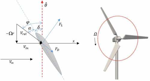
The focus of this study is lift-based turbines (Mendoza, Citation2018). Figure illustrates the acting forces and velocity on a typical VAWT; while Figure indicates that of a HAWT. The torque of the turbine is mainly generated by the lift force FL and on the contrast the drag force FD causes loss. Here, the normal force FN which is reluctant of aerodynamic forces in the radial component; while the tangential force FT is directly applied on the torque during one revolution (Mendoza, Citation2018):
Figure 2. Force and velocity vector acting on the cross section of a VAWT blade
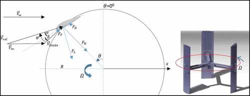
Figure 3. Force and velocity vector acting on the cross section of a HAWT blade, is the tangential direction of the blade
where NB is the number of blades, r is the radius of the turbine and is the average tangential force. The relative velocity flow Vrel and the angle of relative wind
can be defined by the relation between the tangential velocity of the blade Vblade and the incoming flow Vin, which is generally smaller than the asymptotic freestream velocity
(Mendoza, Citation2018):
where Vblade is given by .
The angle of the relative wind which is the sum pitch angle and angle of attack
is defined by (Mendoza, Citation2018):
The other important operational parameter for a wind turbine is a tip speed ratio (TSR) that is determined as the speed of a blade tip and the asymptotic flow velocity (Claessens, Citation2006):
Finally, the tangential force can be calculated by (Mendoza, Citation2018):
2.2. Vertical blades design
Recently, wind energy researches have shifted their interest and focus on VAWT as it can catch the wind from all directions, especially near ground turbulence flow. Moreover, it is quieter in operation and easier for maintenance. In this paper, the straight-bladed Darrieus wind turbine is considered which is mainly powered by lift force and can start up the turbine easily under lower wind speed. It takes the advantages of the lightweight, good balance, simple structure and high wind power coefficient (Shahzad, Asim, Mishra, & Paris, Citation2013).
It is noticed that the airfoil geometry is one of the major contributors to the wind turbine performance. Fernández (Meana-Fernández, Solís-Gallego, Fernández Oro, Argüelles Díaz, & Velarde-Suárez, Citation2018) studied the impact of thickness and camber of 4-digit NACA airfoils on the performance of a VAWT. First, how the airfoil thickness of the symmetrical NACA00xx blade affects the VAWT performance. It is shown that thicker airfoil is easier for starting the turbine and catch higher power output. However, the increase of thickness will become detrimental to the turbine performance due to the development of drag forces on the blades that can reduce the power captured from the wind. The value of thickness should fall between 15% and 21%. Moreover, the impact of the camber on the turbine performance is also considered. It is concluded that the performance of a wind turbine can be enhanced by adding a small amount of camber.
From the experiments conducted by Hsieh, et al. (Hsieh, Miao, Lai, & Tai, Citation2012), under the condition of wind speed lower than 13.5 m/s, NACA 6422 has better power output than symmetrical airfoil such as NACA 0022. In addition, NACA 6422 also decreases the cut-in speed by 33% comparing to other kinds of airfoil.
Castelli (Castelli, De Betta, & Benini, Citation2012) made more study and helped to determine the suitable number of blades using for a VAWT, where three- to five-blade configurations are considered. By taking the power coefficient of the three-bladed turbine as a reference, there is a 5% decrease in performance from the four-bladed turbine and a 15% decrease from the five-bladed turbine. Thus, in this project, the three-bladed wind turbine with NACA 6422 airfoil is considered in the design of a small complex wind turbine.
2.3. Horizontal blades design
In the small scale lift-type HAWT, some dedicated airfoils were used at a low angle of attack (AoA) where the lift coefficient must be much higher than the drag coefficient. Thus, the selection of suitable airfoil is dependent on the operating conditions relating to the Reynold number and aerodynamic behavior. This work focuses on the small scale wind turbine with low wind speed, and low Reynold number, so S series from NREL are favorable to choose (Miley, Citation1985).
The National Renewable Energy Laboratory (NREL) developed several groups of airfoils for the use of horizontal axis wind turbines (Elliott, Citation2000). NREL S-series airfoils can be divided into thin and thick families for the root to the tip of a turbine blade. S823 is the thickest airfoil which usually used for the root section of the section; while S822 is often considered for the blade tip design (Somers, Citation2005). Based on the intended size of the wind turbine and the purpose of development, the airfoil S833 series is selected for use. It is usually used in the middle section of a wind turbine blade.
Despite the NREL series of blades being smaller maximum power coefficient than NACA series, they can enhance a large range of tip-speed ratios while operating in more efficient scenarios.
3. Methodology
3.1. Experiment model
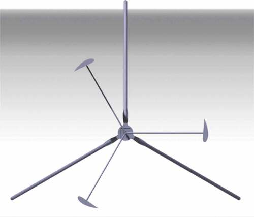
For the VAWT in this experiment, 3D printing takes a crucial role to implement. The vertical and horizontal blades of this complex system are all made by 3D printing. Therefore, the production cost is much lower in the developing phase comparing to other manufacturing methods. Before putting 3D printing into fabrication and implementation, computer modeling is essential as shown in Figures and .
Figure 4. Turbine demonstration using CATIA V5
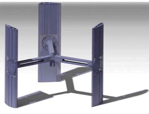
Figure 5. VAWT model demonstration using CATIA V5
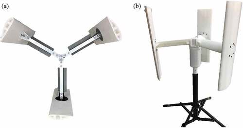
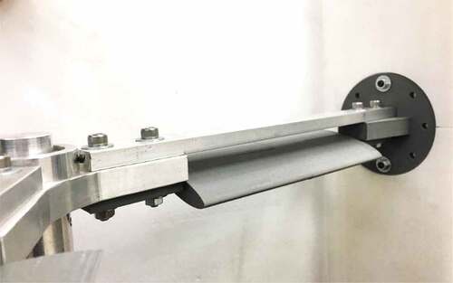
A DC motor will be selected in this project to generate electric power for use. Meanwhile, the main axis hub for the wind turbine is made of aluminum for the structure supporting. Lastly, the foundation for the VAWT is a redesign camera tripod (Brusca, Lanzafame, & Messina, Citation2014; Wahl, Citation2007). The actual experiment model for the test is shown in Figure as a reference.
Figure 6. Turbine blade structure of the experiment model
The experimental apparatus consisted of an optical tachometer, an anemometer, a simplified wind tunnel, and a multi-meter. The schematic diagram is shown in Figure .
Figure 7. Schematic diagram of the experiment
3.2. Qualitative tests
3.2.1. Blades geometry
For the complex airfoil selection for the blades, this project chooses NACA 6422 as its vertical wind turbine blades and NREL S833 for its horizontal wind turbine blades. Vertical blades are set in a fixed angle of attack, while horizontal blades are set as a variable in experiments. There are three types of airfoils for horizontal blades, Chord 75 mm with AoA −15° and AoA −30° along with Chord 120 mm with AoA −15°, as shown in Figure .
Figure 8. AoA setting in the horizontal blade of complex airfoil
In addition, the selected airfoils were simulated via Autodesk Flow Design. It is used to study the flow condition through different airfoil shapes. For the vertical blades, NACA 6422, velocity and pressure profile graph are shown respectively in Figures and 1. For the horizontal blades, S833, the velocity profile graph is shown in Figures and 1 under different AoA conditions.
Figure 9. Velocity profile of NACA 6422 in AoA = 0°
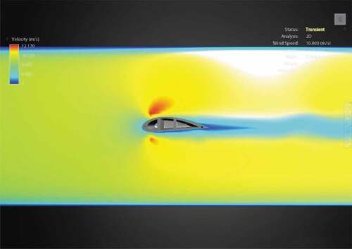
Figure 10. Pressure profile of NACA 6422 in AoA = 0°
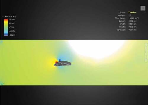
Figure 11. Velocity profile of S833 in A0A = −15°
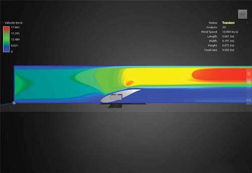
Figure 12. Velocity profile of S833 in AoA = −30°
3.2.2. Wind tunnel testing
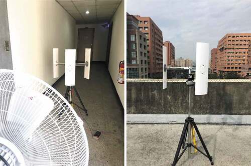
Due to the size of this H-rotor complex airfoil wind turbine, it does not fit the low-speed wind tunnel facility in the Department. Under such circumstances, a similar environment is chosen to conduct the testing. By using a 24-inch size industrial fan as the wind source which can blow up to 8 m/s wind speed, the wind turbine is set up at a rectangular hallway to form a wind duct and the roof tests are conducted. This experimental setup is shown in Figure .
Figure 13. Demonstration of simplified wind tunnel test and real site roof test
3.2.3. Performance testing
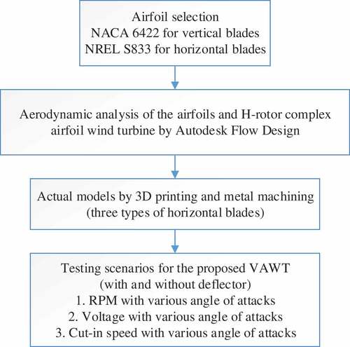
Two kinds of experiments are conducted to verify the performance of the proposed complex airfoil system. The experiment applies air deflectors to simulate the condition at the rim of the rooftop and the other one without it. Three different performance tests are also conducted in each scenario as (1) RPM of VAWT in various AoA conditions of the horizontal blades, (2) Voltage output of VAWT in various AoA conditions of the horizontal blades, (3) Cut-in speed of VAWT in various AoA conditions of the horizontal blades. The comparison charts are summarized to demonstrate the efficiency of adding the horizontal blades to the struts of the VAWT. The flowchart in Figure indicates the overall procedure conducted in this study from airfoil selection to real tests of the designed models.
Figure 14. Flowchart of the H-rotor complex airfoil VAWT design
4. Results
4.1. VAWT in conventional setup
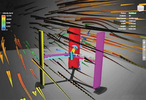
Before completed complex airfoil VAWT was assembled by the idea of design, computer modeling was made for analysis. Also, velocity and pressure profile graphs were simulated in order to study the effect of the complex airfoil. In this scenario of setting VAWT at ordinary incoming flow, which is set that wind speed at 10 m/s, simulations were conducted and as shown in Figures –1.
Figure 15. Velocity profile of the complex airfoil VAWT
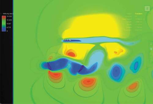
Figure16. Pressure profile of the complex airfoil VAWT
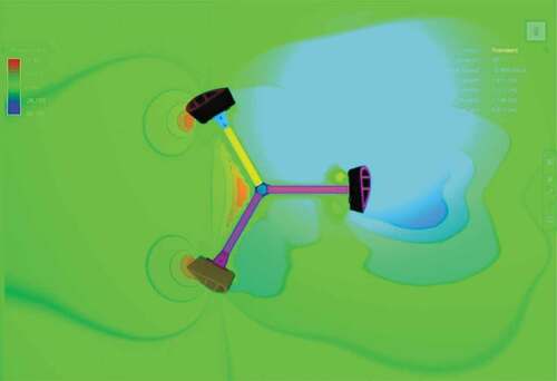
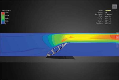
Figure 17. Demonstration of flow line through the complex airfoil VAWT
The results of the complex airfoil system performance under different scenario tests are shown in Figures –2. The performance of each AoA setting of the horizontal blades is compared through the charts along with the cut-in speed of VAWT.
Figure 18. Performance of various AoA with RPM

Figure 19. Performance of various AoA with voltage
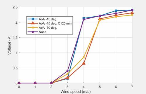
Figure 20. Cut-in speed Comparison
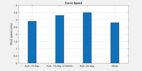
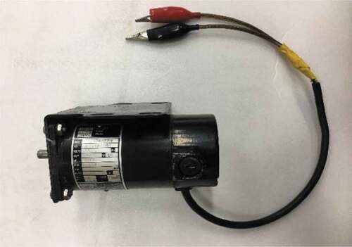
Figure 21. 20 W DC motor for generation
RPM of VAWT in various AoA conditions of horizontal blades.
Voltage output of VAWT in various AoA conditions of horizontal blades, using a small DC generator in Figure .
Cut-in speed of VAWT in various AoA conditions of horizontal blades.
The H-rotor complex airfoil VAWT is operated in an ordinary setup. The complex airfoil design does not contribute to small system efficiency. On the contrary, the design may have hindered the rotation of the VAWT. Consequently, the horizontal blades lead to result in lower its cut-in speed of the VAWT due to its increasing contact surface with the incoming flow. This is verified with the most remarkable contribution of the proposed complex airfoil design.
4.2. VAWT with deflector
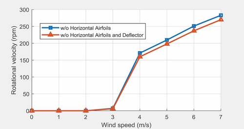
A deflector is added to the VAWT to simulate the conditions at the rim of the rooftop. Upward wind does usually blow at low altitude from the ground. By changing the wind direction upward, the horizontal blades can be driven. Therefore, it increases the rotating speed of the turbine and elevates its operation efficiency. Figures –2 shows the experiments with different conditions.
Figure 22. Performance comparison on AoA = −15°
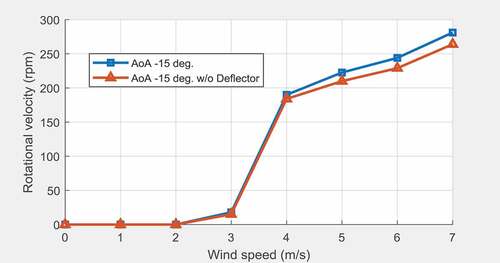
Figure 23. Performance comparison on AoA = −15° and Chord 120 mm
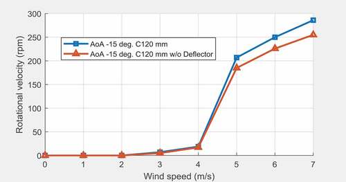
Figure 24. Performance comparison on AoA = −30°
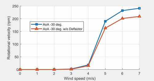
Figure 25. Performance comparison with and without horizontal blades
RPM of VAWT with horizontal blades in AoA = −15°
RPM of VAWT with horizontal blades in AoA = −15° and chord length 120 mm
RPM of VAWT with horizontal blades in AoA = −30°
RPM of VAWT without horizontal blades
From the test results, the best data of the complex airfoil turbine is shown to be able to rotate 286 rpm in the condition of the horizontal blades setting at AoA = −15° with its chord length of 120 mm. Table shows the maximum output rpm of the DC generator with each test scenario. In this table, four cases (1 ~ 4) and two conditions (A, B) result. The higher rpm refers to higher output power. By recording the rotating speed in this project, it is feasible to speculate the generation efficiency of this complex airfoil turbine.
Table 1. AoA and Chord length variable experiment
Based on the data acquisition from the experiments, a fixed aspect ratio (AR) scenario, which is 1.66 in this project, adding horizontal blades into the VAWT in a flat ground environment does not have a significant contribution to the efficiency. But it increases the stability of the wind turbine. However, in the condition of setting up the wind turbine at the rim of the rooftop, the complex airfoil does increase the efficiency of power output in certain conditions of AoA = −15° with chord length 120 mm. In addition, observing the experiment on a conventional VAWT, it shows that horizontal blades provide a down-force to stabilize the wind turbine and prevent falling from the gusty wind.
After a comparison between without/with deflector in the experiments, there is approximately 10% increase in efficiency in each scenario. As a comparison results in Table , the improvement with deflector is significant to reach 15%. The result from B3 to B2 reaches 18.7%. It receives the best output with system reliability in general. The most remarkable one falls in AoA = −15° with chord length 120 mm with deflector to capture the best wind generator operation near the ground. As a comparison on the same system setup, the merit behind the proposed complex airfoil may result that the larger contact area of the blades to vertical wind leads to greater force to rotate the turbine. This is important to small wind generators installing near the ground to capture upward wind gust with better operational efficiency.
5. Conclusion
This project aims to design, fabrication, and test the actual model of complex airfoil small scale wind turbines for applications in conditions corresponding to the low wind speeds and urban areas where wind gust is the major problem due to the ground effect and heat ventilation. To deal with the problems of vertical wind gust, the airfoil shape horizontal blades were mounted to the struts of the H-rotor wind turbine.
A series of quantitative and qualitative model tests were conducted in this paper to determine the wind turbine geometric parameters and evaluate its performance. Through many experiments based on the change of affecting parameters including AoA and chord length, the best geometry for the horizontal blades considered in this study has the AoA value of −15° with 120 mm chord length. In the case of adding the deflector to the tests considered as the working condition on the rooftop, there is an approximately 10 ~ 15% increase in performance. This means that the complex blade design is suitable for the use in near-ground wind conditions. In addition, wind tunnel testing reveals some unexpected aerodynamic effects that a down-force is derived to stabilize the wind turbine in operation.
The merit of the complex airfoil will be useful for small utility wind power sets in urban use. In the experiment system, there are some defects to improve in future works: (1) improve the roughness of the blade surface that causes significant drag resistance, (2) improve rotation part friction to get better rotation efficiency, (3) introduce higher performance DC generator for suitable power output. A design criterion shall be established to approach the best design with predetermined specifications. Finally, the foundation of the VAWT set should be redesigned and modified to keep off rain or dust.
Abbreviations
| VAWT: | = | Vertical-Axis wind turbine; |
| HAWT: | = | Horizontal-Axis wind turbine; |
| NACA: | = | National Advisory Committee for Aeronautics; |
| NREL: | = | National Renewable Energy Laboratory; |
| AoA: | = | Angle of Attack |
Nomenclatures
| = | Angle of attack (degree) | |
| = | Pitch angle (degree) | |
| = | Relative wind angle (degree) | |
| = | Blade azimuth angle (degree) | |
| = | Wind speed (m/s) | |
| = | Air density (kg/m3) | |
| A | = | Rotor blade area (m2) |
| P | = | Power (W) |
| Q | = | Torque (Nm) |
| h | = | Blade length (m) |
| n | = | Rotational velocity (rpm) |
| R | = | Rotor radius (m) |
| AR | = | Aspect ratio (-), h/R |
| NB | = | Number of blades |
| = | Angular velocity (rad/s) | |
| = | Tip speed ratio, | |
| CL | = | Lift coefficient |
| CD | = | Drag coefficient |
Additional information
Funding
Notes on contributors
Chin E. Lin
Chin E. Lin has been working as a professor in the Department of Aeronautics and Astronautics of National Cheng Kung University. He is also the director of UAV Center at Chang Jung Christian University. His research interest includes control system, aviation avionics system, mobile communication, CNS/ATM, and renewable energy control system.
Bao Chau Phan
Bao Chau Phan is a Ph.D. candidate in the Department of Aeronautics and Astronautics of National Cheng Kung University. He is working on the control system of the hybrid renewable energy system. His research interest consists of renewable energy systems, MPPT control, energy management, machine learning, and reinforcement learning.
Jia-Shian Chuang
Jia-Shian Chuang has graduated from the International Bachelor Degree Program on Energy in the Department of Aeronautics and Astronautics of National Cheng Kung University. He is a master student in the Faculty of Aerospace Engineering of Delft University of Technology (TU Delft). His research interest is renewable energy systems, aviation, and aerospace engineering.
Related Research Data
References
- Abe, K., Nishida, M., Sakurai, A., Ohya, Y., Kihara, H., Wada, E., & Sato, K. (2005). Experimental and numerical investigations of flow fields behind a small wind turbine with a flanged diffuser. Journal of Wind Engineering and Industrial Aerodynamics, 93(12), 951–17. doi:10.1016/j.jweia.2005.09.003
- Adaramola, M. (2014). Wind turbine technology: Principles and design (1st ed.). New York, NY: Apple Academic Press.
- Blackwood, M. (2016). Maximum Efficiency of a Wind Turbine. Undergraduate Journal of Mathematical Modeling: One+ Two, 6(2), 2. doi:10.5038/2326-3652.6.2.4865
- Brusca, S., Lanzafame, R., & Messina, M. (2014). Design of a vertical-axis wind turbine: How the aspect ratio affects the turbine’s performance. International Journal of Energy and Environmental Engineering, 5(4), 333–340. doi:10.1007/s40095-014-0129-x
- Castelein, D. (2015). Dynamic stall on vertical axis wind turbines: creating a benchmark of vertical axis wind turbines in dynamic stall for validating numerical models.
- Castelli, M. R., De Betta, S., & Benini, E. (2012). Effect of blade number on a straight-bladed vertical-axis darrieus wind turbine. World Academy of Science, Engineering and Technology, 61, 305–3011.
- Claessens, M. (2006). The Design and Testing of Airfoils in Small Vertical Axis Wind Turbines.
- Elliott, D. (2000). Philippines wind energy resource atlas development.
- Eriksson, S., Bernhoff, H., & Leijon, M. (2008). Evaluation of different turbine concepts for wind power. Renewable and Sustainable Energy Reviews, 12(5), 1419–1434. doi:10.1016/j.rser.2006.05.017
- Islam, M., Ting, D. S. K., & Fartaj, A. (2008). Aerodynamic models for Darrieus-type straight-bladed vertical axis wind turbines. Renewable and Sustainable Energy Reviews, 12(4), 1087–1109. doi:10.1016/j.rser.2006.10.023
- Liu, Z. (2015). Chapter 1 - Global Energy Development: The Reality and Challenges. In Z. Liu (Ed.), Global Energy Interconnection (pp. 1–64). Boston: Academic Press.
- Meana-Fernández, A., Solís-Gallego, I., Fernández Oro, J. M., Argüelles Díaz, K. M., & Velarde-Suárez, S. (2018). Parametrical evaluation of the aerodynamic performance of vertical axis wind turbines for the proposal of optimized designs. Energy, 147, 504–517. doi:10.1016/j.energy.2018.01.062
- Mendoza, V. (2018). Aerodynamic studies of vertical axis wind turbines using the actuator line model. (Doctoral thesis, comprehensive summary), Acta Universitatis Upsaliensis. (1671)
- Hsieh, W. C., Miao, J. M., Lai, C. C., & Tai, C. S. (2012). Experimental Study on Performance of Vertical Axis Wind Turbine with NACA 4-Digital Series of Blades. Advanced Materials Research, 488–489, 1055–1061. doi: 10.4028/www.scientific.net/AMR.488-489.1055.
- Miley, S. J. (1985). A catalog of low reynolds number airfoil data for wind turbine applications.
- Mohamed, M. H. (2012). Performance investigation of H-rotor Darrieus turbine with new airfoil shapes. Energy, 47(1), 522–530. doi:10.1016/j.energy.2012.08.044
- Mukinović, M., Brenner, G., & Rahimi, A. (2010). Analysis of vertical axis wind turbines. Paper presented at the New Results in Numerical and Experimental Fluid Mechanics VII, Berlin, Heidelberg.
- Panther, C., Wilhelm, J., Pertl, F., & Smith, J. (2009). Airfoil selection for a straight bladed circulation controlled vertical axis wind turbine.
- Pope, K., Dincer, I., & Naterer, G. F. (2010). Energy and exergy efficiency comparison of horizontal and vertical axis wind turbines. Renewable Energy, 35(9), 2102–2113. doi:10.1016/j.renene.2010.02.013
- Shahzad, A., Asim, T., Mishra, R., & Paris, A. (2013). Performance of a Vertical Axis Wind Turbine under Accelerating and Decelerating Flows. Procedia CIRP, 11, 311–316. doi:10.1016/j.procir.2013.07.006
- Somers, D. M. (2005). The S825 and S826 airfoils.
- Staelens, Y., Saeed, F., & Paraschivoiu, I. (2003). A straight-bladed varible-pitch VAWT concept for improved power generation.
- Wahl, M. (2007). Designing an H-rotor type wind turbine for operation on Amundsen-Scott South pole station (Independent thesis Advanced level (professional degree) Student thesis). Retrieved from http://urn.kb.se/resolve?urn=urn:nbn:se:uu:diva-162805DiVA database. (07030).