
 ?Mathematical formulae have been encoded as MathML and are displayed in this HTML version using MathJax in order to improve their display. Uncheck the box to turn MathJax off. This feature requires Javascript. Click on a formula to zoom.
Abstract
The cantilever vibrator motion system of a carbon nanotube (CNT) is considered the next step in developing cold cathodes for VHF-band nano-antennas. In cases where a nano-antenna is used in noisy environments, this device interferes with other communication devices. In this paper, both the mechanical oscillation and the field electron emission of the CNT cantilever are modeled using the Wiener model. A control method is proposed based on the Wiener model for tracking the reception–emission current and reference emission current of the nano-antenna receiver by transforming the nonlinear control system into a simple linear system with satisfactory performance. In the nano-antenna receiver, the Wiener model offers the suppression of undesirable interference signals and noise to reduce the tracking error between the reception and reference signals by controlling the applied DC voltage as a function of the tracking error. A numerical simulation is implemented to realistically reflect the theoretical results, which show the suppression of the interference noise signal as compared with the conventional control scheme.
PUBLIC INTEREST STATEMENT
Nano-devices are significantly small; therefore, the effects of gravity and inertia are minimal, and any weak electric fields can make waves in the nano-world. Nanotubes have amazing properties and vary in size and shape. Kenneth Jensen found that if one end of the carbon nanotube was fixed to a particular surface, a cantilever is created, when a molecule falls on the free end of the cantilever beam, the cantilever beam vibrates. These vibration frequencies cover certain commercial radio bands.
The field electron emission of CNT is modeled by using the Wiener model. A control scheme is designed based on this model to achieve accurate output tracking of the emission current. The complex nonlinear model is transformed into a simple linear model that can easily control the nonlinear system and show the best tracking accuracy. Subsequently, the efficiency of this model is evaluated through a numerical simulation.
1. Introduction
A carbon nanotube (CNT) comprises tubular lattice structures with remarkable optical, electrical, magnetic, and acoustic properties based on the nanoparticles, macroscopic quantum tunneling, quantum size, and small size features of the CNT surface (Bandaru, Citation2007). Introduced by Fowler and Nordheim in 1928 (Gan et al., Citation2019), electron field emission theory posits that when high voltage is applied between the bodies of two conductive materials, the potential energy of the electrons on the surface of the cathode and the vacuum region is lowered, and the thickness of the barrier is reduced. When the voltage exceeds a specific value, the thickness of the barrier becomes considerably small. Consequently, the electrons directly enter the vacuum through a tunnel barrier and are emitted from the cathode surface in large quantities instead of crossing the barrier height. This procedure serves as the basic mechanism of field emission (Matejčik et al., Citation2013). After Iijima performed electron microscopy studies on cathode deposits formed by graphite rod discharge in 1991, CNTs have received extensive research attention worldwide (Parmee, Collins, Milne, & Cole, Citation2015). CNT field emitters have the advantages of low threshold voltage, high emission current, large emission current density, stable emission current, and long life compared with conventional oxide field emitters. Nanotube field emitters are also used to construct devices that can be used in lighting (Bonard, Stöckli, Noury, & Châtelain, Citation2001; Saito, & Uemura, Citation2000; Chen, Zhang, Ma, Yao, & Zhang, Citation2012), plasma ignition, field emission x-ray tubes (Lei et al., Citation2015), and field emission displays (Lee et al., Citation2001; Lim, Lee, Lee, & Lee, Citation2007). However, when a nano-antenna is used in noisy environments, it interferes with other communication devices.
The antenna of an ordinary device receives a signal through an electromagnetic effect, that is, an electromagnetic wave generates an induced current in the antenna, but the antenna itself is always stationary. In a nano-antenna, the nanotube is an extremely thin, lightweight, and charged object, and the incident electromagnetic wave is sufficient to mechanically push it back and forth. A nano-antenna receiver can be implemented by utilizing the cantilever vibrator motion system of a CNT. The cantilever is designed in a rigid structure where a nanotube is fixed at one end and free at the other end (Verma, Singh, Chabbra, & Devi, Citation2018). These cantilevers have high sensitivity, selectivity, and fast responses. The desired signal is selected by the DC external voltage to detect input signals based on the current emitted from the tip of the CNT by adjusting the vibration of the CNT cantilever, and the interference signals are removed from the output. Accordingly, reducing the interference in nano-communication network systems has been studied by converting nano-electromagnetic modules into electric current and building a mechanical vibrator based on the principle of a nano-antenna (Feichtner, Selig, & Hecht, Citation2015). In nano-antennas, the VHF band is located at frequencies ranging from 30 MHz to 300 MHz, and the maximum data transmission efficiency is increased while reducing power consumption (Khuyen et al., Citation2017). A receiver that utilizes CNT nano-antenna with mechanical oscillations can reduce the path losses.
Several modeling methods of CNT were considered in previous contributions. These methods are briefly summarized in the present work. In (Giannopoulos, Kakavas, & Anifantis, Citation2008; Gupta & Batra, Citation2008; Papanikos, Nikolopoulos, & Tserpes, Citation2008), CNT was modeled as a structure with continuum properties, which can lead to neglect of the lattice structure. In (Mauricio & Srivastav, Citation2008), the transistors of field-effect type based on CNT were modeled. For single-walled carbon nanotubes (SWCNTs), both the nonlocal rod and nonlocal beam modeled were used to model all types of vibrations (Hu, Liew, & Wang, Citation2012). In (Khademolhosseini, Phani, Nojeh, & Rajapakse, Citation2012), a model based on a modified nonlocal continuum was investigated for SWCNTs. In (Narendar & Gopalakrishnan, Citation2012), nanostructures were analyzed and modeled by considering the flexural displacement method. In (Farhana, Alam, Motakabber, & Khan, Citation2013), an analytical model based on the energy dispersion relation was considered. In (Pal & Kumar, Citation2016), three modeling approaches, namely, equivalent continuum approach, quasi-continuum approach, and molecular dynamics, were considered. In (Paulson, Molaro, Bellisario, Strano, & Braatz, Citation2016), photovoltaic devices based on CNTs were modeled using predictive modeling. Moreover, in terms of controlling the mechanical vibration of a CNT-based antenna, several recent studies are summarized in the present paper. In (Tanaka, Ohno, & Tadokoro, Citation2015), the mechanical vibration of a CNT-based antenna was studied by presenting a simple model using the image charge technique. Angular sensitivity was shown to depend on the angle of arrival. In (Tanaka, Ohno, & Tadokoro, Citation2017), an adaptive control method of angular sensitivity for a nano-antenna was offered. This antenna is made of a single CNT cantilever engaged in a DC electric field. The activities of the antenna were analytically described using a singly clamped metallic sphere model and image charge method. Guidelines were imitative for the direction and shape of angular sensitivity. In (Ghaffoori & Abdul-Adheem, Citation2019), CNTs as a field emission electron supply were controlled by using an external applied DC electric field. The suggested control method was an appropriate technique for handling the field emission current. To achieve the controlling of the vibration for the nonlinear equation of the field emission current density of CNT cantilever, a classical PID control scheme was used as in (Du, Zhang, Li, & Jia, Citation2019; Meenakshipriya & Manikandan, Citation2015). Other advanced techniques can be considered, such as (Aouaouda & Chadli, Citation2019; Chadli, Maquin, & Ragot, Citation2002; Mohammed and Pierre, Citation2012; Rehan, Tufail, Ahn, & Chadli, Citation2017).
Several devices, including nano-antennas, have been widely applied in the field of radio communication. To achieve maximum transmission efficiency, the length of the dipole antenna must only be half of the wavelength at which the transmission is carried out (Nikolayev, Zhadobov, Karban, & Sauleau, Citation2018). A mechanical oscillator can collect radiation over a relatively large area and be applied to develop the circuitry of retrievers that use CNT. This idea is constantly evolving and has been applied in creating unique design methods for controlling the CNT cantilever vibrator of VHF nano-antennas (Lokman et al., Citation2017).
In this paper, a nano-antenna receiver based on a CNT cantilever vibrator motion system is considered, in which signal receiving includes unwanted interference noise signal. It is required to suppress noise interference by designing an appropriate control technique. This can be achieved by applying an external DC voltage to control mechanical oscillation and field electron emission of the CNT cantilever. The main contributions of this paper can be summarized as follows:
Based on the Fowler and Nordheim theorem, which is given in (Kyritsakis & Xanthakis, Citation2015), an analytic approach of vibrational motion and a quantitative equation for field emission is developed. The general expression of the damped oscillation amplitude of the cantilever motion as a function of a given driving force is carried out, which is linear in nature. Moreover, the field electron emission as a nonlinear function is derived to complete the modeling of the nano-antenna receiver.
The best available selected tool for modeling the nano-antenna receiver, which utilizing the CNT cantilever, is the Wiener model. This model includes linear dynamics and static nonlinearities in their received current outputs.
A control method is proposed based on the Wiener model to transform the composite nonlinear control system into a simple linear system in which the received signal is accurately tracking the transmitted signal by reducing the tracking error between both signals. The tuning of the received signal to the transmitting signal can be achieved by applying an external DC voltage to control mechanical oscillation and field electron emission of the CNT cantilever. This leads to suppress the interference noise signal.
The rest of this work is organized as follows. In section II, the theoretical background of vibrational motion and a quantitative equation for field emission are presented based on the Fowler and Nordheim theorem. Section III describes the proposed control method based on the Wiener model. Section IV discusses the simulation works. In section V, conclusion and future work of the paper are drawn.
2. Theoretical background
2.1. Field emission performance
The quantitative equation for field emission was first derived by Fowler and Nordheim (Kyritsakis & Xanthakis, Citation2015). Assume that a simple band of electrons, the points according to Fermi–Dirac statistics, the smooth surface of the metal plate, the classic mirror force, and the distribution of the work function are all uniform. Thus, the field emission quantitative equation for the derived metal can be formulated as (Zubair, Ang, & Ang, Citation2018)
where is the field emission current density,
is the emission surface electric field strength, and
and
are expressed constants with values of
and
, respectively.By integrating EquationEquation (1)
(1)
(1) , the field emission current density over the emitting surface A can be formulated as
Given that the Fowler–Nordheim (F–N) equation considers flat geometry conductors, the electron emission is given in EquationEquation (1)(1)
(1) , which is applied only in one dimension. We can obtain the following F–N relationship:
where is the voltage applied for the distance d between the anode and cathode. EquationEquation (3)
(3)
(3) shows that
and
should be linear for the field emission curve.
Figure shows the field emission test results obtained from the DC power supply test. Figure ) shows the field emission I–U curve, whereas Figure ) shows the corresponding F–N curve. For small measurements with 1, 2, and 3 µm electrode gaps of experimental data, the linearity relation, which is observed in Figure ), between and
is described in EquationEquation (3)
(3)
(3) (Bilici, Haase, Boyle, Go, & Sankaran, Citation2016).
Figure 1. Field emission characteristics obtained from the DC test: (a) current–voltage plot and (b) F–N plot
Accordingly, the field amplification factor can be obtained from the slope M of the linear F–N plot.
is related to density, cantilever tube length, cantilever electron work function φ through the emitter material, and surface electric field strength for the conductor of CNTs (Krüger, Lemell, Wachter, Burgdörfer, & Hommelhoff, Citation2018). Therefore, we have
The field enhancement factor of a single nanotube is determined by its aspect ratio , where h and r denote the length and diameter of the nanotube, respectively. Therefore, based on quantum mechanics, CNTs may have the expected field enhancement cantilever (Park et al., Citation2018), charge factor, and effective work function under a low electric field. The field emission performance is usually evaluated based on the field enhancement factor
, where
is the applied electric field and
is the local field strength at a certain point on the emitter surface where the field emission of CNTs is mainly affected by
(Cole et al., Citation2014).
2.2. Mechanical vibration
In accordance with F–N, β under analysis denotes experimental estimates that are well-defined constants for CNTs. These estimates are not necessarily expected for CNTs with considerably long or small radiuses. At a certain range of measured voltage and current, β can then be proportional for. Classical electrostatics guarantee that
at all points in space above it and at all points on the surface to ensure that the work function is uniform across the conductor surface. The maximum local field
points in the conductor surface are found at the apex or the hemisphere in a cylindrical post model that is used in parallel plane geometry.
The factor amplification of β, which is sensitive to cantilever shape, can be estimated by comparing this amplification factor with the α-aspect ratio. To measure the current variation of field emissions that can be modeled in the mechanical oscillations of CNTs during vibration, the amplification factor of the β (y) field amplifier must be measured while considering the cathode dimensions, anode system, and finite shape of the CNT hemisphere.
The Taylor series expansion for the amplification factor can be approximated as (Vincent et al., Citation2011)
where β0, β1, and β2 are equal to m − 1,
m − 2, and
m−3 and represent the local, first, and second spatial derivative constants, respectively. Meanwhile, the values of β0, β1, and β2 depend on the results of local electrostatic experiments.
Variations in β can lead to variations in the F–N equation for calculating the approximation field electron emission. The output current can be derived as
In this case, and
have constant values of
A V − 1 m − 1 and
Vm−1, respectively.
Based on the mechanics structural model, a vibrational analysis approach is developed where the parameters obtained from the mechanic’s force fields for CNT interactions are used to study the atomic structure and mechanics of CNTs.
For small displacement y, the cantilever is modeled as a linear mass–damper–spring dynamic that is driven by y-direction external force applied to the cantilever, where
denotes the electric field, and
denotes the induced charge. The driving force is described differently when the cantilever is in the solution or ambient conditions and can be expressed as (Tanaka et al., Citation2017)
where is the charge on the cantilever,
is the field intensity,
is the resonant frequency,
is the quality factor,
is the local field amplification factor,
is the first spatial derivative,
is the second spatial derivative, A and B are constants,
is the DC voltage,
is the CNT mass, and
is the spring constant. The values of these parameters are
C,
V/m,
=
Hz,
=
,
V,
=
g, and
=
kg/s2, which are based on a previous study (Tanaka et al., Citation2017).
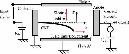
Figure illustrates a general technique for determining the expression scans of the damped oscillation amplitude as a function of the cantilever for a given driving force. The cantilever motion is carried out by integrating the equation steady state of motion for a damped harmonic oscillator at each scan point on the cantilever and given as (Tanaka et al., Citation2015)
where Vdc is the applied voltage between the plates A and A’. The electric field e impinges on the charged tip of the CNT, which represents the cathode. This voltage induces a charge—q at the tip of the CNT. The tip is subjected to a force due to the Coulomb interaction between the charge—q and the external DC electric field components Ec and Ev, causing CNT to vibrate under the influence of x- and y-directional forces Fx and Fy. The field emission current vibration is detected from the cathode to the anode by using the current detector. The equilibrium position of the tip in the y-direction has a positive and negative value depending on the DC electric field. This offset drastically changes the direction of the CNT tip.
Figure 2. The general analytical technique applied in the DC electric field
2.3. Wiener model
In the field of radio communication, a receiver that utilizes CNT nano-antenna with mechanical oscillations is widely used. Therefore, an accurate mathematical nonlinear model is required in modeling the CNT cantilever and processing field electron emission, which improves the ability to design a precise control scheme (Tang, Han, Liu, & Guan, Citation2016). Given their nonlinearity, linear systems are not always suitable for modeling practical systems. In case the nonlinearity is static, and the dynamics are linear, the most appropriate model is the Wiener model, which has an output that demonstrates a certain nonlinearity (Kulkarni, Talange, & Mate, Citation2019). This model is illustrated in Figure , in which the linear subsystem represents the modeling of the mass–damper–spring system or the equivalent elastic response of the cantilever with external force for a small displacement
. The F–N equation in EquationEquation (6)
(6)
(6) represents the nonlinear static function, which acts as the output function in the Wiener model.
Figure 3. Structure of the Wiener model for the CNT cantilever
In contrast to the general nonlinear model, the Wiener model is broadly used to model practical nonlinear systems, such as processes that include chemical reactions, due to its simplicity, ease of use, and stability (Hsu & Wang, Citation2009; Song, Oh, Park, Rhee, & Yoo, Citation2006).
3. Proposed control scheme
Based on the Wiener model, a linear proportional integral derivative (PID) controller is built to control the nonlinear model of the field electron emission for CNT. The key idea of this controller is to transform the composite model with a static nonlinearity function into a simple linear model. The block diagram of the proposed controller is shown in Figure .
Figure 4. Block diagram of the proposed control scheme
The F–N in EquationEquation (6)(6)
(6) has one-to-one mapping where the emission current
is expressed in terms of displacement
(Figure )). The approximate inverse of this static function is shown in Figure ). The approximate inverse nonlinear function of the F–N equation is used to implement the proposed control scheme illustrated in Figure . The reference emission current
passes through an approximate inverse nonlinear function of the F–N equation to obtain the reference displacement
, which is then compared with the actual displacement
of the CNT cantilever to generate the proposed displacement error
. The PID controller is constructed to perform an output tracking of the CNT cantilever displacement (
) to the reference displacement
to reduce the tracking error signal
in accordance with the following equation:
Figure 5. F-N equation: (a) versus
and (b) inverse of the nonlinear function given in EquationEquation (6)
(6)
(6)
4. Numerical simulations
To demonstrate the superiority of the proposed PID control scheme based on the Wiener model, a classical PID control scheme is used as a control technique for controlling Wiener systems (Du et al., Citation2019; Meenakshipriya & Manikandan, Citation2015). The classical controller is shown in Figure . A numerical simulation is performed for both schemes by using MATLAB®/SIMULINK® (Figure ).
The displacement error for the classical PID control scheme is , and the control signal
is produced from the PID controller as follows:
Figure 6. Block diagram of the classical control scheme
Figure 7. Implemented MATLAB®/SIMULINK® block diagram: (a) the proposed PID control scheme and (b) the conventional PID control scheme
The simulation results for both the proposed and classical control schemes for tracking a reference emission current are shown in Figure . This reference emission current is expressed as
The tracking error for both control schemes is illustrated in Figure .
Figure 8. Results of the numerical simulations: (a) the proposed scheme and (b) the classical PID control scheme
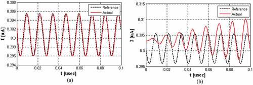
Figure 9. Tracking error e(y) with respect to : (a) the proposed scheme and (b) the classical PID control scheme
Using a PID controller within the classical control scheme in which the Wiener model is not considered part of the design will introduce insufficient output tracking. This behavior is observed from the numerical simulation results presented in Figure ). By contrast, the proposed control scheme that considers the controller design provides an accurate output tracking of the reference emission current, as illustrated in Figure ). This behavior can also be observed in Figure , where the dynamic range of the tracking error in the case of the classical control scheme is , which is small compared with
during the transient period and
during the steady-state. This response can be ascribed to the consideration of static nonlinearity in the design of the control scheme, which reduces the system into a linear system by using the inverse of the F–N static function. In nano-antenna communication systems, the proposed control scheme supports the CNT cantilever to suppress interference signals.
To demonstrate the effect of the interference signals, a random signal is added to the measured current in the form of Gaussian random signal with variance equal to . A numerical simulation is performed for both schemes by using MATLAB®/SIMULINK® (Figure ). In Figure , the simulation results for both the proposed and classical control schemes for tracking a reference emission current are shown. The current tracking error for both control schemes is illustrated in Figure .
Figure 10. Results of the numerical simulations: (a) the proposed scheme and (b) the classical PID control scheme
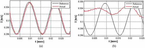
Figure 11. Tracking error e(I) with respect to : (a) the proposed scheme and (b) the classical PID control scheme
Similar to the first numerical simulation, insufficient current tracking was observed from using the PID controller within the classical control scheme as compared with the proposed control scheme (Figure ). In addition, Figure shows the current tracking error between the actual and the reference measured current. These results reflect the ability of the proposed control scheme to suppress the interference noise signal compared with the conventional scheme.
5. Conclusion
In this paper, a nano-antenna receiver based on a CNT cantilever vibrator motion system is considered, in which signal receiving can be achieved by applying an external DC voltage to control mechanical oscillation and field electron emission of the CNT cantilever. Moreover, the unwanted interference signal is removed from the output signal. The field electron emission of CNT is modeled by using the Wiener model. A control method is proposed based transforming the composite system into a simple linear model in which the received signal is accurately tracking the transmitted signal by reducing the tracking error between both signals. Subsequently, the efficiency of this model is tested through a numerical simulation.
As a future effort, the values of the controller parameters,
, and
given in EquationEquation (9)
(9)
(9) maybe tuned to obtain optimal performance as in (Abdul-adheem, Shalash, & Ghaffoori, Citation2017). Moreover, the complete controlled model may be tested within a communication system that includes a modulation techniques, like the one given in (Ghaffoori, Citation2019).
Additional information
Funding
Notes on contributors

Ali Jasim Ghaffoori
Ali Jasim Ghaffoori received the B.Sc. degree (with highest honors) in electrical engineering from the University of Technology at Baghdad in 1995, and he received the M.Sc. degree in Electrical and communication engineering from the University of Technology at Baghdad in 2004. His research interests include signal processing, Electrical, and communication.
Wameedh Riyadh Abdul-Adheem
Wameedh Riyadh Abdul-Adheem received the B.Sc. degree (with highest honors) in electrical engineering from the University of Baghdad at Baghdad in 1998, and he received the M.Sc. degree in computer and control engineering from the University of Baghdad at Baghdad in 2001, and Ph.D. degree in computer and control engineering at the University of Baghdad at Baghdad in 2019. His research interests include signal processing, nonlinear control, and optimization.
Related Research Data
References
- Abdul-adheem, W. R., Shalash, N. A., & Ghaffoori, A. J. (2017). Optimal full state feedback controller for two DC motor configurations with buck chopper. Eurasian Journal of Analytical Chemistry, 13(3), 278–12.
- Aouaouda, S., & Chadli, M. (2019). Robust fault tolerant controller design for Takagi- Sugeno systems under input saturation. International Journal of Systems Science, 50(6), 1163–1178. doi:10.1080/00207721.2019.1597941
- Bandaru, P. R. (2007). Electrical properties and applications of carbon nanotube structures. Journal of Nanoscience and Nanotechnology, 7, 1239–1267. doi:10.1166/jnn.2007.307
- Bilici, M. A., Haase, J. R., Boyle, C. R., Go, D. B., & Sankaran, R. M. (2016). electrode gaps at atmospheric pressure The smooth transition from field emission to a self-sustained plasma in microscale electrode gaps at atmospheric pressure. Journal of Applied Physics, 119(22), 1–9. doi:10.1063/1.4953648
- Bonard, J. M., Stöckli, T., Noury, O., & Châtelain, A. (2001). Field emission from cylindrical carbon nanotube cathodes: Possibilities for luminescent tubes. Applied Physics Letters, 78(18), 2775–2777. doi:10.1063/1.1367903
- Chadli, M., Maquin, D., & Ragot, J. (2002). Static output feedback for Takagi-Sugeno systems: An LMI approach. 10th mediterranean conference on control and automation MED2002 (pp. 1–7). Lisboa, Portugal: MED'2002At.
- Chen, G., Zhang, L., Ma, H., Yao, N., & Zhang, B. (2012). Carbon nanotubes cathode of field emission lamp prepared by electrophoretic deposition. Energy Procedia, 16, 240–243. doi:10.1016/j.egypro.2012.01.040
- Cole, M. T., Teo, K. B. K., Groening, O., Gangloff, L., Legagneux, P., & Milne, W. I. (2014). Deterministic cold cathode electron emission from carbon nanofibre arrays. Scientific Reports, 4, 6–10.
- Du, J., Zhang, L., Li, J., & Jia, J. (2019). Multi-PI control of hammerstein-wiener systems. Chinese Control Conference, CCC (pp. 279–282). Guangzhou, China.
- Farhana, S., Alam, Z., Motakabber, S., & Khan, S. (2013). Design and development of a simulator for modelling carbon nanotube. 5th International Conference on Mechatronics (ICOM’13) (pp. 1–6). Kuala Lumpur, Malaysia.
- Feichtner, T., Selig, O., & Hecht, B. (2015). Plasmonic nanoantenna design and fabrication based on evolutionary optimization. Optics Express, 25(10), 10828–10842. doi:10.1364/OE.25.010828
- Gan, H., Zhang, T., Guo, Z., Lin, H., Li, Z., Chen, H., … Liu, F. (2019). The growth methods and field emission studies of low-dimensional boron-based nanostructures. Applied Sciences, 9(5), 1–17. doi:10.3390/app9051019
- Ghaffoori, A. J. (2019). Papr reduction in ofdm system using adaptive hybrid technique. IOP Conference Series: Materials Science and Engineering, 518(5). doi:10.1088/1757-899X/518/5/052021
- Ghaffoori, A. J., & Abdul-Adheem, W. R. (2019). Control of field electron emission for carbon nanotube via externally applied DC electric field. IEEE international conference on sensors and nanotechnology 2019 (pp. 8–11). doi:10.1186/s12912-019-0335-1
- Giannopoulos, G. I., Kakavas, P. A., & Anifantis, N. K. (2008). Evaluation of the effective mechanical properties of single walled carbon nanotubes using a spring based finite element approach. Computational Materials Science, 41(4), 561–569. doi:10.1016/j.commatsci.2007.05.016
- Gupta, S. S., & Batra, R. C. (2008). Continuum structures equivalent in normal mode vibrations to single-walled carbon nanotubes. Computational Materials Science, 43(4), 715–723. doi:10.1016/j.commatsci.2008.01.032
- Hsu, Y. L., & Wang, J. S. (2009). A Wiener-type recurrent neural network and its control strategy for nonlinear dynamic applications. Journal of Process Control, 19(6), 942–953. doi:10.1016/j.jprocont.2008.12.002
- Hu, Y.-G., Liew, K. M., & Wang, Q. (2012). Nonlocal continuum model and molecular dynamics for free vibration of single-walled carbon nanotubes. Journal of Nanoscience and Nanotechnology, 11(12), 10401–10407. doi:10.1166/jnn.2011.5729
- Khademolhosseini, F., Phani, A. S., Nojeh, A., & Rajapakse, N. (2012). Nonlocal continuum modeling and molecular dynamics simulation of torsional vibration of carbon nanotubes. IEEE Transactions on Nanotechnology, 11(1), 34–43. doi:10.1109/TNANO.2011.2111380
- Khuyen, B. X., Tung, B. S., Yoo, Y. J., Kim, Y. J., Kim, K. W., Chen, L.-Y., … Lee, Y. (2017). Miniaturization for ultrathin metamaterial perfect absorber in the VHF band. Scientific Reports, 7(March), 1–7. doi:10.1038/srep45151
- Krüger, M., Lemell, C., Wachter, G., Burgdörfer, J., & Hommelhoff, P. (2018). Attosecond physics phenomena at nanometric tips. Journal of Physics B: Atomic, Molecular and Optical Physics, 51(17), 172001. doi:10.1088/1361-6455/aac6ac
- Kulkarni, R. S., Talange, D. B., & Mate, N. V. (2019). Output estimation of solar Photovoltaic (PV) system. International Symposium on Advanced Electrical and Communication Technologies ISAECT 2018 – Proceedings (pp.1–6). Kenitra, Morocco.
- Kyritsakis, A., & Xanthakis, J. P. (2015). Derivation of a generalized fowler-nordheim equation for nanoscopic field-emitters. Proceedings of the Royal Society A: Mathematical, Physical and Engineering Sciences, 471(2174), 1–10. doi:10.1098/rspa.2014.0811
- Lee, N. S., Chung, D. S., Han, I. T., Kang, J. H., Choi, Y. S., Kim, H. Y., … Kim, J. M. (2001). Application of carbon nanotubes to field emission displays. Diamond and Related Materials, 10(2), 265–270. doi:10.1016/S0925-9635(00)00478-7
- Lei, W., Zhu, Z., Liu, C., Zhang, X., Wang, B., & Nathan, A. (2015). High-current field-emission of carbon nanotubes and its application as a fast-imaging X-ray source. Carbon New York, 94, 687–693. doi:10.1016/j.carbon.2015.07.044
- Lim, S. C., Lee, K., Lee, I. H., & Lee, Y. H. (2007). Field emission and application of carbon nanotubes. Nano, 02(02), 69–89. doi:10.1142/S1793292007000465
- Lokman, A. H., Soh, P. J., Azemi, S. N., Lago, H., Podilchak, S. K., Chalermwisutkul, S., … Gao, S. (2017). A review of antennas for picosatellite applications. International Journal of Antennas and Propagation, 2017, 1–17. doi:10.1155/2017/4940656
- Matejčik, Š., Klas, M., Radjenović, B., Durian, M., Savić, M., & Radmilović-Radjenović, M. (2013). The role of the field emission effect in the breakdown mechanism of direct-current helium discharges in micrometer gaps. Contributions to Plasma Physics, 53(8), 573–579. doi:10.1002/ctpp.201300032
- Mauricio, J., & Srivastav, A. (2008). Numerical modeling of the I-V characteristics of carbon nanotube field effect transistors. 40th Southeastern Symposium on System Theory (SSST). New Orleans, LA.
- Meenakshipriya, B., & Manikandan, S. (2015). Wiener model-based CDM-PI controller for pH neutralisation process. International Journal of Modelling, Identification and Control, 24(2), 127–137. doi:10.1504/IJMIC.2015.071889
- Mohammed, C., &Pierre, B. (2012). Multiple models approach in automation: Takagi- Sugeno fuzzy systems. John Wiley & Sons.
- Narendar, S., & Gopalakrishnan, S. (2012). A nonlocal continuum mechanics model to estimate the material property of single-walled carbon nanotubes. International Journal of Nanoscience, 11(1), 1–8. doi:10.1142/S0219581X1250007X
- Nikolayev, D., Zhadobov, M., Karban, P., & Sauleau, R. (2018). Electromagnetic radiation efficiency of body-implanted devices. Physical Review Applied, 9(2), 24033. doi:10.1103/PhysRevApplied.9.024033
- Pal, G., & Kumar, S. (2016). Modeling of carbon nanotubes and carbon nanotube-polymer composites. Progress in Aerospace Sciences, 80, 33–58. doi:10.1016/j.paerosci.2015.12.001
- Papanikos, P., Nikolopoulos, D. D., & Tserpes, K. I. (2008). Equivalent beams for carbon nanotubes. Computational Materials Science, 43(2), 345–352. doi:10.1016/j.commatsci.2007.12.010
- Park, S., Gupta, A., Yeo, S., Jung, J., Paik, S., Mativenga, M., … Ryu, J. (2018). Carbon nanotube field emitters synthesized on metal alloy substrate by PECVD for customized compact field emission devices to be used in X-Ray source applications. Nanomaterials, 8(6), 1–9. doi:10.3390/nano8060378
- Parmee, R. J., Collins, C. M., Milne, W. I., & Cole, M. T. (2015). X-ray generation using carbon nanotubes. Nano Convergence, 2(1), 1–27. doi:10.1186/s40580-014-0034-2
- Paulson, J. A., Molaro, M. C., Bellisario, D. O., Strano, M. S., & Braatz, R. D. (2016). Mathematical modeling and analysis of carbon nanotube photovoltaic systems. IFAC-PapersOnLine, 49(7), 442–447. doi:10.1016/j.ifacol.2016.07.382
- Rehan, M., Tufail, M., Ahn, C. K., & Chadli, M. (2017). Stabilisation of locally Lipschitz non-linear systems under input saturation and quantisation. IET Control Theory & Applications, 11(9), 1459–1466. doi:10.1049/iet-cta.2016.1424
- Saito, Y., & Uemura, S. (2000). Field emission from carbon nanotubes and its application to electron sources. Carbon New York, 38(2), 169–182. doi:10.1016/S0008-6223(99)00139-6
- Song, I. H., Oh, R. J., Park, M. J., Rhee, H. K., & Yoo, K. Y. (2006). Control of a continuous polymerization reactor by Wiener input/output data-based predictive controller with direct with direct inverse identification. Chemical Engineering Communications, 193(7), 782–800. doi:10.1080/00986440500267196
- Tanaka, H., Ohno, Y., & Tadokoro, Y. (2015). Angular Sensitivity of VHF-Band CNT Antenna. IEEE Transactions on Nanotechnology, 14(6), 1112–1116. doi:10.1109/TNANO.2015.2477813
- Tanaka, H., Ohno, Y., & Tadokoro, Y. (2017). Adaptive control of angular sensitivity for VHF-Band nano-antenna using CNT mechanical resonator. IEEE Transactions on Molecular, Biological and Multi-Scale Communications, 3(1), 24–32. doi:10.1109/TMBMC.2016.2640282
- Tang, Y., Han, Z., Liu, F., & Guan, X. (2016, Sep). Identification and control of nonlinear system based on Laguerre-ELM Wiener model. Communications in Nonlinear Science and Numerical Simulation, 38, 192–205. doi:10.1016/j.cnsns.2016.02.016
- Verma, M., Singh, B., Chabbra, V., & Devi, R. (2018). Vibration and displacement analysis of carbon nanotube based cantilever for NEMS applications. Proceedings of the 2nd international conference on communication and electronics systems, ICCES 2017 (pp. 391–394). Coimbatore, India.
- Vincent, P., Poncharal, P., Barois, T., Perisanu, S., Gouttenoire, V., Frachon, H., & Purcell, S. T. (2011). Performance of field-emitting resonating carbon nanotubes as radio-frequency demodulators. Physical Review B, 83(15), 1–9. doi:10.1103/PhysRevB.83.155446
- Zubair, M., Ang, Y. S., & Ang, L. K. (2018). Fractional fowler-nordheim law for field emission from rough surface with nonparabolic energy dispersion. IEEE Transactions on Electron Devices, 65(6), 2089–2095. doi:10.1109/TED.2017.2786020