
Abstract
Hip implants consist of a stem, femoral head, acetabular cup, and backing cup. There is a wide variety of sizes and lengths. Their adaptability is limited because of the inter-anatomical variations. There is no single fit-for-all implant design that satisfies the orthopedic requirement satisfactorily. In this work, the trapezoidal-shaped stem with three different cross-sections is considered. The femoral head size, acetabular cup thickness, backing cup thickness, and trunnion geometry were varied to arrive at the best possible combination. ANSYS R-19 was used to perform the static analysis. It is found that trapezoidal-shaped profile two has the least amount of stress and total deformation. The von Mises stresses were found to be higher when the femoral head size was between 32 mm to 40 mm in profile two. It was also observed that the femoral head with 24 mm has the least stress compared to higher head sizes. The maximum von Mises stress-induced in profile two was 141.0 MPa, the total deformation of 0.04436 mm and elastic strain of 7.6 × 10⁻⁴ mm/mm. Trunnion interface does not have a significant role with respect to the structural strength of the implant. From the findings of this study, it is inferred that profile two shaped stems with the femoral ball size of 36 mm, acetabular cup thickness of 2 mm and backing cup thickness of 1mm is best suited for the hip replacement. The major outcome of this study is the utilization of the DoE method to determine the optimized value of the implant.
PUBLIC INTEREST STATEMENT
Total hip replacement is one of the main advancements in health care. These implants as a service of fifteen to twenty years. After the life of implants, patients have to undergo revision surgery, which is again costly and timeconsuming procedure. Hence there is a need to increase the life expectancy of such implants.
In the current work, three different profiled trapezoidal-shaped hip implant is used to evaluate a good stem design. It is also considered varying key design features like femoral head, acetabular cup, and backing cup to know the ranges at which these implants perform significantly.
This paper provides insight into novel hip implant design and analysis using the FE technique and design of experiment.
Competing interests
The authors declare that they have no competing interests.
1. Introduction
Nowadays biomedical implants have gained significant traction for improving the quality of life (Bhat & Kumar, Citation2013). Total hip arthroplasty is one of the techniques used from way back from the early 19th century to replace the hip joint due to fractures or due to osteoarthritis(Gomez & Morcuende, Citation2005). It is popularly known as one of the best-advanced techniques in the health care of the 21st century(Chethan, Satish Shenoy, & Shyamasunder Bhat, Citation2018). The hip joint is a synovial joint connects the lower limb to the trunk and is the largest weight-bearing joint next only to the knee joint. It is composed of femur bone consisting of the femoral head which articulates into the acetabulum of the pelvic girdle(Chethan, Zuber, Bhat, et al., Citation2019a). The average length of adult hip bone being 45cms which is approximately ¼th of adult height(Pan, Citation1924). Hip joints assist in the transfer of load from the upper body to the lower abdomen (Jun & Choi, Citation2010). Its provision for various degrees of freedom namely flexion, extension, abduction, adduction, internal rotation, external rotation facilitates human movement such as jogging, running, walking(Mathukumar, Nagarajan, & Radhakrishnan, Citation2019). A natural hip joint is shown in Figure .
Figure 1. The natural hip joint (right hip). (a) Capsule removed anterior aspect, (b) showing the ligament. (Chethan et al., Citation2018)
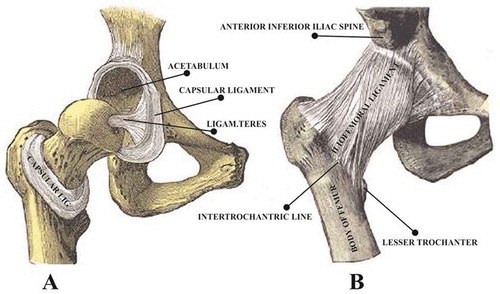
The healthy femur bone can withstand ten times to its body weight, beyond which it can lead to fracture(Chethan, Bhat, Zuber, & Shenoy, Citation2019). The total hip arthroplasty consists of implants made up of the stem, femoral head, acetabular cup and backing cup where the stem is inserted into the femur and femoral head is fitted over the stem by press-fit mechanism(Mattei, Di Puccio, Piccigallo, & Ciulli, Citation2011; Ihesiulor, Shankar, Smith, & Fien, Citation2015). The replaced hip joints are made up of biomaterials that comply with patient requirements. Currently, titanium-based alloys, chromium-based alloys, and ultrahigh molecular polyethylene are used widely used to manufacture these implants(Saini, Citation2015). The implants are usually patient specific which depends on the length of the femur, the diameter of the femoral head and the angle between femoral head to the femur. The size of the femoral head can vary from 22 mm to 54 mm depending upon specific human anatomy(Cho, Choi, & Kim, Citation2016). The femoral stems are available in many different geometrical designs such as straight, tapered, short length, and anatomical(Levadnyi, Awrejcewicz, Gubaua, & Pereira, Citation2017; Kim & Yoo, Citation2016). It has been reported in the various literature that these implants can last for ten years and less due to the extensive wear of materials (Watanabe et al., Citation2000; Huiskes & Chao, Citation1983; Rohlmann, Mössner, Bergmann, & Kölbel, Citation1983).
The inter-human anatomical variations make it extremely difficult to identify experimentally the correct combination of implants and material combinations. Several studies have popularly employed state-of-art Finite element analysis to evaluate implant designs with respect to load carrying capacity and geometrical modifications (Watanabe et al., Citation2000; Huiskes & Chao, Citation1983; Rohlmann et al., Citation1983). (Chethan, Zuber, Bhat N., et al., 2019) carried out an FEA study to evaluate the hip joint designs by using circular, ellipse, oval, trapezoidal designs. (Jiang, Citation2007) investigated four different structural models of artificial joints made of ultra-high molecular weight polyethylene (UHMWPE), CoCrMo alloy, 316L stainless steel, and Ti-6Al-4V alloy and their mechanical characteristics under static and dynamic conditions are investigated using finite element method (FEM). They have considered the femoral head of 28 mm diameter and acetabulum of thickness 8 mm. (Senalp, Kayabasi, & Kurtaran, Citation2007) investigated the static, dynamic and fatigue behavior of Ti–6Al–4V and cobalt-chromium metal materials and compared with stem shape developed by Charnley. (Yan, Berthe, & Wen, Citation2011) studied the effect of a porous titanium femoral prosthesis on bone remodeling. In another study, (Bah, Browne, Young, Bryan, & Xuan, Citation2011) applied joint reaction force acting on the greater trochanter and the load on the center of the femoral head. (Horak, Kubovy, & Horakova, Citation2011) utilized the force and kinematic conditions to develop the hip joint computational model.
The major issues with femur implant modeling and experimentation are the lack of standardization which makes comparison very difficult. Most studies only focused on changing the geometrical shapes and considered the loads lesser than ten times of body weight. Very few studies have adopted the ISO 7206–4:2010(E) and ASTM2996-F13 standards which provide specific guidelines to formulate boundary conditions and loads with respect to the length of the implant. The studies have reported different sizes of the femoral head, acetabular cup and backing cups being used(Chethan, Zuber, Bhat N., et al., Citation2019b). Moreover, there are many disagreements on the shape of the implant, material considerations and geometrical requirements (Kim & Yoo, Citation2016; Gabarre, Herrera, Ibarz, Mateo, & Gil, Citation2016). Our earlier works have shown that the trapezoidal-shaped implant made up of CoCr shows the best outcomes in terms of von Mises stresses (Chethan, Zuber, Bhat N., et al., Citation2019).
In the present study, a trapezoidal-shaped implant is designed with three different cross-sections and optimization of the design is accomplished using the design of the experiment [DOE] feature of Ansys R-19. The parameters varied were femoral head diameter, acetabular cups [liner], and backing cups [Shell]. In hip implant the stem remains the same, however, the femoral head size, liner thickness, shell thickness are varied as per the anatomy of the patient. So, in this study, a wide range of these parameters are considered to arrive at the best-suited stem profile with the optimum size of head, shell, liner which can be expected to have an extended life span.
2. Material and methods
The trapezoidal-shaped stem of length 180 mm is designed using CATIA V-6. Three different cross-sections “Profile one, Profile two & Profile three” with varying stem curvature is designed as shown in Figure . Profile one consists of a straight stem with the lateral side near the proximal end provided with a specific radius. In the case of Profile two, the diameter and arc length increases with an increase in the total angle between the lateral and medial side of the stem. Whereas, the profile three has the radius on the lateral side being completely removed and replaced with the cornered shoulder. In all the three profiles considered the neck and medial side dimensions remain constant.
Figure 2. (a) Three different cross-section designs of trapezoidal stems. (b) Illustration to demonstrate the trunnion for example, in a “12/14” taper
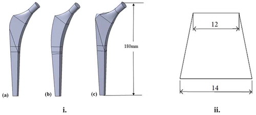
The femoral head, liner, and shell are kept constant for all the three stem models varying in cross-section. The trunnion is the taper junction into which the ball is attached with press-fit(Derar & Shahinpoor, Citation2015; Nassif et al., Citation2014; Bishop et al., Citation2013). Usually, this trunnion will be 12/14 mm. The cross-section of the taper trunnion is shown in Figure (b). Where 14 mm diameter at the bottom of the neck and 12 mm diameter at the top of the neck. The factors that affect the design performance of hip implants are the thickness of the liner, shell thickness, femoral head diameter, and the trunnion design. The femoral head diameter varies from 24 mm to 44 mm, the liner has a thickness from 2 to 10 mm, whereas the shell has thickness range from 1 to 4 mm (Saputra, Anwar, Jamari, & Van Der Heide, Citation2013; Tsikandylakis et al., Citation2018; López-López et al., Citation2017). These variations are necessary to accommodate the different anatomical considerations and cater to patient-specific requirements.
In this work, the trunnion bottom surface radius is kept constant at 7 mm and the top surface radius is varied from 3 mm to 6 mm at an interval of 0.5 mm. The boundary conditions are applied as per the ASTM2996-F13 standard and loading conditions considered are as per ISO 7206–4:2010(E) (ASTM, Citation2015). Table shows the key performance indicators which are considered for the static structural analysis carried out in this work. The results are analyzed to determine the best profile and identify the least stress-bearing design for the given boundary conditions.
Table 1. Different sizes of backing cup, acetabular cup, femoral head and trunnion top surface for the trapezoidal-shaped implant (Goebel et al., Citation2012) (Al-hamad, Duff, Takamura, & Amstutz, Citation2014) (Liu, Jin, Roberts, Grigoris, & Hospital, Citation2015)
This is made possible by the design of experiments [DOE] approach of Ansys R-19. In this work, CoC [ceramic on ceramic] is considered due to its excellent stress-bearing abilities and deformation (Chethan, Zuber, Bhat N., et al., Citation2019). Where all the components are considered as ceramic and the properties of the material of CoCr are given in Table .
Table 2. Mechanical properties of CoCr material (Palla, Group, & Gurunathan, Citation2011)
The mesh convergence study resulted in a 1 mm size mesh as the most suitable for unstructured mesh, with no significant changes in the results with mesh size lesser than 1 mm. Figure (a) shows the mesh convergence for the von Mises stress. The total number of nodes & elements obtained is 678,328 and 516,897 respectively.
Figure 3. (a) Variation of the stress values with a change in mesh size; (b) Boundary Condition Location for Hip Stem Length of 120 mm < CT < 250 mm (ASTM, Citation2015)
2.1. Boundary conditions
The boundary conditions are applied as per the ASTM F2996-13 and loading conditions are considered as per ISO 7206–4:2010(E)(ASTM, Citation2015). The fixation of the stem and load application is as shown in Figure (b). According to the standards, the modeled stems are bisected into three cross-sections from the top surface of the stem. The hip stem is cut from the center of the head as per the ISO 7206–4:2010(E) with the worst-case head/neck offset. The first cut is done 80 mm from the center of the top surface for depicting the stress distribution over the implant. A second cut is then made 10 mm below the first cut. The hip stem is constrained in all directions on all faces distal to the second cut. Constraining the stem in this manner ensures that excessive erroneous stresses are not generated at the region of interest due to the influence of rigid fixation. The remaining portion about 90 mm is the fixed support and is constrained in all degrees of freedom. Figure (b) shows the bisection of the model.
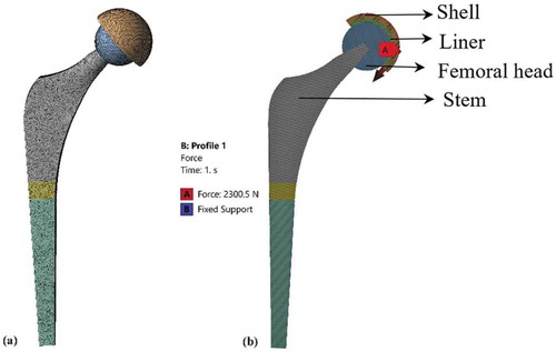
As per the standards, a static force of 2,300N is applied over the head of the implants. Figure (a) shows the discretized model of the complete hip implant(Chethan, Shyamasunder Bhat, Zuber, & Satish Shenoy, Citation2019b). Figure (b) shows the load applied and fixed boundary conditions as per the standards. Static structural analysis is carried out to evaluate the von Mises stresses and total deformation.
Figure 4. (a) Discretized hip implant model (b) Boundary conditions applied over the hip implant
The design of experiments is applied to the set of varying parameters to the fixed stem. The stem is kept constant and the other components like shell, liner and femoral head sizes are varied to know the effect of these parameters on the implants. The sizes which are considered for the study are shown in Table . In previous works usually, a set of the parameter with the fixed size is considered for the analysis, but nowhere DOE was applied to identify the best combination with a change in these parameters(Geramizadeh, Katoozian, Amid, & Kadkhodazadeh, Citation2018; Ur, Erdem, Haider, & Boccaccini, Citation2017).
3. Results
3.1. Static structural analysis of trapezoidal shaped hip implant
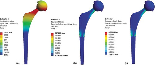
An initial model of the trapezoidal-shaped stem for profile one was analyzed using FEM analysis. The analysis was carried out for the constant femoral head size of 32 mm, liner thickness of 4 mm and shell thickness of 2 mm. The boundary conditions are applied as per the ASTM2996-F13 and loading conditions are considered as per ISO 7206–4:2010(E). The von Mises stress and total deformation along with elastic strain were evaluated. The total deformation was found to be 0.059 mm, von Mises stress of 207.2 MPa and equivalent elastic strain was 0.0011 mm/mm. Figure shows the total deformation, von Mises stress, elastic strain. Although the findings were almost similar to the previous studies with different types of boundary conditions, there is large variability in terms of geometrical parameters that are considered. There are several types of implants of various sizes and shapes that could be clinically used (Cho et al., Citation2016; López-López et al., Citation2017). There is no implant that could be employed one-fit-for-all and perfectly address the safety and durability considerations. In this work, an optimization study was carried out to (a) Study the inter-operable relationship between the size of the femoral head and trunnion taper radius, and (b) determine the best combination of the acetabular cup[liner] and backing cup[shell] sizes for reduced stresses and deformation.
Figure 5. (a) Total deformation, (b) von Mises stress, (c) Elastic strain
3.2. Effect of different sized femoral heads v/s varying the trunnion taper radius
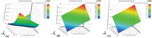
Trunnion which is usually 12/14 mm in diameter is the tapered junction of the stem where the femoral head resides (Baharuddin et al., Citation2014). In this study, the effect of different femoral head diameter and the varying taper size is studied for profile one, profile two and profile three. The femoral head comes with varying sizes of 24 mm to 54 mm depending upon the anatomy of the patient(López-López et al., Citation2017). In this work, the models developed have the femoral head changed from 24 mm to 44 mm at 4 mm intervals each. The shell thickness is kept constant of 2 mm and liner thickness is kept constant of 4 mm. The top surface of the trunnion was tapered from 12 mm to 6 mm while maintaining the bottom surface at 14 mm in diameter. This resulted in a total of 42 different possible combinations of implant designs as indicated in Table . Using the DOE feature of ANSYS R-19, all the combinations were analyzed at identical boundary conditions. Figure shows the response curve for the varying femoral head size to the trunnion top surface dimension for trapezoidal stem profile one.
Figure 6. Profile one varying with trunnion and femoral head (a) Total deformation (b) von Mises stress (c) Elastic strain
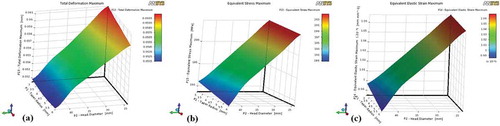
The variation in femoral head size resulted in a significant change in the total deformation, von Mises stress, and elastic strain. As the femoral head size increases there is a considerable decrease in the deformation, stress-induced in the implant and strain rate. The maximum von Mises stress developed was 203.0 MPa, maximum deformation was 0.0604 mm and an elastic strain of 1.06 × 10⁻³ mm/mm was observed for profile one. This was applicable for an implant having a 24 mm head with a 3 mm trunnion radius. The minimum values were obtained for profile one implant having a 44 mm head diameter and a trunnion of 6 mm taper radius.
The description of DOE findings for profile two is different from that of profile one. Figure shows the response curve for the varying femoral head size to the trunnion top surface dimension for trapezoidal stem having profile two.
Figure 7. Profile two varying with trunnion and femoral head (a) Total deformation (b) von Mises stress (c) Elastic strain
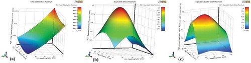
The von Mises stresses were found to be higher when the femoral head size is between 32 mm to 40 mm. It was also observed that the femoral head with 24 mm has the least stress compared to higher head sizes. The findings were similar for the elastic strain determined. The maximum von Mises stress-induced in profile two was 141.0 MPa, the total deformation of 0.04436 mm and elastic strain of 7.6 × 10⁻⁴ mm/mm. However, there is no significant variation in the total deformation values with the change in the trunnion radius.
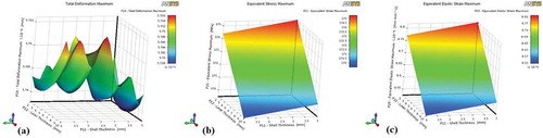
Figure shows the response curve for the varying femoral head size to the trunnion top surface dimension for trapezoidal stem profile three.
Figure 8. Profile three varying with trunnion and femoral head (a) Total deformation (b) von Mises stress (c) Elastic strain
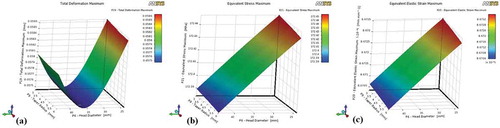
In the case of profile three, the stress and elastic strains decrease linearly with the increase in the femoral head size. The total deformation was found to be least at the head size of 36 mm and increased with a subsequent increase in the head size. The maximum total deformation was 0.0586 mm, von Mises stress was a maximum of 172.45 MPa and the elastic strain was observed at 8.6704 × 10⁻⁴ mm/mm. Another observation was that the total deformation was less for the 36 mm diameter femoral head.
In general, it was observed that profile two accounted for the lowest value of total deformation, von Mises stress and elastic strain with respect to variations in the femoral head size and change in trunnion shape. Among all the variations considered, the femoral head size of 36 mm and trunnion radius of 6 mm produced the best outcome and was consistent with all the profiles studied.
3.2.1. Effect of acetabular cup v/s backing cups on von mises stress
For this study, the femoral head was maintained constant at 36 mm diameter, and the trunnion was fixed at 12/14 mm. The liner and the shell thickness varied as shown in Table . The liner was varied from 2 to 10 mm at an interval of 2 mm and the shell cup was varied from 1 to 4 mm at an interval of 1 mm.
The total deformation, von Mises stress and elastic strain for profile one are shown in Figure .
Figure 9. Profile one with varying liner and shell thickness (a) Total deformation (b) von Mises stress (c) Elastic strain
It can be seen from the figure that the maximum total deformation of 0.0586, von Mises stress of 199.0MPa and elastic strain of 1.038 × 10⁻³ mm/mm was observed with 2 mm liner thickness and 4 mm shell thickness. The least value of deformation and von Mises stress was obtained with 10 mm of liner thickness and 4 mm of shell thickness.
Figure shows the total deformation, von Mises stresses and elastic strain for the profile two shaped stems. In the case of profile two, the maximum total deformation, von Mises, and elastic strain were 0.047 mm, 142MPa, and 7.96 × 10⁻⁴ mm/mm respectively. Moreover, it was determined that an implant with the lowest liner thickness and backing cup thickness has significantly reduced deformation and von Mises stress.
Figure 10. Profile two with varying liner and shell thickness (a) Total deformation (b) von Mises stress (c) Elastic strain
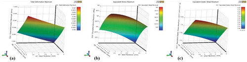
Figure shows the total deformation, von Mises stress and elastic strain for the profile three trapezoidal stems. The maximum value of total deformation, von Mises stress and elastic strain obtained were 0.0576 mm, 175MPa, and 8.81x10⁻⁴ mm respectively. It was also found that the total deformation was less when 8 mm liner was used against 1.5 mm shell. However, the von Mises stress and elastic strain recorded the lowest values when 10 mm liner is used against a 4 mm shell.
Figure 11. Profile three with varying liner and shell thickness (a) Total deformation (b) von Mises stress (c) Elastic strain
Thus, for the case where the liner thickness and shell were varied, profile three exhibited better outcomes when compared to the other profiles. In terms of quantifiable values of total deformation, von Mises stress and elastic strain, profile two shaped stem showcased the lowest values overall for both the studies.
4. Discussion
Hip implants are manufactured using different types of biomaterials and are available in various designs(Goldsmith, Dowson, Isaac, & Lancaster, Citation2000). The major problem with hip arthroplasty is that it can last only for about 10 years in active younger patients. Chromium cobalt, titanium alloys, ultra-high molecular polyethylene are the materials which are widely used in the hip implants. Several studies have carried out design changes to improve the implants especially the stem part(Senalp et al., Citation2007; Chao & López, Citation2007; Tanner et al., Citation1995). Some studies have suggested shorter stems, and others have adopted longer stems. In some studies, the profile of the stem was modified and analyzed(Abdullah, Asri, Alias, & Giha, Citation2010; Takai, Nakayama, Murayama, & Takahashi, Citation2019; Spinelli et al., Citation2012). Mamdouh et al. considered Titanium alloy 32 mm femoral head, 15 mm UHMWPE acetabular cup along with 1 mm backing cup. They found that stresses reduced due to the addition of backing cup(Monif, Citation2012). Yuan et al. studied the biomechanical effect of unilateral hip arthroplasty and observed a maximum total deformation of 0.68 mm after the surgery(Xin, Kim, & Yang, Citation2013). Griza et al. considered an implant of 175 mm length. They found the maximum von Mises stress of 285.1MPa acting on the stem when 2300N of the load was applied on the femoral head(Griza, Reis, Reboh, Reguly, & Strohaecker, Citation2008). Zanon et al. considered the stem length of 165 mm and applied the load as per ASTM F 745 standards. The maximum von Mises stresses of 210MPa were obtained at the lateral region of the stem(Griza et al., Citation2009). Ji-Yong Bae et al. studied the effect of different cross-section shaped modular stems along with femur bone including the pelvic. They applied a load of 1764MPa equivalent to three times the bodyweight of women and observed. The maximum stress of 185.7MPa was reported at the upper part of the stem and 110.0 MPa at the lower part of the stem(Bae et al., Citation2011). Kayabhasi et al. studied the effect of notching in the stem design. They have considered the femur bone along with the cobalt-chromium implant. They found the maximum von Mises stress of 193.4MPa(Kayabasi & Erzincanli, Citation2006). Hai-Bo Jiang et al. considered femoral head made up of stainless steel, Ti-6Al-4V and cobalt-chromium over UHMWPE liner, they observed the maximum total deformation 0.1 mm for stainless steel and 0.85 mm for cobalt-chromium when a load of 200N is applied over the center of the femoral head(Jiang, Citation2007).
In general, there is a wide range of choices in the selection of femur implants. This is further complicated by the patient to patient anatomical variations. There is no one-fit for all implants that can satisfy the conditions of structural strength for longer durability. von Mises stress greatly affects the life of the implant when continuous cyclic load associated with regular day to day activities is applied to the implant. Aseptic loosing is one of the major problems in the implants(Shi, Ajayi, Fenske, Erdemir, & Liang, Citation2003; Burger, de Vaal, & Meyer, Citation2007). Deformation greatly affects the loosening of the implant. Thus, in this work, trapezoidal stems with three different popular profiles were modeled and parametric changes were carried out using the design of the experiment option in Ansys 19. The key design features which greatly affect the implants are identified as shown in Table . Our previous studies have shown that the performance of cobalt- chromium implants to be more suitable than the other widely used biomaterials (Chethan, Zuber, Bhat N., et al., Citation2019).
An initial static analysis was performed for a standard femoral head size of 32 mm, liner thickness of 4 mm and backing shell thickness of 2 mm for all the three profiles. Profile two exhibited the least value of total deformation and von Mises stress compared to profile one and profile three. The maximum von Mises stress, total deformation and elastic strain for profile two were 207.2 MPa, 0.059 mm and 0.0011 mm/mm respectively. The values obtained in this study was comparatively lesser than those observed in previous literature (Jiang, Citation2007; Griza et al., Citation2009; Xin et al., Citation2013; Bae et al., Citation2011; Kayabasi & Erzincanli, Citation2006). In the study of hip implant design, patient anatomy is very vital in the choice of femoral head size, liner thickness, and shell thickness. Besides, it is difficult to conclude whether the implants so designed are optimum enough for different sizes. Design of experiments is a widely used method to arrive at an optimum value when several competing variables influence the choice of design. In order to determine, the best possible design outcome, two sets of optimization studies were carried out, (a) study the inter-operable relationship between the size of the femoral head and trunnion taper radius, and (b) determine the best combination of liner and shell sizes for reduced stresses and deformation. Using the DoE approach, a a femoral head diameter was varied from 24 mm to 44 mm at an interval of 4 mm each and the liner thickness varied from 2 to 10 mm at a interval of 2 mm and shell thickness is varied from the 1 to 4 mm at an interval of 1 mm. It was found that all the design analysed exhibited stresses and deformation well within the allowable design limit. Among all the profile studied, profile two with femoral head diameter of 36 mm, liner thickness of 2 mm and shell thickness of 1 mm exhibited the lowest von Mises stress of 139MPa. Moreover the deformation of profile two shaped stem has lowest deformation of 0.042 mm. None of the earlier studies have obtained stress value closer to the present finding (Griza et al., Citation2008; Griza et al., Citation2009; Bae et al., Citation2011; Kayabasi & Erzincanli, Citation2006). Also, the deformation value for the optimized implant determined using the DoE approach is lower than any of the previous studies (Jiang, Citation2007; Xin et al., Citation2013).
5. Conclusion
The hip implant is one of the commonly and widely used surgical procedures to overcome the pain associated with a fractured hip. The use of DoE is to evaluate different key parameters that are varied in the real condition and to come out with the best-suited size. Different types of stems are used with varying designs and sizes adapting to the patient’s anatomy. In this study, three different profiles of the cobalt-chromium stem are considered and analyzed using the design of experiment approach in ANSYS R-19. The acetabular cup, backing cup, and trunnion top surface radius and femoral head sizes are varied. It was observed that profile two shaped stem design has the least von Mises stress and total deformation values compared to profile one and profile three. Trunnion interface does not play a significant role with respect to the structural strength of the implant. The main outcome of this study is the utilization of the DoE method to determine the optimized value of the implant. The trapezoidal profile two with the femoral head of 36 mm diameter, 2 mm liner thickness, and 1 mm shell thickness resulted in the lowest von Mises stress and total deformation. Further, this approach can be applied to varying the materials used in implants. Also along with the implants, femur bone and ligaments can also be considered for the analysis.
Abbreviations
| UHMWPE | = | Ultra-high molecular weight polyethylene |
| CoCrMo alloy | = | Cobalt-chromium-molybdenum alloy |
| Ti-6Al-4V alloy | = | Alpha-beta titanium alloy |
| FEM | = | Finite element method |
| DOE | = | Design of experiments |
| CoC | = | Ceramic in Ceramic |
Authors’ contributions
Chethan.K.N, Satish Shenoy B and Shyamasunder Bhat N designed the project.
Chethan.K.N and Mohammad Zuber performed the analysis.
Chethan.K.N wrote the manuscript.
Shyamsunder Bhat N and Satish Shenoy B gave advice on writing article.
Satish Shenoy B, Mohammad Zuber reviewed the manuscript.
All authors read and approved the final manuscript before submitting it to the journal.
Consent for publication
All authors consent for the publication of this manuscript.
Ethics approval and consent to participate
An institutional ethical clearance has been obtained from Kasturba Medical College and Kasturba Hospital’s institutional ethical committee. [Registration No. ECR/146/Inst/KA/2013/RR-16].
Acknowledgements
The authors thank the Department of Aeronautical and Automobile Engineering, Manipal Institute of Technology, Manipal Academy of Higher Education, Manipal for providing the high computational facility to carry out this research.
Additional information
Funding
Notes on contributors

Satish Shenoy B
Chethan K N has been working as an Assistant Professor in the Department of Aeronautical and Automobile Engineering, Manipal Institute of Technology, Manipal Academy of Higher Education, Manipal, Karnataka, INDIA. His area of interest includes Biomechanics of the hip joint, Finite element analysis of biomedical implants, Composite materials, and Manufacturing of medical implants. The author has published articles related to finite element analysis of hip implants, mechanical characterization of materials and composite materials.
Related Research Data
References
- Abdullah, A. H., Asri, M. N. M., Alias, M. S., & Giha, T. (2010). Finite element analysis of cemented hip arthroplasty: Influence of stem tapers.
- Al-hamad, M., Duff, J. M., Takamura, K. M., & Amstutz, H. C. (2014). Acetabular component thickness does not affect mid-term clinical results in hip resurfacing. Clinical Orthopaedics and Related Research, 1528–14. doi:10.1007/s11999-014-3468-2
- ASTM. (2015). Standard Practice for Finite Element Analysis (FEA) of non-modular metallic orthopaedic hip femoral stems 1. Astm, (August 2013). doi:10.1520/F2996-13.Copyright
- Bae, J. Y., Farooque, U., Lee, K. W., Kim, G. H., Jeon, I., & Yoon, T. R. (2011). Development of hip joint prostheses with modular stems. CAD Computer-Aided Design, 43(9), 1173–1180. doi:10.1016/j.cad.2011.05.004
- Bah, M. T., Browne, M., Young, P. G., Bryan, R., & Xuan, V. B. (2011). Effects of implant positioning in cementless total hip replacements. Computer Methods in Biomechanics and Biomedical Engineering, 14(SUPPL.1), 275–276. doi:10.1080/10255842.2011.595241
- Baharuddin, M. Y., Salleh, S. H., Zulkifly, A. H., Lee, M. H., Noor, A. M., A Harris, A. R., … Abd Kader, A. S. (2014). The design process of the cementless femoral stem using a nonlinear three-dimensional finite element analysis. BMC Musculoskeletal Disorders, 15(1), 1–17. doi:10.1186/1471-2474-15-30
- Bhat, S., & Kumar, A. (2013). Biomaterials and bioengineering tomorrows. Biomatter, 3(September), 1–12. doi:10.4161/biom.24717
- Bishop, N., Witt, F., Pourzal, R., Fischer, A., Rütschi, M., Michel, M., & Morlock, M. (2013). Wear patterns of taper connections in retrieved large-diameter metal-on-metal bearings. Journal of Orthopaedic Research, 31(7), 1116–1122. doi:10.1002/jor.22326
- Burger, N. D. L., de Vaal, P. L., & Meyer, J. P. (2007). Failure analysis on retrieved ultra-high molecular weight polyethylene (UHMWPE) acetabular cups. Engineering Failure Analysis, 14(7), 1329–1345. doi:10.1016/j.engfailanal.2006.11.005
- Chao, J., & López, V. (2007). Failure analysis of a Ti6Al4V cementless HIP prosthesis. Engineering Failure Analysis, 14(5), 822–830. doi:10.1016/j.engfailanal.2006.11.003
- Chethan, K. N., Bhat, S. N., Zuber, M., & Shenoy, S. B. (2019). Patient-specific static structural analysis of femur bone of different lengths. The Open Biomedical Engineering Journal, 12(1), 108–114. doi:10.2174/1874120701812010108
- Chethan, K. N., Satish Shenoy, B., & Shyamasunder Bhat, N. (2018). Role of different orthopedic biomaterials on wear of hip joint prosthesis: A review. Materials Today: Proceedings, 5(10), 20827–20836. doi:10.1016/j.matpr.2018.6.468
- Chethan, K. N., Shyamasunder Bhat, N., Zuber, M., & Satish Shenoy, B. (2019b). Finite element analysis of different hip implant designs along with femur under static loading conditions. Journal of Biomedical Physics and Engineering, May, 507–516. doi:10.31661/jbpe.v0i0.1210
- Chethan, K. N., Zuber, M., Bhat, N. S., Shenoy, B. S., & Kini, C. R. (2019). Static structural analysis of different stem designs used in total hip arthroplasty using finite element method. Heliyon, 5(6), e01767. doi:10.1016/j.heliyon.2019.e01767
- Chethan, K. N., Zuber, M., Bhat, S. N., & Shenoy, S. B. (2019a). Comparative study of femur bone having different boundary conditions and bone structure using finite element method. The Open Biomedical Engineering Journal, 12(1), 115–134. doi:10.2174/1874120701812010115
- Cho, M.-R., Choi, W. K., & Kim, J. J. (2016). Current concepts of using large femoral heads in total hip arthroplasty. Hip & Pelvis, 28(3), 134. doi:10.5371/hp.2016.28.3.134
- Derar, H., & Shahinpoor, M. (2015). Recent patents and designs on hip replacement prostheses. The Open Biomedical Engineering Journal, 9(1), 92–102. doi:10.2174/1874120701509010092
- Gabarre, S., Herrera, A., Ibarz, E., Mateo, J., & Gil-, J. (2016). Comparative analysis of the biomechanical behaviour of two cementless short stems for hip replacement : Linea anatomic and Minihip. Plos One, 11, e0158411. doi:10.1371/journal.pone.0158411
- Geramizadeh, M., Katoozian, H., Amid, R., & Kadkhodazadeh, M. (2018). Three-dimensional optimization and sensitivity analysis of dental implant thread parameters using finite element analysis. J Korean Assoc Oral Maxillofac Surg, 44(2), 59–65.
- Goebel, P., Kluess, D., Wieding, J., Souffrant, R., Heyer, H., Sander, M., & Bader, R. (2012). The influence of head diameter and wall thickness on deformations of press-fit cups and UHMWPE liners. ORS 2012 Annual Meeting, 2005, 264–270.
- Goldsmith, A. A., Dowson, D., Isaac, G. H., & Lancaster, J. G. (2000). A comparative joint simulator study of the wear of metal-on-metal and alternative material combinations in hip replacements. Proceedings of the Institution of Mechanical Engineers. Part H, Journal of Engineering in Medicine, 214(1), 39–47.
- Gomez, P. F., & Morcuende, J. A. (2005). Early attempts at hip arthroplasty. The Iowa Orthopaedic Journal, 25, 25–29. Retrieved from http://www.ncbi.nlm.nih.gov/pmc/articles/PMC1888777/%5Cnhttp://www.ncbi.nlm.nih.gov/pmc/articles/PMC1888777/pdf/IowaOrthopJ-25-025.pdf
- Griza, S., Reis, M., Reboh, Y., Reguly, A., & Strohaecker, T. R. (2008). Failure analysis of uncemented total hip stem due to microstructure and neck stress riser. Engineering Failure Analysis, 15(7), 981–988. doi:10.1016/j.engfailanal.2007.10.012
- Griza, S., Zanon, G., Silva, E. P., Bertoni, F., Reguly, A., & Strohaecker, T. R. (2009). Design aspects involved in a cemented THA stem failure case. Engineering Failure Analysis, 16(1), 512–520. doi:10.1016/j.engfailanal.2008.06.016
- Horak, Z., Kubovy, P., & Horakova, J. (2011). Does mechanical loading influence development of osteoarthritis in hip joint? In Computer Methods in Biomechanics and Biomedical Engineering, 14(Suppl. 1), 263–264. doi:10.1080/10255842.2011.595227
- Huiskes, R., & Chao, E. Y. S. (1983). A survey of finite element analysis in orthopedic biomechanics: The first decade. Journal of Biomechanics, 16(6), 385–409. doi:10.1016/0021-9290(83)90072-6
- Ihesiulor, O. K., Shankar, K., Smith, P., & Fien, A. (2015). Determination of the pullout/holding strength at the taper-trunnion junction of hip implants. International Journal of Medical and Health Sciences, 9(9), 723–726.
- Jiang, H. (2007). Static and dynamic mechanics analysis on artificial hip joints with different interface designs by the finite element method. Journal of Bionic Engineering, 4(2), 123–131. doi:10.1016/S1672-6529(07)60024-9
- Jun, Y., & Choi, K. (2010). Design of patient-specific hip implants based on the 3D geometry of the human femur. Advances in Engineering Software, 41(4), 537–547. doi:10.1016/j.advengsoft.2009.10.016
- Kayabasi, O., & Erzincanli, F. (2006). Finite element modeling and analysis of a new cemented hip prosthesis. Advances in Engineering Software, 37(7), 477–483. doi:10.1016/j.advengsoft.2005.09.003
- Kim, J. T., & Yoo, J. J. (2016). Implant design in cementless hip arthroplasty. Hip & Pelvis, 28(2), 65. doi:10.5371/hp.2016.28.2.65
- Levadnyi, I., Awrejcewicz, J., Gubaua, J. E., & Pereira, J. T. (2017). Numerical evaluation of bone remodeling and adaptation considering different hip prosthesis designs. Clinical Biomechanics, 50, 122–129. doi:10.1016/j.clinbiomech.2017.10.015
- Liu, F., Jin, Z., Roberts, P., Grigoris, P., & Hospital, R. G. (2015). Importance of head diameter, clearance, and cup wall thickness in elastohydrodynamic lubrication analysis of metal-on-metal hip resurfacing prostheses. Proceedings of the Institution of Mechanical Engineers, Part H: Journal of Engineering in Medicine, 220, 695–704. doi:10.1243/09544119JEIM172
- López-López, J. A., Humphriss, R. L., Beswick, A. D., Thom, H. H. Z., Hunt, L. P., Burston, A., … Marques, E. M. R. (2017). Choice of implant combinations in total hip replacement: A systematic review and network meta-analysis. BMJ (Clinical Research Ed.), 359, j4651. doi:10.1136/bmj.j4651
- Mathukumar, S., Nagarajan, V., & Radhakrishnan, A. (2019). Analysis and validation of femur bone data using the finite element method under a static load condition. Proceedings of the Institution of Mechanical Engineers, Part C: Journal of Mechanical Engineering Science, 233(16), 5547–5555. doi:10.1177/0954406219856028
- Mattei, L., Di Puccio, F., Piccigallo, B., & Ciulli, E. (2011). Lubrication and wear modeling of artificial hip joints: A review. Tribology International, 44(5), 532–549. doi:10.1016/j.triboint.2010.06.010
- Monif, M. M. (2012). Finite element study on the predicted equivalent stresses in the artificial hip joint. Journal of Biomedical Science and Engineering, 05(February), 43–51. doi:10.4236/jbise.2012.52007
- Nassif, N. A., Nawabi, D. H., Stoner, K., Elpers, M., Wright, T., & Padgett, D. E. (2014). Taper design affects the failure of large-head metal-on-metal total hip replacements. Clinical Orthopaedics and Related Research, 472(2), 564–571. doi:10.1007/s11999-013-3115-3
- Palla, S., Group, S., & Gurunathan, S. K. (2011, March). Modeling and finite element analysis of stress distribution in total hip replacement using different material combinations. International Conference of World-Class Technology in Materials and Manufacturing.
- Pan, N. (1924). Length of long bones and their proportion to body height in Hindus. Journal of Anatomy, 58(Pt 4), 374–378. Retrieved from http://www.ncbi.nlm.nih.gov/pmc/articles/PMC1249729/%5Cnhttp://www.pubmedcentral.nih.gov/articlerender.fcgi?artid=1249729&tool=pmcentrez&rendertype=abstract
- Rohlmann, A., Mössner, U., Bergmann, G., & Kölbel, R. (1983). Finite-element-analysis and experimental investigation in a femur with a hip endoprosthesis. Journal of Biomechanics, 16(9), 727–742. doi:10.1016/0021-9290(83)90082-9
- Saini, M. (2015). Implant biomaterials: A comprehensive review. World Journal of Clinical Cases, 3(1), 52. doi:10.12998/wjcc.v3.i1.52
- Saputra, E., Anwar, I. B., Jamari, J., & Van Der Heide, E. (2013). Finite element analysis of artificial hip joint movement during human activities. Procedia Engineering, 68, 102–108. doi:10.1016/j.proeng.2013.12.154
- Senalp, A. Z., Kayabasi, O., & Kurtaran, H. (2007). Static, dynamic and fatigue behavior of newly designed stem shapes for hip prosthesis using finite element analysis. Materials and Design, 28(5), 1577–1583. doi:10.1016/j.matdes.2006.02.015
- Shi, B., Ajayi, O. O., Fenske, G., Erdemir, A., & Liang, H. (2003). Tribological performance of some alternative bearing materials for artificial joints. Wear, 255(7–12), 1015–1021. doi:10.1016/S0043-1648(03)00276-X
- Spinelli, L. D. F., Alberto, C., Macedo, D. S., Galia, C. R., Rosito, R., Schnaid, F., … Iturrioz, I. (2012). Femoral stem-bone interface analysis of logical uncemented stem. The Brazilian Journal of Biomedical Engineering 28, 238–247.
- Takai, H., Nakayama, D., Murayama, M., & Takahashi, T. (2019). Analysis of a cementless femoral stem neck fracture using scanning electron microscopy and the finite element method. Case Reports in Orthopedics, (2019, 1–6. doi:10.1155/2019/7204598
- Tanner, K. E., Yettram, A. L., Loeffler, M., Goodier, W. D., Freeman, M. A. R., & Bonfield, W. (1995). Is stem length important in uncemented endoprostheses? Medical Engineering and Physics, 17(4), 291–296. doi:10.1016/1350-4533(95)90854-5
- Tsikandylakis, G., Mohaddes, M., Cnudde, P., Eskelinen, A., Kärrholm, J., & Rolfson, O. (2018). Head size in primary total hip arthroplasty. EFORT Open Reviews, 3(5), 225–231. doi:10.1302/2058-5241.3.170061
- Ur, M. A., Erdem, F., Haider, B., & Boccaccini, A. R. (2017). Electrophoretic deposition of PEEK/bioactive glass composite coatings for orthopedic implants : A design of experiments (DoE) study. Materials & Design, 130(May), 223–230. doi:10.1016/j.matdes.2017.05.045
- Watanabe, Y., Shiba, N., Matsuo, S., Higuchi, F., Tagawa, Y., & Inoue, A. (2000). Biomechanical study of the resurfacing hip arthroplasty: Finite element analysis of the femoral component. Journal of Arthroplasty, 15(4), 505–511. doi:10.1054/arth.2000.1359
- Xin, Y., Kim, K., & Yang, S. (2013). Analysis of stress and load distribution on hip and knee joint after unilateral total hip arthroplasty. Proceedings, The 2nd International Conference on Information Science and Technology 23(4), 235–239.
- Yan, W., Berthe, J., & Wen, C. (2011). Numerical investigation of the effect of porous titanium femoral prosthesis on bone remodeling. Materials and Design, 32(4), 1776–1782. doi:10.1016/j.matdes.2010.12.042