
 ?Mathematical formulae have been encoded as MathML and are displayed in this HTML version using MathJax in order to improve their display. Uncheck the box to turn MathJax off. This feature requires Javascript. Click on a formula to zoom.
Abstract
The paper herein is concerned with the system of interrogating the signals, entering from rotation sensors. The systems for analyzing the sensors thereof most often require capacity’s reference measurement. It allows obtaining the measurement’s higher resolution comparing to single-channel systems, in which it is impossible to measure the reference power. In case of single-channel solutions, there is most frequently tracked the wavelength shift, corresponding to the extreme, according to spectral specifications.
Keywords:
PUBLIC INTEREST STATEMENT
Relevance of the article to the general public
The developed measuring system of integration based on Bragg fiber gratings will have wide application. Fiber optic sensors can be used in:
- Automotive industry: refractometers for the operation of liquids; refractometers for monitoring the boiling point of the brake fluid;
- Food, agricultural and livestock industry: refractometers for honey—checking the amount of water that determines the quality of honey; refractometers for measuring the amount of sugar in solutions, fruit vegetable, milk drinks, syrups and juices. Refractometers for distillation of vodka and alcoholic beverages, in which the percentage of alcohol is measured; refractometers for measuring salt solution—determination of the amount of salt; refractometers for measuring oil and oil emulsion.
- Industrial technology: thermal machines, technical devices in facilities; refractometers for solar collectors, liquid cooling; metallurgical industry; oil and gas industry.
- Medical and veterinary service: refractometers for controlling the concentration of ascorbic acid and cetogulonic acid in the production of vitamin C; refractometers for blood analysis.
1. Introduction
Measurement of physical magnitudes using tilted fiber Brigg grating (TFBG) structures can also be made insensible to the temperature changes at the expense of applying the corresponding method for optical signals measurement. In the work herein, the tilt is the considered physical magnitude. We will study the tilt influence at the signals, coming from the sensor, using tilted periodical structures in the form of TFBG. It has been shown, that applying an appropriate method to optic fiber signal measuring with TFBG, using properly selected optical filters allows controlling the changes in the amplitude of separate modes in higher order claddings. One of the most important elements of those system types is using the two modes pair in neighboring spectral claddings.
Possibility to create TFBG and FBG structures with the prescribed optical parameters allows carry out the high-resolution measurements with concurrent insensibility to temperature fluctuations, at which the measurement takes place. It should be stressed, that usually the measurements, conducted by means of sensors, in which a transformer represents a fiber with a periodical structure, require temperature compensation.
There are known the solutions, permitting to reduce or even to eliminate the inconvenience thereof, for instance, by means of activating the linear change of the period along the whole structure (Dong et al., Citation2008; Kisała & Cięszczyk, Citation2015). An important element, which allows changing the periodical structures metrological properties is the structure’s plane tilt in relation to the optic fiber axle (M. Zhang et al., Citation2019). The tilt measurements is the most important element of controlling the mechanical constructions states, directly influencing the human safety. The tilt measurements, used for mechanical objects technical conditions monitoring (e.g. bridges, passages, and buildings), demand developing the reliable and accurate measuring methods, which allow conducting the measurements under different environment conditions, for instance, at different temperatures.
Prior to discussing the method of interrogating the signals from the TFBG sensors, insensible to the temperature, it should be noted, that at present the most widely-used approach to the monitoring the states of mechanical constructions by means of fiber-optic sensors is applying the phenomenon of changing the circular double refraction in the sensor circuit based on Sagnac interferometer (Silva et al., Citation2012; Zu et al., Citation2011). However, tilting sensors based on Sagnac interferometer are characterized with strong dependence on temperature and instability (Lu et al., Citation2008).
In the work herein we will present the usage of TFBG structures for turnaround measurements. Fiber-optic periodical structures with tilt refractive exponent as regards to the fiber axle are more frequently used as transformers, permitting to carry out the measurements at tilts. In case thereof there is used the dependence of the TFBG parameters on the angle of the light input polarization. An important advantage of that construction type is also the possibility to specify the tilt by means of measuring the optical power of the selected modes in claddings. The most widespread method is an edge filter (Wang et al., Citation2005).
The systems, using the edge filters in combination with appropriate electronic management systems are applied to high-frequency signals measurement (Cui et al., Citation2015), but not used directly as interrogation systems for the signals, out coming from the sensors, based on the TFBG (Pisco et al., Citation2009).
This paper presents differences in spectral characteristics of TFBG with variable angle of refractive index fringes and spectral response of the structures, influenced by different surroundings. The light-guiding mechanism of fiber periodic structures with angled fluctuations of refractive index allows modulate their spectral characteristics in wide range. It also makes them be sensitive to refractive index of medium, surrounding the fiber, where this structure is inscribed (Kisała et al., Citation2019).
2. Method of research
Displacement measurement method using TFBG structures insensitivity to temperature changes. Experimental researches have been carried out in the laboratories of optoelectronics at the Electric engineering and computer sciences faculty of Lublin Technical University.
Figure 1. Laboratory stand, used for TFBG temperature measurements
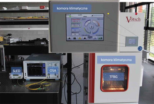
Figure shows the system for measuring the temperature at which TFBG structures were placed in the climate chamber. Measurement and interpretation signals from sensors using TFBG structures, enabling compensation of temperature changes during measurement.
It is known, that the position of polarization of the light input entered into the optical fiber, in which the TFBG structure is stored, exerts big influence at the fiber’s spectral specifications. Strong dependence on the light input polarization condition happens due to introducing the linearly polarized radiation into the fiber’s core in relation to the planes, forming the TFBG. Though the main resonance, i.e. Bragg peak is practically insensible to the light input polarization plane tilt, whereas in case of the claddings modes, there is observed the radiant transmittance visible change. Figure shows the light input polarization tilt influence at the characteristics of fiber transmission with recorded TFBG rating.
Measurements have been fulfilled using the TFBG with an angle = 7,5°. For analysis there has been selected the mode LP117, located in the cladding rig’s central part (Figure ). Transmittance characteristics of the mode thereof have been measured for the light input polarization corner angle α, changing from 0°, which has corresponded to S polarization type up to 90°, which, in turn, has conformed to P polarization type. Polarization plane tilt angle has changed with a step 5°, rotating a half of a plate, installed on the turning table, the motion of which has been controlled and set with an electronic controller. Outcomes of spectral measurements for the range of angles from 0 to 85° have been generalized on the Figure .
Figure 2. LP117 cladding module capacity changes for tilt angle various values of α input polarization plane in the range from 0° to 85°
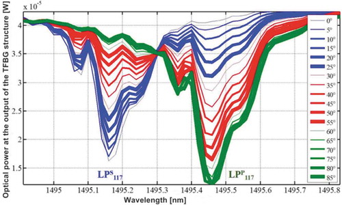
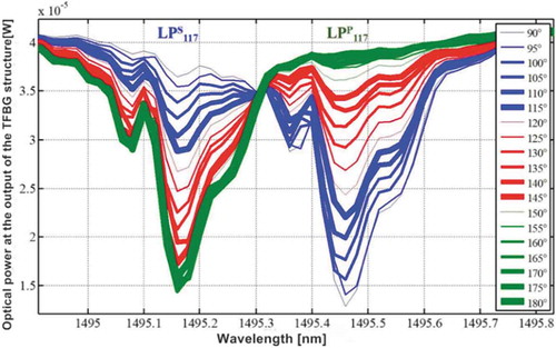
Figure 3. LP117 module capacity changes for various light input polarization tilt angle values in the range from 90° to 180°
Analysis of measurements outcomes, presented on the Figures and , shows the influence of the input polarization tilt angle change in the range from 0° to 90° at the amplitude monotonic change of the modes LPS117 and LPP117. Minimums magnitude of the spectral characteristics, corresponding to LPS117 mode, decreases, which happens in parallel to increasing the minimal height, corresponding to LPP117 mode. Therefore, LPP117 mode amplitude increases at the expense of LPS117 mode amplitude. It is connected with the fact, that along with the light polarization tilt angle change, the optical power is distributed between the modes of S-type and P. It is true for all claddings modes, as it is seen from the TFBG with tilt fiber transmittance characteristics, representing the wide spectral range on the Figure .
Figure 4. Numbering scheme of TFBG 7.5°, denoting the conditions S and P
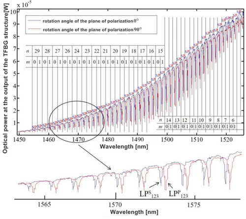
On the Figure the vertical lines denote spectral areas, corresponding to separate m azimuthal numbers and n radial. Above-mentioned capacity the «flow» between the cladding modes looks like absolutely different in case of the light input polarization plane tilt angle change from 90° to 180°, as it is shown on the Figure . For that light polarization changes range the angle raise increases to the minimal height, corresponding to LPS117 cladding mode, while LPP117 module amplitude decreases. Thus, if the polarization plane tilt angle exceeds 90° and increases further up to 180°, then in that range of its changes the capacity distribution returns into the state, which has happened under the angle 0°. It means, that the complete cycle of selected modes spectral characteristics changes constitutes 180° (Figure ).
Figure 5. Changes of mode capacity in the cladding LP122 for the α light input polarization plane tilt angle vary from 0° to 180°
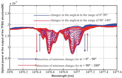
Figure presents amplitude changes of LP122 mode two parts, corresponding to polarities S and P. As, the α angle increases from 0° to 90°, the losses upon transmittance of LPPmn mode increase, which causes decrease of transmittance capacity, corresponding to the modes thereof, while the losses upon transmittance of LPSmn mode decrease, which in turn, increases the capacity of those modes.
Further increase of α angle in the range from 90° to 180° causes the losses decrease upon transmittance, corresponding to the mode LPPmn, evoking increase of their transmittance capacity, while the losses upon transmittance in the mode LPSmn increase, which in turn brings to decrease of capacity level of the transmission, corresponding to the modes thereof. Presented above spectral measurements outcomes, as well, the works on testing the TFBG sensors for controlling the polarization plane positions (Cięszczyk et al., Citation2018) have allowed developing the innovative method of measuring the signals from the rotation sensors, based on the TFBG usage. Apart from that, describing the interrogation method, having been presented in the chapter herein, shall be used within the context of other methods of this type, which having been elaborated nowadays.
Therefore, it should be noted, that the most widespread solution, allowing studying the simple and like Bragg gratings both in the refraction mode and transmittance one is the usage of other diffraction gratings, acting as filtering gratings (Wade et al., Citation2010). Measurements of light intensity from one FBG sensor depend on the light source capacity fluctuations. The solution for such problem might be the so-called optical power ratiometric measurements. They consist in measuring the optical power coefficient, for instance, having been obtained from two measuring channels. Consequently, the proportional interrogation methods, in principle, are resistant to output capacity changes of optical radiation source. The first attempts to use this method type have consisted in recording the signal, reflected by one FBG. Following modifications have included introduction of the FBG second filter into a track-control arm.
Methods of interrogating the signals from the sensors, based on optical diffraction gratings, using the two concurrent gratings allow attaining twice bigger measurements sensibility (Z. Zhang et al., Citation2012). That type measuring systems is also characterized by larger linearity of technological characteristics (Zhan et al., Citation2010) and possibility of compensating the temperature changes influence on the measurement result (Pei et al., Citation2008). In the work herein, we will present the interrogation method of modes claddings, coming from the sensors, based on the tilt Bragg structures. The method’s important advantage is in the fact, that all elements being used in it are passive. Therefore, it has all advantages, which are typical of the optic-fiber sensors. Block-diagram, demonstrating the method’s idea is shown on the Figure .
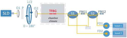
Figure 6. System for interrogating the signals from polarization sensors based on the TFBG structures
3. Results and discussions
The light from the superlight diode SLD (superluminescent diode) is sent via the system of polarization plane angle management to a transformer, which is the TFBG structure. Polarization plane position control system consists of two lens O1 and O2, polarizer P and half-wave plate λ/2. An optical signal, transmitted by the TFBG is sent to the like and simple Bragg grating FBG1, and afterwards, the reflected signal is sent via a brancher S1 to a photodetector FD2, an output of which is switched on to the optical power measuring unit. FBG1 gratings spectral characteristics are selected in the way to maintain their central wavelengths and half-widths correspond to the selected mode LPSmn of the TFBG structure, as it is shown on the Figure .
Figure 7. Mutual position of spectral characteristics of periodical structures from the system, shown on the Figure : (а) drop of polarization plane tilt angle, equals to 45°, (b) drop of polarization plane tilt angle, equals to 90°
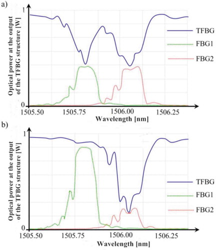
In its turn, an optical signal, transmitted by the system of consequently connected TFBG and FBG 1, is sent to the second direct grating: FBG 2, afterwards a part of the TFBG, which the FBG 2 adjusts to photodetector FD1 and optical power value are recorded using the capacity measuring unit. FBG 2 spectral characteristics are selected in such a way, that its central wavelength and half width conform to the selected mode LPPmn of the TFBG structure, as it is shown on the Figure . The polarization plane angle change of the light, introduced into the TFBG sensor, causes changing the transmittance of separate modes in gratings, which, in turn, leads to changing the amplitudes of the signals, reflected from FBG 1 and FBG 2 gratings. Therefore, it is possible to select definite modes P and S, in order to control a tilt angle not only of the polarization, but also of each element, which will force it to rotate.
It is also worth to denote, that FBG 1 and FBG 2 structures are used for reflecting the signals, corresponding to the modes P and S. Consequently, it is possible, that their reflecting features in the spectrum central part, close to the Bragg wavelength will not be flat. That specific feature might be observed, as well, on the example of the gratings, used in the system (Figure ). It is especially obvious in case of FBG 2 filter. Then there arises a question, whether the absence of flatness or convexity in the center section of optical filters spectral characteristics, consistent with the TFBG separate modes will not influence at measurements accuracy. The filters being used, shall have the features close to Bragg wavelength. It is attained, for instance, upon using the phase masks for recording the periodical structures with an adequate apodization, allowing getting the forms of FBG spectral characteristics, close to rectangular (Elzahaby et al., Citation2016).
Apart from that, in the presented interrogator system, there is no spectra shift but there is the intensity change of two TFBG modes types. Therefore, for instance, an intensity curve for every channel (FBG 1 and FBG 2) is proportionally shifted. Consequently, in the capacities ratios measuring system the effect of interrogating filters characteristics number does not influence negatively at the features of the sensor analysis. In the detection system, located closely, the most important information on the light input polarization plane tilt angle is contained in the capacity ratio, measured by photodetectors FD1 and FD2. At the instant herein it is worth to denote, that to secure high ratio of signal/noise, it is important, that the FBG 1 and FBG 2 gratings are strong (strong gratings), that is, they shall have high reflective ability value. Thus, such system saves from the necessity to use a spectrum optical analyzer. There is no need in recording an overall or even a selected part of the optical spectrum, which makes a measuring system simpler and cheaper. Moreover, the necessity in spectrometer measurements data processing is eliminated by means of their replacement with simple measurements of the signals from photodetectors. Thereby, the phenomenon of the power distribution between P- and S-modes in the TFBG structures is used due to the polarization angle change of the light, distributed via such structures. It allows using two conventional Bragg gratings as filters, adapted to a sensor and choosing selectively separate Bragg grating with tilt fiber modes, for instance, for measuring their optical power using the photodetectors Hereby we should mention, that as filtering elements there might be used the TFBG structures, as well (Li et al., Citation2011; Parker & De Sterke, Citation2000; Shahoei & Yao, Citation2013).
Temperature change causes the shift of overall TFBG, FBG 1, and FBG 2 spectral characteristics. If all gratings, processing and filtering, are stored at one optical fiber, their temperature sensibility will be equal. That peculiarity of the described system makes it insensible to the temperature. Its change will stimulate a spectral shift of all characteristics, while the power coefficient at photodetectors will remain as a constant value. Figure presents a chart, showing the powers ratio at photodetectors PFD1/PFD2 as the light input polarization plane tilt angle. Despite the system processing curve sinusoidal form, there might be selected such polarization angle range changes, for which a rotation angle via the system of the power ratio at photodetectors is close to linear. Rotation angle change from 0 ° to 90° causes decrease of power coefficient at photodetectors, while for polarization plane rotation angle drop in the range from 90° to 180°, the power factor increases and achieves the maximum for α angle, equal to 180° (Figure ).
Figure 8. Capacity, measured with a photodetector FD1, divided by the capacity, measured with a photodetector FD2, dependent on α light input polarization plane rotation angle
Usage of opposite changes of LPPmn and LPSmn modes amplitudes, that is, increase of losses for LPPmn mode transmittance with concurrent decrease of losses on transmitting the LPSmn mode type, conditioned with rotation of polarization plane, introduced into an optical fiber, secures big dynamics of signals changing.
Figure 9. Features of processing system from the Figure , both channels powers ratio in the α angle change range from 15° to 60°
The power ratio, reflected from FBG 1 and FBG 2, in the researched range of polarization angle change α =15°–60°, varies from 1.49 to 0.88. Consequently, the change in signals ratio in the system with two interrogator’s filters constitutes 59%, which is two times higher, than in case of interrogators with one optical filter. Dynamics of the power factor change at photodetectors in the presented system is higher, than in case of the system, based on one optical filter (Figure ).
Comparison of single and double-channel systems is possible if we analyze the signal level changes at different FBG 1 and FBG 2 filters, as it is shown on the Figure . Power change of the reflected light from separate FBG 1 and FBG 2 filters is lower, than in case of changing the power ratio at photodetectors in the scheme, shown on the Figure . If the TFBG sensor is filtered with only one filter (FBG1), then for angle measurements α = 15°−60° the normalized light power will change from 0.67 to 0.91 (Figure ), which gives 24% of the intensity change of the light, reflected from FBG1 filter. In turn, if a signal from the TFBG with a tilt fiber sensor has been filtered with one FBG 2 filter, then for the angle α =15°–60° the normalized light power will change from 0.98 to 0.78 (Figure ), which, in its turn, will result in the intensity power of the light, reflected from FBG1 filter, only 20%.
Figure 10. The intensity of the signal, reflected from FBG 1 and FBG 2 filters, has been measured in the scheme, shown on the Figure 6
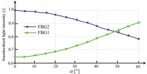
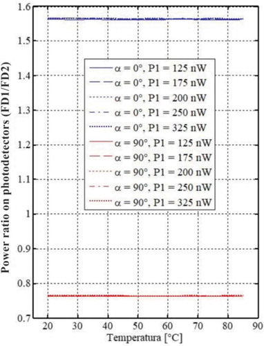
Figure 11. Power ratio at photodetectors as temperature function for two magnitudes of α light input polarization rotation angle and five power values (P1), recorded with a photodetector FD1
On the other hand, according to the outcomes, presented on the Figure , the power ratio, reflected from FBG 1 and FBG 2, in the researched range of polarization angle change α =15°–60°, varies form 1.49 to 0.88. Consequently, the change in signals ratio in the system with two interrogator’s filters constitutes 59%, which is two times higher, than in case of an interrogators with one optical filter.
Studying the temperature measurements outcomes, we can see some characteristics regularities, presented on the Figure . The most important from them relate to the method and overall measuring system insensibility to the temperature and intensity changes of the light radiation, incoming into the system. Firstly, upon the change of input light polarization from S type orientation (α =0°) to P-type orientation (α =90°) there is observed over twofold decrease of the power ratio, measured at both photodetectors. It is the only factor, which causes the power factor change and the temperature change in the range being measured, that is from 20 to 85°C, and poorly influences that factor value. Moreover, the optical power value, recorded with a photodetector FD1, which is the power function of the light, supplied for overall measured system, has a little influence at P1/P2 powers ratio.
Figure 12. Power factor at photodetectors as the temperature function for the running values of the power (P1), having been recorded with a photodetector FD1. Blue lines represent the measurements, fulfilled for S-type polarization, red lines correspond to the measurements, made with P-type polarization
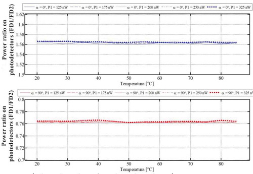
Figure shows the dependence of power ratio at photodetectors on temperature and power at the system’s input. Change of power factors values, measured by means of FD1 and FD2, is practically beyond measure, both in case of S-type light input polarization, and it is shown on the Figure . Figure shows the power ratio, measured with the photodetectors FD1 and FD2, depending on the temperature for several α angle values.
Figure 13. Power factor at photodetectors FD1/FD2 as the temperature function for several light input polarity plane rotation angle values
Moreover, the light polarization plane rotation angle does not change the power factors, measured with both photodetectors due to the temperature change. Though a factor value depends on the α angle value, for that parameter definite value the power factor P1/P2 is constant, despite the temperature changes, in which there is located a fiber-optic sensor with a stored TFBG structure.
Thus, it should be noted, that in the presented system there is observed insensibility to the temperature for various falling plane light polarization rotation angle values. That insensibility to the temperature also takes place for various intensity values of an optical signal, input into the measuring system. Therefore, the system is insensible to the temperature and fluctuations of the input light source power.
Temperature significantly affects the characteristics of optical structures showing periodicity along the optical fiber, on which they are produced. A change in temperature causes changes in the refractive index and also affects the size of the structure due to thermal expansion. The latter effect is dominant in the case of periodic structures, also TFBG. Measurements of many physical quantities require compensation or at least control of temperature changes. There are solutions, in which the authors claim, that TFBG sensitivity to temperature, approximately equals to FBG sensitivity and amounting to about 10 pm/°C is negligible, e.g., when measuring tilt angle, but in most applications such a change in length wave causes serious difficulties in the detection of other quantities, measured with such a sensor.
When using TFBG as liquid level sensors, appearing temperature changes are the main factor, negatively influencing the measurement. Monitoring the temperature changes is then possible by measuring the spectral shift of the Bragg main resonance, because it is insensitive to changes in the refractive index and, consequently, to the change in the level of the liquid, into which the TFBG element is immersed. There also known the constructions of fiber lasers for simultaneous measurement of liquid level and temperature. The interferometer consists of two constrictions, made on a single-mode fiber. In this arrangement, the interferometer and the usual homogeneous Bragg grid act as filters in the laser cavity. The system generates a signal with two wavelengths, with each signal component having a different temperature sensitivity. Systems are also used, in which the coreless fiber is combined with the usual, homogeneous FBG grating, obtaining dynamic temperature compensation.
Tracking the wavelength, corresponding to Bragg resonance is therefore the main method for measuring temperature in systems, using Bragg gratings as measuring heads. By tracking λB it is possible to monitor constantly the temperature of the sensor and, if necessary, compensate for the induced change in wavelength, e.g., at pH measurements. Generally speaking, it can be said, that if the signal from the TFBG structure is filtered by other periodic structures, e.g., FBG, then such filtered signal is already temperature-compensated. TFBG thermal sensitivity is manifested by a shift in the entire spectrum towards shorter or longer waves, as in the case of FBG. In practice, if the TFBG sensor and Bragg filters are written on the same optical fiber, their temperature sensitivity will be the same due to the same thermal expansion. The same shift of the spectral characteristics of TFBG and the optical filter means, that the optical power, transmitted by TFBG and filtered by FBG does not depend on temperature. This property causes the described method to be insensitive to temperature, if the sensor and filters work in the same environmental conditions (Kisała & Cięszczyk, Citation2015).
4. Conclusion
The paper herein presents the potentials for upgrading the parameters of light polarity analysis entry systems using the TFBG structures. There has been the possibility of using the conventional simple Bragg gratings for constructing an optical interrogator, operating in ratio metric mode. Though that method is similar to the consistent filters method there is a difference, that in the presented system the information about the value being measured is coded not in the wavelength shift, but in the changes of the TFBG cladding selected modes transmittance factor.
An important practical aspect of the system thereof is insensibility to the light source power fluctuations. Apart from that, the temperature insensibility of the TFBG transformer, FBG 1 and FBG 2 optical filters, stored at one optical fiber, single mode, is similar and constitutes approximately 10 pm/°С. It means, if all optical elements are located under one and the same outside temperature, their characteristics spectral shift will be equal, which supposes the possibility of carrying out the measurements of falling polarization plane rotation angle, insensible to the temperature changes.
Additional information
Funding
Notes on contributors
Kozbakova Ainur
Aliya Kalizhanova Candidate of physical and mathematical sciences, associate professor, the deputy general director of the Institute of Information and Computational Technologies of the Ministry of Education and Science CS of the Republic of Kazakhstan. Scientific interests of the leader: mathematical modeling of systems, models of transport systems network analysis, optimization methods, technologies for developing sensor systems for signals receive-transmit, mathematical modeling of Bragg fiber gratings.
Aliya Kalizhanova is the project manager #AP05132778. This work is supported by grant from the Ministry of Education and Science of the Republic of Kazakhstan within the framework of the Project #AP05132778 «Research and development of signals interrogation system with optical fiber refractometer, using the telecommunication networks» Institute of Information and Computational Technologies CS MES RK. Experimental researches have been carried out in the laboratories of optoelectronics at the Electric engineering and computer sciences faculty of Lublin Technical University.
References
- Cięszczyk, S., Harasim, D., & Kisała, P. (2018). Novel twist measurement method based on TFBG and fully optical ratiometric interrogation. Sensors and Actuators, A 272, 18–13. https://www.deepdyve.com/lp/elsevier/novel-twist-measurement-method-based-on-tfbg-and-fully-optical-lROqUTGpxL
- Cui, J., Hu, Y., Feng, K., Li, J., & Tan, J. (2015). FBG interrogation method with high resolution and response speed based on a reflective-matched FBG scheme. Sensors, 15(7), 16517–16535. https://doi.org/10.3390/s150716516
- Dong, B., Zhao, Q., Zhao, L., Jin, L., Miao, Y., Liao, T., & Zeng, X. (2008). Simultaneous measurement of temperature and force based on a special strain-function-chirped FBG. Sensors and Actuators, A 147(1), 169–172. https://doi.org/10.1016/j.sna.2008.05.019
- Elzahaby, E. A., Kandas, I. L., & Aly, M. H. (2016). Efficient apodized-TFBG for DWDM systems. In 2016 Sixth International Conference on Digital Information Processing and Communications (ICDIPC) (pp. 198–202). https://doi.org/10.1109/ICDIPC.2016.7470818.
- Kisała, P., & Cięszczyk, S. (2015). Method of simultaneous measurement of two direction force and temperature using FBG sensor head. Applied Optics, 54(10), 2677–2687. https://doi.org/10.1364/AO.54.002677
- Kisała, P., Wójcik, W., Kalizhanova, A. U., Kozbakova, A. K., Amirgaliyeva, Z. Y., Kashaganova, G., & Amirgaliyeva, S. N. (2019). Spectral properties of tilted Bragg gratings with different tilt angles and variable surrounding conditions. Przeglad Elektrotechniczny, 95(4), 185–188. http://pe.org.pl/abstract_pl.php?nid=11576
- Li, M., Shao, L.-Y., Albert, J., & Yao, J. (2011). Tilted fiber Bragg grating for chirped microwave waveform generation. IEEE Photonics Technology Letters, 23(5), 314–316. https://doi.org/10.1109/LPT.2010.2102013
- Lu, C., Cui, J., & Cui, Y. (2008). Reflection spectra of fiber Bragg gratings with random fluctuations. Optical Fiber Technology, 14(2), 97–101. https://doi.org/10.1016/j.yofte.2007.09.007
- Parker, R., & De Sterke, C. M. (2000). Reduced cladding mode losses in tilted gratings that are rotationally symmetric. Journal of Lightwave Technology, 18(12), 2133–2138. https://doi.org/10.1109/50.908824
- Pei, J., Yang, X., Zhan, Y., Zhu, R., & Xiang, S. (2008). On a fiber grating sensor system with the capacity of cross-sensitivity discrimination. Optik, 119(12), 565–570. https://doi.org/10.1016/j.ijleo.2007.04.001
- Pisco, M., Ricciardi, A., Campopiano, S., Caucheteur, C., Mégret, P., & Cusano, A. (2009). Time delay measurements as promising technique for tilted fiber Bragg grating sensors interrogation. IEEE Photonics Technology Letters, 21(23), 1752–1754. https://doi.org/10.1109/LPT.2009.2032780
- Shahoei, H., & Yao, J. (2013). Slow and fast light effects in a tilted fiber Bragg grating and the application in a continuously tunable microwave photonic filter. In IEEE MTT-S International Microwave Symposium Digest (MTT), 1-3 (2013). https://doi.org/10.1109/MWSYM.2013.6697682
- Silva, R. M., Ferreira, M. S., & Frazão, O. (2012). Temperature independent torsion sensor using a high-birefringent Sagnac loop interferometer. Optics Communications, 285(6), 1167–1170. https://doi.org/10.1016/j.optcom.2011.11.119
- Wade, S. A., Attard, D. P., & Stoddart, P. R. (2010). Analysis of transmission mode of a matched fiber Bragg grating interrogation scheme. Applied Optics, 49(24), 4498–4505. https://doi.org/10.1364/AO.49.004498
- Wang, Q., Farrell, G., & Freir, T. (2005). Study of transmission response of edge filters employed in wavelength measurements. Applied Optics, 44(36), 7789–7792. https://doi.org/10.1364/AO.44.007789
- Zhan, Y., Yu, M., Pei, J., Yang, X., & Xiang, S. (2010). A linearity interrogation technique with enlarged dynamic range for fiber Bragg grating sensing. Optics Communications, 283(18), 3428–3433. https://doi.org/10.1016/j.optcom.2010.04.095
- Zhang, M., Zhong, X., Zheng, W., Ruan, S., Dua, B., Yan, P., Liang, H., Liu, C., Li, L., & Su, H. (2019). Widely tunable, high optical signal-to-noise ratio erbium-doped photonic crystal fiber laser suitable for acetylene sensing. Optics and Laser Technology, 109, 525–533. https://doi.org/10.1016/j.optlastec.2018.07.035
- Zhang, Z., Yan, L., Pan, W., Luo, B., Wang, P., Guo, L., & Zhou, W. (2012). Sensitivity enhancement of strain sensing utilizing a differential pair of fiber Bragg gratings. Sensors, 12, 3892–3900. https://doi.org/10.3390/s120403891
- Zu, P., Chan, C. H., Jin, Y., Gong, T., Zhang, Y., Li, H., & Dong, X. (2011). A temperature-insensitive twist sensor by using low- birefringence photonic-crystal-fiber-based sagnac interferometer. IEEE Photonics Technology Letters, 23(13), 920–922. https://doi.org/10.1109/LPT.2011.2143400