
 ?Mathematical formulae have been encoded as MathML and are displayed in this HTML version using MathJax in order to improve their display. Uncheck the box to turn MathJax off. This feature requires Javascript. Click on a formula to zoom.
Abstract
Dynamic behavior of vehicle systems and driving comfort is an optimization problem. Passive suspension system usage in design considerations is seen in heavy commercial vehicles where the owners are known to be highly cost conscious. Subjective evaluation of driving comfort by skilled drivers results from individual’s perceptions about vibrations with wide variations. Simulation methods and/or objective test measurements are used for finding the influence of vehicle structural parameters and operational parameters. Studies were conducted with objective of finding the minimum acceleration levels at driver seat for optimum driving comfort. In such research, full-vehicle model optimization needs complex simulations and iterations of the approximations to achieve optimum ride comfort. In this paper, cost-effective optimization of the suspension system design and geometry for a new vehicle application are explained. Structural design variables selected through simulation models have been evaluated with objective of achieving minimum acceleration at the driver seat. Orthogonal array method was applied for reducing the number of test configurations to six, from 48 possible combinations. The results obtained show the structural design parameter optimization by objective evaluation as effective for optimum ride comfort. Acceleration levels measured in test vehicle configuration with the shortest kingpin mounting location and progressive stiffness springs with damper at the rear-axle showed a significant improvement in ride comfort. No significant improvement was observed from different damper configurations in the front suspension. Thus, the ride comfort was enhanced with minimal changes only in the rear-axle suspension design parameters and optimization of vehicle hitching point geometry during the development of new vehicle application. It has been proposed to select variables through simulation, optimize the number of test configurations using orthogonal array and make an objective evaluation of the ride impact progressively based on successive test results.
PUBLIC INTEREST STATEMENT
Developing an automobile vehicle for any application involves design optimisation of the components and systems. Driving comfort is the most important safety aspect of any long-haul vehicles. Any discomfort induces fatigue. Multiple components and systems affect ride comfort due to vibrations during traversing on unsmooth road profile. While development of active systems helps in controlling a component’s behaviour in any driving situations, it needs further maturity in terms of energy consumption by the onboard computing and control devices. Hence, cost-effective passive systems are still considered for heavy-duty commercial vehicles. As there are many influential parameters to be tuned, it is considered as an optimisation problem. Extensive simulations reduce the number of variables. However, the limit value of these variables needs to be physically evaluated. Objective measurement helps in deciding the options with less ambiguity. There are several means to optimise. Cost-effective method is orthogonal array and progressive evaluation to reduce number tests.
1. Introduction
Structural parameters are generally optimized through use of analytical or numerical (mathematical programming) methods, with respect to different failure modes under varying loading conditions (Kirsch, Citation1993). Finite-element (FE) computer analysis was used in the optimization of the design variables such as dimension, cross-section geometry, and structural topology, to ensure withstanding of in-service operating conditions without any failure.
Dynamic behavior of vehicles was also considered as an optimization problem (Van Asperen & Besselink, Citation1994). The dynamic response of the vehicle in terms of horizontal and vertical vibration and pitching moment was evaluated by computer simulations, using different operating parameters, laden and unladen conditions, smooth and rough roads (Dokainish & Elmadany, Citation1980). Early mathematical models were used for the prediction of the vibration responses to the road profile at tire contact points with different degree of freedom (DOF) used in modelling and ride comfort characterized through indices (Elmadany et al., Citation1979).
A recent computer model with nine DOFs of a heavy-duty tractor–trailer with passive suspension systems was used for simulating vehicle speed and load conditions on various road profiles and evaluation of ride comfort with a rigidly mounted driver cabin (Velmurugan et al., Citation2014). Dependency of resonance amplitude on vehicle speed in the longitudinal direction and vertical direction was predicted when tires traversed large obstacles using the FE model of a tire simulating structural and material properties (Wei & Olatunbosun, Citation2014). In the mathematical models, the track profile signal from unsprung component was used as input and the contribution of tire vibration was readily included as input signal, to avoid complex non-linear tire stiffness modeling (Corte et al., Citation2011).
A study of the optimization of different structural parameter in a MATLAB simulation was made using a rigid-elastic model (Ibrahim & El-Maddah, Citation1996) of heavy-duty trucks. Multi-level approximation techniques experimented for solving complex road response problems in a vehicle structure to ensure achievement of optimum ride characteristics, by coupling sub-optimization problems of axle, cabin and engine suspension sizes and the iterative optimization of geometry (Markine et al., Citation1996). The computer simulations were considered with all design variables and constraints such as (i) displacements of axle and cabin suspensions and the engine mounts, (ii) maximum dynamic wheel load, and (iii) acceleration of cargo. The influence of cabin suspension design and front suspension parameters evaluated in the virtual model were based on ADAMS, for locating the causes for subjectively felt abnormal vibration (Xu et al., Citation2016). A general numerical model was used for finding the equilibrium configuration derived based on kinetic and static analysis of road vehicle’s axle suspension elements (Alexandru, Citation2018).
A combined study of both the operational and the structural parameters has been seen in recent research works. Operating conditions such as a higher driving speed, poor road profiles, and unladen condition found to decrease ride comfort, while structural parameters such as spring stiffness and body stiffness exhibited complex response in variables observed (Jie et al., Citation2016). Tire stiffness and suspension damping factors having a positive influence in ride comfort were reported.
Subjective evaluation by humans requires statistically unbiased samples to overcome problems of variations in human perceptions regarding vibration and individual’s tolerance level. One such study (Velmurugan et al., Citation2012) considers vibration analysis as part of the ergonomics design of a heavy-duty truck cabin. The effect of variations on simple rubber coupling thickness has been reported in an experimental analysis of the front and rear primary suspensions, front and rear cabin coupling using an empirical tuning procedure (Corte et al., Citation2011).
The objective of this study is to evaluate the need to optimize structural parameters including geometrical dimensions, to achieve optimum ride comfort after a change in chassis design to suit vehicle application. Although researchers have reported optimizing front chassis suspension and cabin-suspension parameters through simulations and experimental analysis, optimum ride comfort often achieved in the trial and error method under subjective evaluations or by varying all possible design factors is rather sophisticated. This work focuses on the evaluation of the most cost-effective design by optimizing the influence of rear suspension design and trailer coupling geometry of a tractor–trailer vehicle application with the use of a passive suspension design, using combination of simulation and optimization methods.
2. Materials and method
As mentioned in the previous section, many research works in automobile domain relate to continuous optimization of various vehicle structural parameters and operating parameters meant for the improvement of ride comfort, either by using theoretical simulations, approximations itself or together with the practical objective evaluation methods of passive systems and active systems.
Theoretical developments of different control schemes in an active system for isolation of induced vibration involve one or two DOF to seven DOF, in either quarter, half or full vehicle model. Control strategies such as Skyhook damper, Robust valve design, Linear-Quadratic-Gaussian/Regulator, Kalman filter (estimator), Pole assignment, Neural network and Fuzzy logic have been used in active systems (Graf et al., Citation2009; Kaldas et al., Citation2012; Mantaras & Luque, Citation2006). Other ongoing research works relate to energy consumption and complexity optimization of active systems.
2.1. Test vehicle configuration
A tractor–trailer test vehicle with GCW (gross combination weight) limit of 49,000 kg was coupled with three-axle trailer, schematically shown in Figure . The tractor front-axle weight was 6,000 kg and in rear 19,000 kg. 11×20 tires were used for testing. During this evaluation, the front-axle suspension considered was of the four-leaf parabolic type spring for its lower friction between springs leaves (Gillespie, Citation1992) and a shock absorber at the axle. Elastomer mountings at the cabin front and dampers at the cabin rear were considered. This type of cabin suspension arrangement has proved to be effective in reducing vibration levels (Soliman, Citation2008; Soliman & Kaldas, Citation2011).
Figure 1. Schematic of Tractor-trailer vehicle
2.2. Control variables
A right combination of passive suspension parameters such as lower tire stiffness, axle suspension’s stiffness and damping coefficient optimization provides similar ride comfort of an active suspension system with higher tire stiffness (Soliman et al., Citation2014). As this study focuses on design optimization of structural parameters of classical truck with passive suspension system, there exists a need to evaluate the acquiescence of suspension parameters decided at the detailed design stage and that of geometric dimensions decided at the layout stage as found in previous studies (Suh & Yoon, Citation2018). Hence, the current design optimization work on the existing rigid truck for new tractor–trailer application necessitates the investigation of structural parameters such as rear-axle suspension’s spring stiffness along with the usage of right damper characteristics and kingpin geometrical dimensions. Four variables recommended were finalized from simulation, two additional test combinations were arrived at based on literature review and progressive evaluation of damper parameter was done (Table ).
Table 2. Arrangement of test parameters in L8 orthogonal array
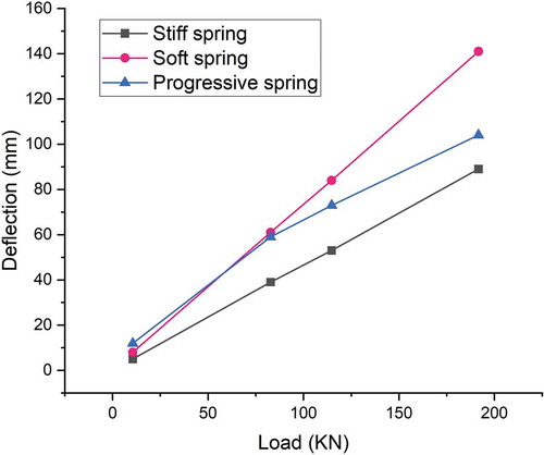
HIS (hydraulically interconnected suspension) system investigated for practical applications of racing and passenger cars in the past (N. Zhang et al., Citation2010) are not popular in production. Rear-axle suspension of heavy-duty truck is meant to have passive interconnection of two wheels on a single axle through an anti-roll bar. The other interconnection is between two rear axles together with inverted leaf spring assembly on either side. Inverted leaf spring stiffness is one of the influencing parameters in driving comfort (Soliman et al., Citation2001). In a multi-body computer simulation of a tractor–trailer vehicle with different loading conditions, the empty trailer produces increased acceleration levels that reduce with reduction in spring stiffness while maintaining the same deflection as that of the laden condition (Ibrahim et al., Citation2004). This emphasizes the need for varying the rear-axle spring stiffness depending on the service load conditions. Hence, the variable stiffness springs were evaluated against the standard configuration of uniform stiffness springs in this study (Figure ). Both springs were successively evaluated with and without dampers as part of the optimization process. GA logic applied on damper evaluation to combine with degrees of spring stiffness as the optimization of damper working best with the optimization of the spring characteristics.
Figure 2. Spring stiffness
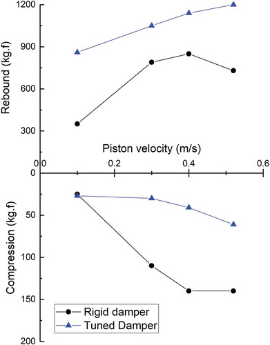
In active suspension dampers, permanent magnet characteristics and flute profile along with increase in end thickness were used for overcoming the disadvantages such as low level of thrust and regenerative efficiency and high force ripple (Peng & Zheng, Citation2016). However, in the passive system, the damping force varies according to the piston velocity in both the compression and the rebound directions optimized in the ride-works which have advantages such as tuning the damper for making the best use of the damper valve design and gives matching curves. Adjustment of the orifice diameter provided variations in the damping force for a given stroke length, which was limited by the mounting height. The requirement of damper at rear-axle suspension and variations in front-axle damping force have been considered for evaluation in this study (Figure ).
Figure 3. Damper Characteristics
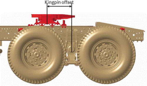
Fifth wheel coupling is used for connecting the truck with trailer with a kingpin that has an offset mounting distance from rear axles center as shown in Figure . The minimum side of kingpin offset is limited due to the regulation limits of the overall length of tractor–trailer combination for a given tractor wheelbase and the standard trailer length (Wei & Olatunbosun, Citation2014) and the maximum offset limited by load transfers to the front axle. The load from trailer to the tractor rear-axles is transmitted through the kingpin and the kingpin-offset creates load undulation and creates a pitching moment about the center axis between the rear axles, which could create a ripple effect through the chassis beam to the frontal structures and cabin mounts. Hence, the impact of the different kingpin offset [reduction up to 150 mm from legal limit on overall vehicle dimension] is evaluated in this study.
Figure 4. Kingpin Offset geometry
As per Indian Central Motor Vehicle Regulations, the RAW (rear-axle weight) of the tractor with two rear-axles is 19,000 kg, for trailer applications. Position of the trailer nose up and down have an influence on the load equalization of the rear-axles (Simmons & Mitchell, Citation1989). There is the possibility of payload parametric variations in trailer loads, that could also induce changes in vehicle inertia and geometrical parameters, which, in turn, affect vehicle dynamics (Huang & Wang, Citation2011). Hence, as part of the optimization, variations in rear-axles’ sprung mass [due to payload variations] have been considered for evaluation for any impact in driving comfort. A test vehicle loaded with concrete blocks weighing is as close as the test conditions as possible.
2.3. Simulation method
Ride comfort of an automotive seat system evaluated using FE analysis (Ramalingam & Jebaseelan, Citation2019). In a sophisticated simulation of 3D finite model of full truck-trailer combination, excitation of eight wheels corresponds to 2000 DOFs and hence multiple simulation packages including proprietary software was used for obtaining a ride index.
Present study deals with the evaluation of the effect of variables recommended for optimization by a similar FE computer simulations to improve ride comfort. The FE model of heavy-duty truck-trailer (Figure ) meshed and solved using MEDINA & PERMAS (proprietary software). The FE model excited using boundary condition inputs at truck-trailer tires contact point using measurements from RLDA (Road Load Data Acquisition) to simulate road undulations. The acceleration at driver seat taken as ride comfort response to the road undulations in this FE simulation. Independent design variables such as kingpin offset, rear damper requirement, rear spring ratings and front damper size were considered in the FE analysis. The values of the different levels of each parameter arrived at from FE simulations based on comparative improvement in ride comfort with reference to base design reference value. Starting at maximum offset in fifth wheel kingpin mounting as base for evaluation of ride comfort improvement over three different offset dimensions shown result of 13% improvement over base dimension. Tuning of damping force in front-axle shock absorber and introduction of a tuned rear-axle shock absorber were predicted to give 6%–11% improvement compared to base damper design. 12% improvement in vertical acceleration predicted from reduction of rear spring stiffness. These changes for a 42% improvement in vertical direction with more than 3% cost addition in suspension system and significant part development lead-time were recommended from the FE simulation. The estimated cost impact for the recommended variables is shown in Table . Hence, it is imperative to verify the simulation recommendations through objective measurements to achieve optimum ride comfort. The validation cost for an objective evaluation of these recommended parameters was reduced using DOE optimization technique and progressive evaluation method.
Table 1. Simulation results
2.4. Optimization method
Structural optimization of a bus structure was carried out using the GA (genetic algorithm) implemented in MATLAB. A sensitivity analysis of the variables on the objective results is important before carrying out the optimization (Gauchia et al., Citation2010). The advantage of GAs in obtaining good solutions and combining them in order to obtain even better solutions. An innovative design optimization strategy for solving automotive problems proposed involves a combination of results from the nonlinear FEA analysis, multi-body dynamics and a progressive meta-model based design (M. S. Kim et al., Citation2014). Such a progressive evaluation has been considered in this study for damper and spring stiffness combinations meant to reduce test cost and time. DOE (design of experiment) is necessary in optimizing variations for the objective function and examination of the effects on the design. Latin Hypercube and Orthogonal Array are the representative DOE methods (Dohi & Maruyama, Citation1990; Park et al., Citation2015; Y. Zhang et al., Citation2008). Partial fraction experiment for ride tuning was conducted using the optimization technique based on full factorial DOE and the process parameters prioritized using Taguchi’s orthogonal array:
where n is the number of independent variables and L is the number of levels in respective independent variable.
A total 48 configurations are possible with a combination of design variables considered and their variation levels. Hence, the test parameters are arranged in an orthogonal array as shown in Table to optimize a number of evaluations. As per Taguchi method (EquationEquation (1)(1)
(1) ), the minimum test configurations required to be evaluated in this experiment to understand the effect of variables is six.
2.5. Evaluation method
Practical evaluation has two approaches namely, subjective evaluation and objective evaluation. Human comfort determination done by subjective evaluation involves psychological and physiological sensitivity assessment. Assessment of driving stress involves a statistically significant number of human subjects and measurement of physiological data using an electroencephalogram (EEG) and eye-gazing (S. Kim et al., Citation2018). Repeatability, scalability and comparability are the key advantages of objective type evaluations (Little et al., Citation1999) compared with subjective evaluation. In the objective evaluation, the ride comfort is defined as a physical quantity and its description relates to the r.m.s (root mean square) of acceleration. A systematic evaluation of ride comfort using tri-axial accelerometers has been presented by Karanth and Raju (Citation2001). Hence, the objective evaluation of a ride comfort involves measurement of the acceleration and comparing it with whole-body vibration exposure limits as per the standard for seated people (ISO/AWI Citation2631-1, 1997/Amd 1:2010).
Objective evaluation using accelerometers in vertical and fore/aft directions carried out (SAE:J-Citation1490, 2011) details a uniform methodology for the measurement of ride vibrations. In a correlation exercise between the subjective ratings and the objective measurement, comfort sensitivity at the driver’s hip location, ischial tuberosities, had the highest correlation (M.S. Kim et al., Citation2011). Hence, the accelerometer was placed at the driver seat for the evaluation of ride comfort. Optimization goal was aimed at minimizing the vibration level at the driver seat. Vibration at the driver seat were measured using PCB make Triaxial ICP® seat pad accelerometer with a measurement range of ±10 g [98 m/s2 peak] and ±10% sensitivity . Multichannel data acquisition system was used for signal acquisition at the rate of 901 samples/s, since, as per the ISO 2631 standard, 300 samples/sec are required and ISO 8041:2005 recommends 9 times of the relevant central frequency to satisfy filter and weighting frequency characteristics, which is minimum 900 samples/sec.
The truck was tested on a high-speed test track at constant speed of 50 kmph, which is the nominal value between 40 and 60 kmph, the best possible fuel-economy speed-band of a heavy-duty truck in India. A study of vibrations in longitudinal, lateral and vertical directions was made by measuring the acceleration from three axes recorded for 240 s and converted from a time series to frequency series. The evaluation of the ride comfort focusing on peaks at transient events on time scale helps distinguishing between the absolute vibrations within the transient and the stationary segments of measured acceleration (Strandemar, Citation2005) mainly for shock-type vibrations. The current evaluation method focuses only on r.m.s values of acceleration signals after averaging out any transient events, due to the absence of any signal with a crest factor of nine and above, detected during the measurement. During this evaluation, no adverse change in the vehicle handling, or any swish noise or pattering sensitivity was expected and set as boundary condition for the ride comfort optimized design subjective evaluation.
In a previous study on sensitivity of shock-type vibration in a frequency range between 0.5 and 16 Hz, a significant discomfort was reported at frequencies lower than 0.63 Hz and resonation at 5.0 Hz and 6.3 Hz. The discomfort growth depends on frequency and has higher rate of growth at lower frequencies (AHN, Citation2010). Hence, there was a low-frequency vibration between 0 and 20 Hz focused in discussions, although measurements recorded were above this range. Human spinal resonance frequency was found to be 4–5 Hz of vertical vibration (Panjabi et al., Citation1986) and 10–12 Hz in the axial mode (Rasmussen, Citation1989). Recent research works show involvement in the modeling of biomechanical human body for evaluation instead of real human, showing the larger sensitivity of the human body as to vertical vibration with frequencies below 5 Hz (Shakhlavi et al., Citation2018). Hence, 2–4 and 10–12 are the reference frequency ranges set for this evaluation.
The measured acceleration values were averaged out and converted into frequency domains for the standard evaluation of different combinations of test variables. As shown in the L8 orthogonal table, combinations of variables were evaluated in a progressive manner according to the GA concept. For progressive evaluations, test combination-1 arrived from existing rigid vehicle and legal limit of 19,000 kg RAW were set as reference parameters. Summarized evaluation results are shown in Table for all further test combinations.
Table 3. Summary of results
3. Results and discussion
As the suspension parameters of front-axle and cabin, retained as combination-1 from the initial design were meant for rigid truck configuration with haulage application, the tuning of front-axle suspension damping force as per simulation recommendation was taken up as combination-2 and compared.
Rebound damping force at max piston velocity increased by 60% and compression stroke damping force reduced by 67% (Figure ). No significant improvement was found by the tuning of front-axle dampers in vertical vibration measured from the objective evaluation (Figure ) as against the prediction of 6% from simulation. This could be due to damping effect by the lubrication between the spring leaves which is generally discounted in the simulation model due to quantification difficulty. Based on the comparative evaluation results there is no possible improvement in ride comfort with increased damping force in front-axle suspension system. Progressive evaluations were continued with other optimization parameters (Figure ).
Figure 5. Effect of Front axle damper configuration optimisation
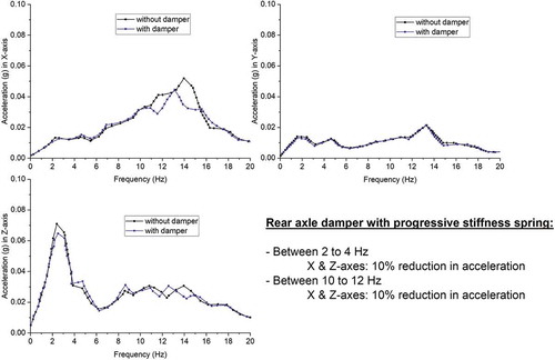
25% reduction in spring stiffness recommended from simulation for 12% reduction in vertical acceleration. According to previous studies, reduced stiffness results in reduced acceleration levels (Ibrahim et al., Citation2004) and sometimes, the unladen vehicle ride comfort is even sacrificed as the economic interest lies in travel with a fully loaded trailer (José et al., Citation2016). Attempt to improve ride comfort with reduced stiffness resulted in reduced ride height due to a larger spring deflection. A higher deflection was observed at low loads while improving ride comfort in unladen and part load conditions. Less spring deflection was allowed beyond 70% of rated load for meeting ride height and articulation requirements. Hence, a spring assembly with progressive stiffness range −35% to +10% of the existing constant rate higher stiffness spring was developed and tested for the verification of the simulation results. No improvement was seen in the vertical direction shown in the simulation; rather there was a 4%–6% negative impact in acceleration as shown in Figure . However, progressive stiffness springs reduced acceleration up to 25% in longitudinal and lateral directions (Table ).
Figure 6. Effect of Rear-axle damper and uniform stiffness spring
Rear damper addition alone in rear axle with the existing uniform rated high stiffness spring, combination-3 shows 10% improvement in X-axis and Z-axis at 2 and 3 Hz frequency range (Figure ), when compared to combination-2. Hence, addition of damper at rear-axle causes reduction in vibrations close to 10% as predicted in the simulation. However, a tuned damper alone can only make out the best of the given vehicle structures. While it cannot correct inherent vehicle flaws, it is possible to cover up certain flaws but at the cost of other attributes. For example, overdamping to cover-up mismatched springs could increase the harshness of the sprung end of the vehicle. Hence, the optimum damping characteristics were developed together with the establishment of optimum stiffness spring according to a given sprung mass. As discussed in earlier section, the damper was added to the optimized progressive stiffness spring setting to enable finalization of the structural parameters design (Figure ).
Figure 7. Effect of Rear-axle spring stiffness optimization
Figure 8. Effect of Rear-axle damper and progressive stiffness spring combination
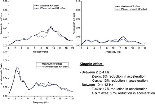
Lower kingpin offset reduces the acceleration level in all axes. The lowest possible kingpin offset reduced accelerations, 8% smaller in the objective evaluation than simulation results, particularly in the vertical direction at lower frequency range. 5% improvement in lateral acceleration and 13% improvement in longitudinal acceleration was found at lower frequency. However, at a higher frequency range of 10–12 Hz, a significant reduction of acceleration levels was observed. A reduction in X-axis and Y-axis acceleration was observed upto 27% and upto 17% reduction in Z-axis acceleration levels at a higher frequency range (Figure ), which is critical frequency for human spinal resonance. Hence, the fifth-wheel coupling location with respect to the center line of the rear axles contributes significantly. The load from the rear trailer is hooked on to this mounting location which generates pitching moment at the kingpin with respect to the rear-axles center point and thus rocks the vehicle from behind. From the simulation results and objective evaluation results it is proven that the shortest distance between fifth-wheel coupling point and rear-axle center line (kingpin offset) would give better ride comfort. However, there is a limit to reduce this offset as this reduction would lead to increase in overall vehicle length, which is a legally constrained limitation.
Figure 9. Effect of Kingpin offset geometry optimization
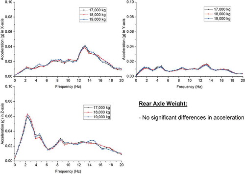
The FE simulation was carried out with the maximum RAW of 19,000 kg as per legal limit of twin rear-axle tractor vehicle. However, as seen in Section 2.1, some previous studies show the reduction in payload and dynamic weight transfers during trailer nose up, having influence on ride comfort & handling. Hence, the effect of RAW variation was also evaluated, keeping all operational and structural parameters constant. Variations were made in the RAW in two 1000 kg steps from 19,000 kg to understand the impact of a smaller RAW. A reduction in RAW showed upto 5% reduction in vibrations in horizontal and vertical planes (Figure ). This measurement was useful in understanding the influence of payload variations on ride comfort; however, practically the commercial vehicles operated closer to the maximum permitted load due to economy of operation.
Figure 10. Effect of Rear-axle weight
Although the usage of damper in rear has a significant influence in fore/aft accelerations, there was no impact due to variations in damper configurations in the front-axle. Hence, existing damper design retained for the front axle and the optimized damper considered for rear axle. The rear suspension spring with progressive stiffness rating helps improvement in fore/aft acceleration and lateral moments. Hence, a progressive stiffness spring together with a damper was chosen as the final rear-axle suspension configuration. In all directions a significant improvement in acceleration levels was found with the optimized location of the fifth wheel coupling mounting location, which was governed by the overall length and the wheelbase limits. A reduced kingpin offset improved vibration levels in all directions and hence the lowest value of offset was retained as the final geometrical configuration.
4. Conclusion
Various studies shows mathematical simulation attempts useful for prediction of design parameters for early prototypes. Objective ride evaluations are necessary for optimizing the simulation recommended structural size and geometrical parameters to achieve the best ride comfort of overall vehicle running on typical service roads. In this work, a cost-effect solution has been adopted in optimizing structural parameters of a heavy-duty rigid truck while designing for different application such as a tractor–trailer (Figure ).
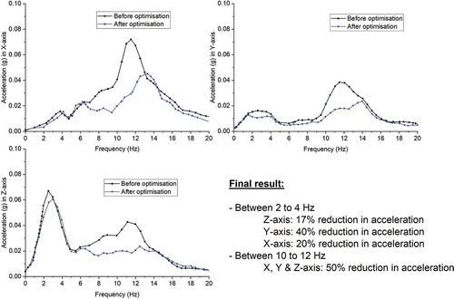
Table and Figure show a summary of ride comfort improvements observed with different vehicle structural parameters at two-reference frequency range. The overall reduction in vertical acceleration with optimized design parameters is 17%, while the FE simulation predicted about 40% at lower frequency range of 2–4 Hz. At frequency range of 10–12 Hz, 50% reduction achieved in all direction. This study showed the most influential vehicle parameter as the fifth wheel coupling mounting distance from the rear-axles’ center axis, which provided a significant improvement in longitudinal, lateral and vertical directions. Thus, the objective evaluation of structural and geometrical parameters was identified through simulation and optimization of the number tests using orthogonal array was found suitable for cost-effective optimization of passive suspension in commercial vehicles.
Figure 11. Result of optimized final configuration
Additional information
Funding
Notes on contributors
Kumaraswamidhas L.A.
Dr. L. A. KUMARASWAMIDHAS, He acquired his Ph.D degree from Anna University, Chennai, in 2008. Now he is working as an Associate Professor in the Department of Mining Machinery Engineering, Indian Institute of Technology (ISM), Dhanbad, India. As an active researcher, Dr.L.A.Kumaraswamidhas is an Editorial Board Member of 5 Reputed Journals and also a reviewer of 6 International journal. He has contributed to the areas of Automobiles, Vibration, Tribology, Engineering Design and Computational Fluid Dynamics with 98 research publications among which 30 are SCI Journals and 2 patents. A technical and education management expert, Dr.L.A.Kumaraswamidhas, believes that Science, Engineering and Technology are advancing at a fast pace and obsolescence of physical infrastructure, skills and competence takes place rapidly. Current article highlights the effective utilization of different research methods and suggests the best combinations of these methods for developing new automobile vehicles in a cost-effective way.
References
- AHN, S. J. (2010). Discomfort of vertical whole-body shock-yype vibration in the frequency range of 0.5 To 16 Hz. International Journal of Automotive Technology, 11(6), 909–17. https://doi.org/10.1007/s12239-010-0108-z
- Alexandru, C. (2018). Method for the Kinetostatic analysis of the road vehicles axle suspensions. Springer.
- Corte, E., Duarte, M. L. M., Batista, H. S., & Silva, G., 2011. Commercial vehicle comfort under human vibration perspective. SAE Technical Paper, pp. 2011-36-0269.
- Dohi, M., & Maruyama, Y. (1990). Ride comfort optimisation for commercial trucks. SAE Journal of Commercial Vehicles, 99(2), 890–902. https://www.jstor.org/stable/44469457
- Dokainish, M., & Elmadany, M. (1980). Random response of tractor-semitrailer system. Vehicle System Dynamics, 9(2), 87–112. https://doi.org/10.1080/00423118008968618
- Elmadany, M., Dokainish, M., & Allan, A. (1979). Ride dynamics of articulated vehicles - A literature survey. Vehicle System Dynamics, 8(4), 287–316. https://doi.org/10.1080/00423117908968609
- Gauchia, A., Diaz, V., Boada, M., & Boada, B. (2010). Torsional stiffness and weight optimisation of a real bus struture. International Journal of Automotive Technology, 11(1), 41–47. https://doi.org/10.1007/s12239-010-0006-4
- Gillespie, T. D. (1992). Fundamentals of vehicle dynamics. SAE International.
- Graf, C., Maas, J., & Pflug, H.-C. (2009). Concept for an active cabin suspension. IEEE.
- Huang, X., & Wang, J. (2011). Light weight vehicle control-oriented modeling and payload parameter sensitivity analysis. IEEE Transactions on Vehicular Technology, 60(5), 1999–2011. https://doi.org/10.1109/TVT.2011.2148135
- Ibrahim, I., & El-Maddah, M. (1996). Influence of frame flexibility and fifth wheel constraints on the ride behaviour of articulated semi-trailer systems. AMME.
- Ibrahim, I. M., Crolla, D. A., & Barton, D. C. (2004). The impact of the dynamic tractor-semitrailer interaction on the ride behaviour of fully-laden and unladen trucks. Journal of Commercial Vehicles, 113(2), 208–218. https://www.jstor.org/stable/44718814
- ISO/AWI 2631-1, 1997/Amd 1:2010. Mechanical vibration and shock — Evaluation of human exposure to whole-body vibration — Part 1: General requirements. ISO.
- Jie, L., Wenzhu, W., Xiong, G., & Zhenwei, A. Z., 2016. Study on the influence of different factors on heavy truck ride comfort. SAE Technical Paper, pp. 2016-01-0440.
- José, G. D. G., Rebelatto, M., Schwanke, R. G. L., & Strohaecker, T. R., 2016. Vibration frequencies and vertical acceleration levels assessment on a truck trailer chassis considering various types of pavement and load conditions. SAE Technical Paper 2016-36-0067.
- Kaldas, M. M., Soliman, A. M., Barton, D., & Brooks, P. C. (2012). Fuzzy-Skyhook control for active suspension systems applied to a full vehicle model. International Journal of Engineering and Technology Innovation, 2(2), 85–96. http://ojs.imeti.org/index.php/IJETI/article/view/83
- Karanth, N., & Raju, S., 2001. Comfort and durability of cabin of commercial vehicle. SAE Technical Paper 2001-26-0040.
- Kim, M. S., Kang, D. O., & Heo, S. J. (2014). Innovative design optimization strategy for the automotive industry. International Journal of Automotive Technology, 15(2), 291–301. https://doi.org/10.1007/s12239-014-0030-x
- Kim, M. S., Kim, K. W., & Yoo, W. S. (2011). Method to objectively evaluate subjective ratings of ride comfort. International Journal of Automotive Technology, 12(6), 831–837. https://doi.org/10.1007/s12239-011-0095-8
- Kim, S., Rhee, W., Choi, D., Jang, Y. J., & Yoon, Y. (2018). Characterizing driver stress using physiological and operation data from real-world electric vehicle driving experiment. International Journal of Automotive Technology, 19(5), 895–906. https://doi.org/10.1007/s12239-018-0086-0
- Kirsch, U. (1993). Structural optimization: Fundamentals and applications. Springer.
- Little, E., Handrickx, P., Mergay, M., & Deel, J., 1999. Ride comfort analysis: Practice an procedures. Symposium on International Automative Technology (SIAT’99).
- Mantaras, D. A., & Luque, P. (2006). Ride comfort performance of different active suspension systems. International Journal of Vehicle Design, 40(1/2/3), 106–125. https://doi.org/10.1504/IJVD.2006.008456
- Markine, V., Meijers, P., Meijaard, J., & Toropov, V. (1996). Optimization of the dynamic response of linear mechanical systems using a multipoint approximation technique. Springer.
- Panjabi, M. M., Andersson, G. B., Jorneus, L., Hult, E., & Mattsson, L. (1986). In vivo measurements of spinal column vibrations. The Journal of Bone and Joint Surgery, 68-A(5), 695–702. https://doi.org/10.2106/00004623-198668050-00009
- Park, J. H., Kim, K. J., Lee, J. W., & Yoon, J. K. (2015). Light-weight design of automotive suspension link based on design of experiment. International Journal of Automotive Technology, 16(1), 67–71. https://doi.org/10.1007/s12239-015-0007-4
- Peng, C., & Zheng, L. (2016). Design and optimization of Halbach active suspension actuator of vehicle. Springer.
- Ramalingam, M., & Jebaseelan, D. (2019). The effect of vibration characteristics of an automotive seating system on ride comfort – A finite element study. Proceedings of the Institution of Mechanical Engineers Part C Journal of Mechanical Engineering Science 1989-1996, 233(18), 6588–6601. https://doi.org/10.1177/0954406219858172
- Rasmussen, G., Ed. (1989). Human body vibration exposure and its measurement. The Journal of the Acoustical Society of America 73, 2229 (1983). https://doi.org/10.1121/1.389513
- SAE:J-1490. (2011) . Measurement and presentation of truck ride vibrations. SAE International.
- Shakhlavi, S. J., Marzbanrad, J., & Tavoosi, V. (2018). Various vehicle speeds and road profiles effects on transmitted accelerations analysis to human body segments using vehicle and biomechanical models. Cogent Engineering, 5(1), 1461529. https://doi.org/10.1080/23311916.2018.1461529
- Simmons, I., & Mitchell, C. (1989). The equalisation of truck bogie axle weights. Second International Symposium on Heavy Vehicle Weights and Dimensions.
- Soliman, A. (2008). Improvement of the truck ride comfort via cab suspension. SAE Technical Paper 2008-01-1148.
- Soliman, A., & Kaldas, M. (2011). Improvement of truck semi-trailer ride comfort using different control strategies. International Journal of Engineering Simulation, 12(2), 3–13. http://intjes.co.uk/vol12num2/papers/paper1_abstract.html
- Soliman, A. M. A., Abd Allah, S. A., El-Betar, A. A., & Hamed, M. S. (2001). Effect of suspension spring stiffness on the vehicle dynamics. Heavy Vehicle Systems, A Series of the International Journal of Vehicle Design, 8(3,4), 316–334. https://doi.org/10.1504/IJHVS.2001.001166
- Soliman, A. M. A., Gazaly, N. M., & Kadry, F. S., 2014. Parameters affecting truck ride comfort. SAE Technical Paper 2014-01-0147.
- Strandemar, K. (2005). On objective measures for ride comfort evaluation. Royal Institute of Technology (KTH).
- Suh, K., & Yoon, H. (2018). Design optimisation of a rear independent suspension for the Korean light tactical vehicle. International Journal of Automotive Technology, 19(2), 245–252. https://doi.org/10.1007/s12239-018-0023-2
- Van Asperen, F., & Besselink, I. (1994). Numerical optimization of the linear dynamic behaviour of commercial vehicles. Vehicle System Dynamics, 23(1), 53–70. https://doi.org/10.1080/00423119408969049
- Velmurugan, P., Kumaraswamidhas, L., & Sankaranarayanasamy, K. (2012). Measurement of whole‐body vibration exposure from unsuspended cabin tractor semi‐trailers. Human Factors and Ergonomics in Manufacturing & Service Industries, 22(6), 481–486. https://doi.org/10.1002/hfm.20285
- Velmurugan, P., Sankaranarayanasamy, K., Kumaraswamidhas, L., & Pazhanivel, K. (2014). Ride comfort analysis of unsuspended cabin tractor semi-trailer. International Journal of Vehicle Structures & Systems, 6(4), 104–109. http://dx.doi.org/10.4273/ijvss.6.4.04
- Wei, C., & Olatunbosun, O. A. (2014). Transient dynamic behaviour of finite element tire traversing obstacles with different heights. Journal of Terramechanics, 56, 1–16. https://doi.org/10.1016/j.jterra.2014.07.001
- Xu, X., Yan, F., Li, Y., Chen, W., & Cao, Y. (2016). Ride comfort simulation and abnormal vibration improvement of a commercial vehicle. Springer.
- Zhang, N., Smith, W. A., & Jeyakumaran, J. (2010). Hydraulically interconnected vehicle suspension: Background and modelling. Vehicle System Dynamics, 48(1), 17–40. https://doi.org/10.1080/00423110903243182
- Zhang, Y., Tang, C., Chen, W., Chen, L., & Yang, J. (2008). Robust optimal design for enhancing vehicle handling performance. SAE International Journal of Passenger Cars - Mechanical Systems, 1(1), 536–544. https://doi.org/10.4271/2008-01-0600