
 ?Mathematical formulae have been encoded as MathML and are displayed in this HTML version using MathJax in order to improve their display. Uncheck the box to turn MathJax off. This feature requires Javascript. Click on a formula to zoom.
Abstract
High-surface area carbon with porous structure can provide a large electrical-double layer as energy storage in supercapacitors. Herein, porous graphene-like materials with high-surface area were prepared from renewable coconut shell charcoal via KOH activation followed by oxidation in a harsh environment using a modified-Hummer method. Using the method, the surface area of the treated coconut shell charcoal increased significantly from about 189.97 m2/g to 642.45 m2/g with a pore diameter of approximately 5 nm. As expected, the increase in surface area increased the capacitance significantly, by up to 46-fold, from 3.22 to 148.20 F/g. These results demonstrated that the low cost renewable porous graphene-like material prepared from coconut shell charcoals is promising for use as electrode material for supercapacitor.
PUBLIC INTEREST STATEMENT
We have devised a cheap method to convert coconut shell charcoals into highly porous graphene-like materials. Graphene is a single, thin layer of graphite, the material used in pencil lead, that could be the future of technology. It is because graphene has unique properties such as flexible, transparent, highly conductive, and so on. Graphene or graphene-like can be used as the electrode materials for energy storage and conversion devices such as Li-ion battery and supercapacitors. The fast-growing market of the small portable electronics and hybrid electrical devices highly demand supply of storage system of electrochemical energy. Graphene-like materials derived from coconut shell charcoals could be an alternative to fulfill the demand supply, providing the abundantly available cheap waste renewable biomass resources and cheap method.
1. Introduction
Supercapacitors have attracted considerable attention due to their high-power density, long cycle life, and fast charging time that make them the promising power source in electronic equipment and hybrid electrical vehicles. The energy storage in supercapacitors can be in the form of electrical double-layer capacitors (EDLCs) or fast and reversible Faradaic reactions (pseudocapacitors). Carbon materials have been recommended as the most promising candidates for supercapacitors (Sun et al., Citation2013), and in the case of EDLCs, activated carbon has been the most widely used as the electrode material (Ghosh et al., Citation2019) (Zhao et al., Citation2011). Activated carbon is low cost because it can be prepared easily from abundantly available and low cost renewable natural resources such as biowastes, sawdust, coconut shell, bamboo, etc. A wide variety of renewable natural resources have been used to prepare carbon-based electrodes for supercapacitors including ginkgo leaves (Zhu et al., Citation2018), Rose (Zhao et al., Citation2018), wheat straw (Gou et al., Citation2020), and bamboo (Yang et al., Citation2014). The capacitance or storage performance of activated carbon-based supercapacitors is greatly dependent on the specific surface area of the active material and the charge accumulates at the electrode/electrolyte interface (Przygocki et al., Citation2018). The poor conductivity and a huge amount of micropores in activated carbons hinder the ion and electron transport, which in turn, deteriorate significantly the capacitance performance at high rates (Sun et al., Citation2013). To overcome the poor electrical conductivity of activated carbon, the activated carbon is generally graphitized. However, graphitization leads to reduce the specific surface area. Recently, hard carbons, a type of disordered carbon material and non-graphitizable, have gained much attention for use as electrode materials for EDLCs (Ghosh et al., Citation2019). Hard carbons can be produced by carbonization of various biomasses such as cellulose, coconut shell, charcoal, etc. Coconut shells, consisting mainly of cellulose fibers, are biomass waste which is abundantly available in Indonesia and widely distributed in the earth. They are typically used as raw material to produce charcoal by carbonization in a limited-oxygen environment for use as either domestic or industrial uses. Coconut shell charcoal is hard carbon and because of that it can be a potential candidate for conversion into electrode material used in supercapacitors.
In the present work, a modified-Hummer method with either pretreatment or post-treatment was used to prepare graphene-like material from coconut shell charcoal for use as electrode material in supercapacitor. The treatment was aimed to increase the surface area of the carbon material to enhance the capacitance capacity. The effect of the order of pretreatment and post-treatment on the properties of treated carbon and its capacitance was investigated.
2. Experimental
2.1. Materials
The coconut shell charcoal (CSC) were obtained from local market in Surabaya, Indonesia. The proximate composition analysis of the CSC is shown in Table . All chemicals used to prepare the graphene from the CSC were reagent grade and used without further purification. The sulfuric acid (H2SO4; 98.0%) and hydrogen peroxide (H2O2; 30%) were supplied by Merck. The sodium nitrate (NaNO3; 99.5%) was purchased from SAP Chemical. The potassium permanganate (KMnO4; 99.5%) and potassium hydroxide (KOH; 99.5%) were purchased from UNI-Chem, Indonesia.
Table 1. Proximate analysis of CSC
2.2. Synthesis
Prior to use, CSC was ground and sieved to a particle size of approximately 125 μm. The CSC particles were mixed with KOH solids and ground in an agate mortar. The weight ratio of CSC:KOH was 1:4. The CSC-KOH mixture was placed in a ceramic boat and introduced into an alumina tube of tubular furnace. Nitrogen (UHP) gas was flowing during the thermal treatment, which was carried out successively at 400°C for 1 h and 800°C for 3 h. The heater was turned off, and the sample was cooled naturally to room temperature, washed with successively 20 wt.% H2SO4 and deionized water, and dried in an oven at 80°C for 12 h. The dried sample, hereafter will be referred to as activated carbon (AC), was used as raw materials to produce graphene-like material.
2Graphene-like material was prepared using a modified Hummers approach (Vieira et al., Citation2016). Two grams of AC and 2 g of NaNO3 were put into 92 mL of 98.0% H2SO4 in a beaker glass placed in an ice bath and stirred by a magnetic stirrer. After 30 min, 10 g of KMnO4 was added and the temperature was increased to 40°C by putting the mixture in a water bath. After 40 min, 100 mL deionized water was added slowly (in an ice bath) to avoid a rapid temperature raise and it was allowed in the ice bath (~5°C) for 3 h. Then, it was heated to 35°C and kept at this temperature for 15 min. After that, 100 mL of demineralized water was added slowly, and the mixture was cooled down to ~5°C and kept at this temperature for 15 min. Fifteen milliliters of H2O2 was added slowly until no bubble could be observed anymore. The solids were separated from the mixture by a centrifuge, washed subsequently with HCl solution and deionized water and dried in an oven at 80°C. The sample was denoted as AC-H. For reference, CSC was directly treated with the same procedure as above and the sample was labeled as CSC-H.
To enhance further the surface properties, the AC-H was reduced by citric acid at high temperature using the procedure described as follows. The GO in the amount of 5 mg were dispersed in 20 mL of deionized water and its pH was adjusted to 9 by adding 1 M NH4OH aqueous solution. Then, 4 g of citric acid as reducing agent for the AC-H was added to the mixture. The mixture was heated in a tubular furnace at 950°C under flowing nitrogen gas for 120 min. After the heater was turned off, the solid sample cooled naturally to room temperature. The sample was denoted as AC-H-R.
2.3. Characterization
Crystal structures of graphene were identified by X-ray diffraction (XRD; PANalytical X’Pert Pro, The Netherlands) using Cu Kα radiations (λ = 1.54 Å). Infrared and Raman spectra were recorded using, respectively, a Fourier Transform Infrared (FTIR) spectrophotometer (IRTracer-100, Shimadzu, Japan) and a Raman Spectroscopy (XploraPlus, Olympus, Japan). The specific surface area was measured by multi-point nitrogen adsorption at its boiling point (Nova 1200, Quantachrome, US). The samples were degassed at 300°C under flowing nitrogen for 3 h prior to the measurements. The specific surface area was calculated by Brunauer–Emmet–Teller (BET) method. The pore volume was taken at the relative pressure approaching unity. The pore size was estimated by Barrett-Joyner-Halenda (BJH) method.
2.4. Electrochemical characterization
The electrochemical properties of the as-prepared graphene were tested as the electrode in supercapacitor by cyclic voltammetry (CV) using a conventional three-electrode system in a 1 M Na2S2O3 aqueous solution on a potensiostat/galvanostat instrument (Autolab PGSTAT 302 N, Metrohm). Platinum foil and Ag/AgCl 3 M KCl (0.21 V vs. SHE) were used as, respectively, the counter and reference electrodes. The working electrode was prepared by mixing the as-prepared graphene with poly(vinylidene difluoride) (PVdF; Sigma-Aldrich) binder with a weight ratio of 10:1 using N-methylpyrrolidone (NMP; Sigma-Aldrich) solvent to form a paste. The paste was casted to a nickel foam and dried in an oven at 60°C. The CV measurement was carried out by scanning the potential between –1.0 and 0 V (vs. Ag/AgCl) at a scan rate of 50 mV/s.
3. Results and discussion
3.1. Particle characteristics
Figure shows the XRD pattern of activated carbon obtained from coconut shell charcoal using the KOH activation as described above. The diffraction pattern shows two peaks at around 22.5° and 43° corresponding to disordered graphitic 002 and 100/101 planes, respectively (Pradhan & Sandle, Citation1999). This pattern differs from that of the coconut shell charcoal that has only one broadening peak at around 24°, indicating a non-crystalline carbon. The peaks appear in the diffraction pattern of activated carbon denote the interlayer spacing/the stacking high (Lc) and the microcrystallite diameter/the lateral size (La) (Girgis et al., Citation2007). Moreover, the disorder in carbon structure is probably caused by the random displacement between adjacent layers and local stacking faults produced during the pre-treatment process including grinding and thermal treatments (Babu & Seehra, Citation1996). Since grinding might have an effect on the disorder of carbon structure, the effect of particle size, i.e., grinding, was investigated.
Figure 1. XRD pattern of activated carbon obtained from coconut shell charcoal (AC)
A well-known Hummer method is the most common methods to prepare graphene by exfoliation of graphite. Since the structure of carbon in the activated carbon was disordered graphitic, a harsh oxidation using the modified-Hummer method might be used to treat the activated carbon to have properties like graphene. Figure shows the effect of particle size on the XRD patterns of AC treated with the modified-Hummer method (AC-H). As expected, the diffraction peaks appeared in the original activated carbon still exist after it was treated with the modified-Hummer method. The diffraction peak broadened when the initial particle size decreased (from 35 to 200 mesh). As mentioned above, grinding may influence the disorder structure of carbon. The smaller the size was, the more intense the grinding was. As a result, the carbon structure became more disorder as shown by the broader diffraction peaks, and in the case of 200 mesh the peak at 43° nearly disappears. The broader peak at 24° indicates the structure similar to the stacked structure of graphite oxide (Toh et al., Citation2014).
Figure 2. XRD pattern of the activated carbon samples of different sizes treated with the modified-Hummer method
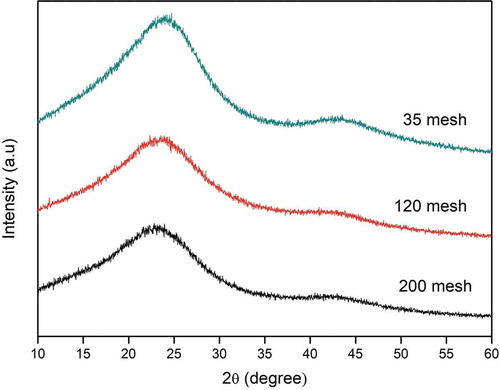
Figure shows the XRD patterns of the activated carbon treated with only the modified-Hummer method (AC-H) and the modified-Hummer method plus reduction using citric acid (AC-H-R). As discussed above, the XRD pattern of AC-H shows a broad peak at around 24° indicating the material has a stacked structure of graphite oxide. On the other hand, the peak was slightly shifted to 23.3° when the material was reduced with citric acid (AC-H-R), and the peak at 43° completely disappeared. The diffraction pattern is similar to that of the reduced graphene oxide (rGO) (De Silva et al., Citation2017). Thus, it seems that rGO can be prepared from activated carbon by subsequently treated it with the modified-Hummer method and citric acid reduction at high temperature.
Figure 3. XRD patterns of activated carbon treated with the modified-Hummer method (AC-H) and the modified-Hummer method plus reduction using citric acid (AC-H-R)
Figure presents the Raman spectra of the activated carbon treated with: (a) the modified-Hummer method (AC-H) and (b) the modified-Hummer method plus reduction using citric acid (AC-H-R). There are three peaks in the Raman spectra of the two samples which are at around 1362 cm–1 (D band), 1569 cm–1 (G band), and 2743 cm–1 (2D band). The peaks can be attributed to graphitic structure of RGO (Sun et al., Citation2013). The D-band indicates the presence of defects in the graphitic materials due to bond-angle disorder, bond-length disorder, vacancies edge defects, etc. On the other hand, G-band is related to the stretching motion of the pairs of carbon sp2 atoms while the broad peak in 2D-band indicates the number of layers formed (Dubale et al., Citation2014). The intensity of the D band is smaller after reduction that may be due to the breaking of the stacking order due to the reduction reaction (Khrisnamoorthy et al., Citation2013). Based on Broad peak in 2D-band, it shows that AC-H has more than one layer (Shui et al., Citation2015).
Figure 4. Raman spectrum of samples: (a) AC-H and (b) AC-H-R
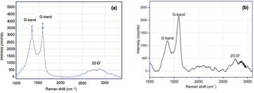
Table presents the porosity properties of various carbon samples based on coconut shell charcoal. It can be seen that the surface area tends to increase after each tretment. The increase in surface area after the treatment may also confirm the formation of multi-layer. The surface area of coconut shell charcoal was 189.97 m2/g. It increased to 496.03 m2/g after being successively activated with KOH and oxidized with the modified-Hummer method (AC-H). The surface area increased further 642.50 m2/g after it was reduced with citric acid (AC-H-R). The pore volume had the same tendency as the surface area while the pore diameter was relatively unchanged after each treatment.
Table 2. The porosity properties of various carbon samples
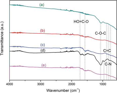
Figure shows the FTIR spectra of coconut shell charcoal (CSC) and the coconut charcoal treated by different treatments. The spectrum of CSC had a peak at 873 and 1615 cm–1 corresponding to C=C bond (aromatic group) (Zeng et al., Citation2011). The C=C bond was broken after the charcoal was activated with KOH (AC) and further with the modified-Hummer method (AC-H) and citric acid reduction (AC-H-R) as indicated by the disappearance of the band after the treatment. For all samples treated with only the modified-Hummer method or further with citric acid reduction, there are peaks at 2890, 1049 and 830 cm–1 that can be attributed to, respectively, C-H groups, C-O groups, and C-N groups (Tang et al., Citation2012). All functional groups are the typical groups encountered in GO or rGO. Thus, it can be assumed that graphene-like material had been successfully prepared from coconut shell charcoal by first activation and followed by the modified-Hummer method plus citric acid reduction.
Figure 5. FTIR spectra of various carbons: (a) AC, (b) AC-H), (c) coconut shell charcoal (CSC), (d) H-AC, and (e) AC-H-R
3.2. Capacitance properties
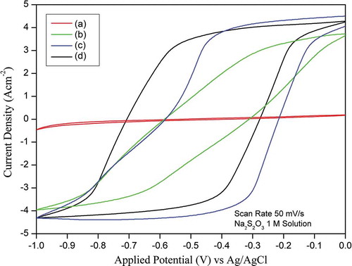
Figure shows the CVs for CSC, AC-H, H-AC, and AC-H-R in 1 M Na2S2O3 at a scan rate of 50 mV/s. An ideal double-layer capacitance of an electrode should exhibit a rectangular shape of CV. However, instead of a typical rectangular shape, a deviation, but still close to, a rectangular shape was observed. The CV enclosed area of CSC is very small, indicating the material is not suitable for use as supercapacitor. On the other hand, the CV enclosed area of AC-H is much larger than that of CSC and it increases further for AC-H-R, indicating that it has a much higher capacitance. It appears that graphene-like sample (AC-H-R) is suitable as an electrode material for supercapacitor.
The specific capacitance values were calculated from the CVs using the equation
where I is the cathodic current, V is the applied potential, m is the electrode mass, s is the scan rate and R is the scan range of applied potential. The specific capacitance values of CSC, AC-H, H-AC and AC-H-R calculated from Figure using EquationEquation (1)(1)
(1) were 3.22, 49.38, 86.32, and 148.20 F/g, respectively. The specific capacitance could be improved from 3.22 F/g to 49.38 and 86.32 F/g by activating the CSC followed with oxidizing using the modified-Hummer method (AC-H) and oxidizing using the modified-Hummer method followed by calcination (H-AC). The specific capacitance could be enhanced further from 86.32 to 148.20 F/g by reducing AC-H with citric acid (AC-H-R). The specific capacitance of carbon-based electrodes derived from natural resources reported in the published literature is typically in the range from 100 to 479 F/g (Ghosh et al., Citation2019). The high specific capacitance indicates that AC-H-R sample prepared from coconut shell charcoal using successively treatments of activation, oxidation, and reduction is a promising material for supercapacitor.
Figure 6. Cyclic voltammogram of (a) CSC, (b) AC-H, (c) H-AC, and (d) AC-H-R in 1 M Na2S2O3 at a scan rate of 50 mV/s
4. Conclusion
It has been demonstrated that porous graphene-like materials with high-surface area can be prepared from renewable coconut shell charcoal via KOH activation followed by oxidation in a harsh environment using a modified-Hummer method. The surface area of the treated coconut shell charcoal increased significantly from about 189.97 m2/g to 642.45 m2/g with a pore diameter of approximately 5 nm. The increase in surface area leads to an increase in the capacitance of this material in 1 M Na2S2O3 significantly from 3.22 F/g for coconut shell charcoal to 148.20 F/g for graphene-like material. These results demonstrated that the low cost renewable porous graphene-like material prepared from coconut shell charcoals is promising for use as electrode material for supercapacitor.
Cover Image
Source: Author
Cyclic voltammogram of (a) CSC, (b) AC-H, (c) H-AC, and (d) AC-H-R in 1 M Na2S2O3 at a scan rate of 50 mV/s

Acknowledgements
This work was supported by the Ministry of Research, Technology and Higher Education of Indonesia through PMDSU research grant (No. 01/E/KPT/2018) and a World Class Research grant (No. 713/PKS/ITS/2019). One of the authors (F. F.) would like to thank the Ministry of Research, Technology and Higher Education, Indonesia for a doctoral scholarship through PMDSU.
Additional information
Funding
Notes on contributors
Heru Setyawan
The research interest in our laboratory range from the preparation of advanced functional materials for energy, environment and biomedical, especially, from natural resources and solid waste using various methods such as electrochemical, electrospinning, and electro spray. Examples of advanced functional materials we are developing including electrocatalyst for oxygen reduction reaction, catalyst for esterification, high capacity liquid absorbents, etc. This paper is part of our project on developing carbon-based electrode materials from renewable biomass resources including coconut shells, coir fibers, bagasse, etc.
References
- Babu, S. V., & Seehra, S. (1996). Modeling of disorder and X-ray diffraction in coal-based graphitic carbons. Carbon, 34(10), 1259–9. https://doi.org/10.1016/0008-6223(96)00085-1
- De Silva, K. H., Huang, H. H., Joshi, R. K., & Yoshimura. (2017). Chemical reduction of graphene oxide using green reductants. Carbon, 119, 190–199. https://doi.org/10.1016/j.carbon.2017.04.025
- Dubale, A. A., Su, W. N., Tamirat, A. G., Pan, C. J., Aragaw, B. A., Chen, H. M., … Hwang, B. J. (2014). The synergetic effect of graphene on CuO2 nanowire arrays as a highly efficient hydrogen evolution photocathode in water splitting. Journal of Materials Chemistry A, 24(43), 18383–18397. https://doi.org/10.1039/C4TA03464C
- Ghosh, S., Santhosh, R., Jeniffer, S., Raghavan, V., Jacob, G., Nanaji, K., Kollu, P., Jeong, S. K., & Grace, A. N. (2019). Natural biomass derived hard carbon and activated carbons as electrochemical supercapacitor electrodes. Scientific Reports, 9(1), 16315. https://doi.org/10.1038/s41598-019-52006-x
- Girgis, B. S., Temerk, Y. M., Gadelrab, M. M., & Abdullah, I. D. (2007). X-ray diffraction patterns of activated carbons prepared under various conditions. Carbon Letters, 8(2), 95–100. https://doi.org/10.5714/CL.2007.8.2.095
- Gou, G., Huang, F., Jiang, M., Li, J., & Zhou, Z. (2020). Hierarchical porous carbon electrode materials for supercapacitor developed from wheat straw cellulosic foam. Renewable Energy, 149, 208–2016. https://doi.org/10.1016/j.renene.2019.11.150
- Khrisnamoorthy, K., Veerapandian, M., Yun, K., & Kim, S. J. (2013). The chemical and structural analysis of graphene oxide with different degrees of oxidation. Carbon, 53, 38–49. https://doi.org/10.1016/j.carbon.2012.10.013
- Pradhan, B. K., & Sandle, N. K. (1999). Effect of different oxidizing agent treatments on the surface properties of activated carbons. Carbon, 37(8), 1323–1332. https://doi.org/10.1016/S0008-6223(98)00328-5
- Przygocki, P., Abbas, Q., & Beguin, F. (2018). Capacitance enhancement of hybrid electrochemical capacitor with asymmetric carbon electrodes configuration in neutral aqueous electrolyte. Electrochimica Acta, 269, 640–648. https://doi.org/10.1016/j.electacta.2018.03.016
- Shui, J., Wang, M., Du, F., & Dai, L. (2015). N-doped carbon nanomaterials as durable catalysts for oxygen reduction reaction in acidic fuel cells. Science Advances, 1(1), 1–7. https://doi.org/10.1126/sciadv.1400129
- Sun, L., Tian, C., Li, M., Meng, X., Wang, L., Wang, R., Yin, J., & Fu, H. (2013). From coconut shell to porous graphene-like nanosheets for high-power supercapacitors. Journal of Materials Chemistry, 23(21), 6462–6470. https://doi.org/10.1039/c3ta10897j
- Tang, Y., Huang, F., Zhao, W., Liu, Z., & Wan, D. (2012). Synthesis of graphene-supported Li4Ti5O12 nanosheets for high rate battery application. Journal of Materials Chemistry, 22(22), 11257–11260. https://doi.org/10.1039/c2jm30624g
- Toh, S. Y., Loh, K. S., Kamarudin, S. K., & Wan Daud, W. R. (2014). Graphene production via electrochemical reduction of graphene oxide; Synthesis and characterization. Chemical Engineering Journal, 251, 422–434. https://doi.org/10.1016/j.cej.2014.04.004
- Vieira, M. A., Gonvcalves, G. R., Cipriano, D. F., Schettino, M. A., Filho, E. A. S., Cunha, A. G., Emmerich, F. G., & Freitas, J. C. C. (2016). Synthesis of graphite oxide from milled graphite studied by solid-state 13C nuclear magnetic resonance. Carbon, 98, 496–503. https://doi.org/10.1016/j.carbon.2015.11.037
- Yang, C.-S., Jang, Y. S., & Jeong, H. K. (2014). Bamboo-based activated carbon for supercapacitor applications. Current Applied Physics, 14(12), 1616–1620. https://doi.org/10.1016/j.cap.2014.09.021
- Zeng, F., Sun, Z., Sang, X., Diamond, D., Lau, K. T., Liu, X., & Su, S. (2011). In situ one-step electrochemical preparation of graphene oxide nanosheet-modified electrodes for biosensors. ChemSusChem, 4(11), 587–591. https://doi.org/10.1002/cssc.201100319
- Zhao, B., Song, J. L., Xu, W., Fang, T., Jiao, Z., Zhang, H., & Jiang, Y. (2011). Monolayer graphene/NiO nanosheets with two-dimension structure for supercapacitors. Journal of Materials Chemistry, 21(46), 18792–18798. https://doi.org/10.1039/c1jm13016a
- Zhao, C., Huang, Y., Zhao, C., Shao, X., & Zhu, Z. (2018). Rose-derived 3D carbon nanosheets for high cyclability and extended voltage supercapacitors. Electrochimica Acta, 291, 287–296. https://doi.org/10.1016/j.electacta.2018.09.136
- Zhu, X., Yu, S., Xu, K., Zhang, Y., Zhang, L., Lou, G., Wu, Y., Zhu, E., Chen, H., Shen, Z., Bao, B., & Fu, S. (2018). Sustainable activated carbons from dead ginkgo leaves for supercapacitor electrode active materials. Chemical Engineering Science, 181, 36–45. https://doi.org/10.1016/j.ces.2018.02.004