
 ?Mathematical formulae have been encoded as MathML and are displayed in this HTML version using MathJax in order to improve their display. Uncheck the box to turn MathJax off. This feature requires Javascript. Click on a formula to zoom.
Abstract
Energy efficient building envelopes are essential for sustainable development in civil engineering and architecture. In this preliminary investigation, a structural building envelope that is load bearing is developed for daylight harvesting. A translucent concrete panel (TCP) design is constructed using optical fibers (OFs) to transmit light and common concrete mix design. A steel mesh is embedded in the TCP to increase its structural load bearing capacity. It has the potential to save energy and reduce carbon footprint by collecting, channeling and eventually scattering the sunlight. Constructability issues including mechanical and optical losses are analyzed and discussed. Numerical models of the single OF and the whole TCP are developed using ray tracing software and the light transmission mechanisms are analyzed. Nonimaging sunlight collectors, namely compound parabolic concentrator (CPC), together with the OFs represent an efficient system for harvesting and guiding the sunlight into the interior spaces. The light transmission of a model made out of a CPC and an OF is evaluated from an energy efficiency point of view.
PUBLIC INTEREST STATEMENT
Energy efficient building envelopes are essential for sustainable development in civil engineering and architecture. A translucent concrete panel (TCP) is constructed using optical fibers (OFs) to transmit light and common concrete mix design. It has the potential to save energy and reduce carbon footprint by collecting, channeling and eventually scattering the sunlight. Constructability issues including mechanical and optical losses are analyzed and discussed. Numerical models of the single OF and the whole TCP are developed using ray tracing software and the light transmission mechanisms are analyzed. Compound parabolic concentrator (CPC) and the OFs represent an efficient system for harvesting and guiding the sunlight into the interior spaces. The light transmission of a model made out of a CPC and an OF is evaluated from an energy efficiency point of view. The results will help to develop energy efficient buildings.
1. Introduction
The translucent concrete panel (TCP) in this study has a certain amount of optical fibers (OFs), either glass or plastic core, embedded and regularly aligned in concrete. OFs transmit light through the concrete panel. The “translucency degree” of the TCP depends on the density of the embedded OFs. It is to be noted that for plastic OF, the core can be polystyrene or polymethylmethacrylate and the cladding is generally silicone or Teflon. On the other hand, for glass OF, both the cladding and the core are made of Silica with small amount of dopants, e.g., Boron or Germanium, to change its index (Lacy, Citation1982).
TCP is a new building material; it came into being at the beginning of this century for building decoration. In 2001, Hungarian architect Aron Losonzi invented LiTraCon™, the first commercially available form of translucent concrete (Litrocon Ltd Citation2012). It is a combination of OFs and fine concrete, combined in such a way that its appearance is perceived as homogeneous. LiTraCon™ is manufactured in blocks and panels for decoration. Litracon pXL® is a slightly different product, offered by the same company, that uses Polymethyl methacrylate in place of glass OFs. In Shanghai 2010 EXPO, Italy took the opportunity to build its pavilion out of translucent concrete (TC) using about 4,000 i.light® blocks, each 100 cm × 50 cm × 5.0 cm (Bates, Citation2010; Hipstomp, Citation2010). The blocks were heavier than glass panel as the façade in buildings. In the standard products of the same manufacturer, there are also 120 cm × 60 cm panels with 1.5 cm or 3.0 cm thickness (Lucem Lichtbeton, Citation2018). These thinner products are suitable for building façades and are generally laminated with light-emitting diode plates for commercial advertising. Another product features plastic fibers arranged in a regular grid, namely Pixel Panels, developed by Bill Price of the University of Houston (Klemenc, Citation2011). These panels transmit light from one face of a wall to the other, but in a pattern, where light that shines through the panel resembles thousands of tiny stars in a night sky. University of Detroit-Mercy also developed a process to produce translucent panels made out of Portland cement, sand and reinforced with a small amount of chopped fiberglass [6]. The primary focus of the TC technology has previously been on its aesthetic appeal and its application in artistic design. Few people study on its light transmitting, mechanical and self-sensing properties and long-term durability of the material (Ahuja et al., Citation2015; He et al., Citation2011; Mead & Mosalam, Citation2017; Mosalam & Nuria, Citation2018). However, a comprehensive experimental study of TCP is not yet developed to address the issue of daylight harvesting property.
Nowadays, sustainable development has become an inevitable trend in every walk of society (Loonen et al., Citation2017), including civil engineering and architecture. Therefore, development and use of sustainable materials, which are green, energy efficient and low-cost, are gaining more interest. The building envelope defines the interior environment. Thus, the energy efficiency of the envelope affects the efficiency of the entire building system. Furthermore, if the envelope can capture more daylight into the building, the electric lighting load can be reduced and further energy savings are achievable. Compared to a traditional electric lighting system, daylight is more energy efficient and more appealing for a healthy environment and human productivity and comfort because it contains almost the full spectrum of the sunlight (Edwards & Torcellini, Citation2002).
TCPs with sunlight concentrators provide the possibility of concentrating and transmitting sunlight into the indoor environment. In this way, the building envelope subsystem saves energy and reduces carbon footprint by collecting and distributing sunlight without reducing its bearing capacity. Nonimaging sunlight collectors, e.g., compound parabolic concentrator (CPC) (Chaves, Citation2008; Winston et al., Citation2005), and light conduits harvest and guide sunlight into the interior spaces. Artificial lighting load can then be significantly reduced. Construction of the proposed TCP, its light transmission simulation and experiments are discussed in the paper.
2. Design and construction of TCP
The construction process of TCPs is different from that of traditional concrete panels due to the existence of the OFs. The spatial arrangement of the OFs and the reinforcement is critical during the whole process. More advanced TCPs will be developed and studied in future work.
2.1. Clear distance between OFs
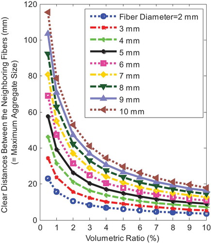
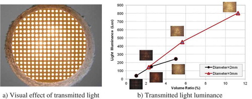
There is a relationship between the clear distance of two neighboring fibers, the diameter of the used OFs, and the intended volume ratio (density of the parallel fibers) of the OFs embedded in the TCP, refer to Figure . This clear distance affects the constructability of the TCP. When the value of this distance is smaller than the specified maximum aggregate size of the concrete, it would be hard to place the concrete. Moreover, from a load bearing capacity point of view, smaller density and smaller diameter of OFs imply less chances of inborn defects, improving the structural performance. On the other hand, smaller diameter fibers require intense labor and smaller density of OFs in the TCP reduces its light transmission property. Therefore, there should be a balance among the above issues. For the first TCP in this study, concrete without coarse aggregate, i.e., mortar, was initially used to temporarily avoid these issues where 5% volume ratio of OFs with 2 mm diameter were used.
Figure 1. Effect of volume ratio on the clear distance between the OFs of different diameters
2.2. Formwork and construction
Acrylic plates were used to construct the form of the TCP. Holes were drilled into the plates to provide cavities for the OFs. The dimension of the TCP was selected as 30.5 cm × 30.5 cm, and its depth was 7.6 cm. The clear distance between the OFs was 8 mm leading to 1,600 holes in the TCP; refer to Figure . After the holes were drilled in the two large acrylic plates, OFs were inserted into the holes in these two plates. Figure shows the finished form. In order to reinforce the TCP, steel wire mesh was placed in the middle of the panel. Upon completion of the form, common mortar mix was placed in the form, Figure .
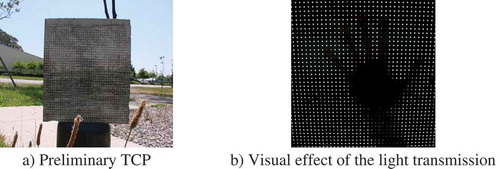
The panel was placed into the curing room for 7 days before removing the form, Figure . The panel looks similar to traditional concrete panels at first sight. However, when placed in daylight or other light source, its light transmission performance is easily identified, Figure .
Figure 2. Formwork and construction of the TCP
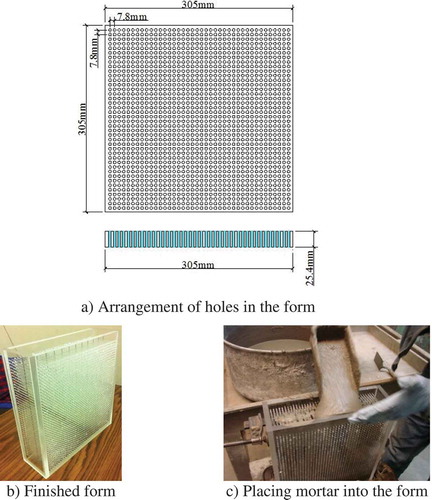
Figure 3. Finished TCP
3. Light transmission analysis of the optical fibers
Due to the OFs, the TCP has the ability to transmit light. Therefore, understanding the light transmission properties of the OF is a prerequisite for analyzing the light transmission properties of the whole TCP.
3.1. Optical fibers
3.1.1. Working mechanism of OFs
In TCP, OFs are used for light transmission. The target is transmitting and guiding the light where OFs behaved as light conduits. Understanding the characteristics of different fiber types is useful in understanding the applications for which they are used (Alwayn, Citation2004; Goff, Citation2002; Industrial Fiber Optics, Inc, Citation2002). There are three basic types of OFs: multimode graded-index fiber, multimode step-index fiber and single-mode step-index fibers. Only large diameter single mode OFs were used in this study because of its low cost and availability from the market. OFs provide a method of transmitting light through long thin fibers of glass or plastic by a phenomenon known as total internal reflection, refer to Figure . It achieves this by essentially having a perfect mirror coating the outside of an internal transparent core. The light enters one end of the OF and hits the inside of the outer cladding which has a lower index of refraction. For incidence angle between the boundary and the light ray less than the critical angle, the light is reflected back into the fiber. This is referred to as total internal reflection (TIR) and thus light travels down the length of the fiber, i.e., the fiber does not have to be straight.
Figure 4. Light transmission in graded-index single mode fiber [14]
![Figure 4. Light transmission in graded-index single mode fiber [14]](/cms/asset/f129681c-33d5-49a3-94f7-214d50984ab4/oaen_a_1756145_f0004_oc.jpg)
3.1.2. Acceptance angle and numerical aperture
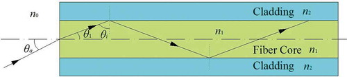
Numerical aperture is a parameter that is often used to specify the acceptance angle of a fiber (Hui & O’Sullivan, Citation2009). Figure shows an axial cross-section of a step-index fiber and a light ray that is coupled into the fiber left cross-section, where n1, n2, are refractive indices of the fiber core, and cladding, respectively. For the light to be coupled into the guided mode in the fiber, total internal reflection has to occur inside the core requiring , as shown in Figure , where
is the critical angle of the core-cladding interface. With this requirement on
, there is a corresponding requirement on incidence angle
at the fiber end surface making use of Snell’s law and elementary trigonometry, i.e.,
Figure 5. Light transmission in the step index fiber
If the total internal reflection occurs at the core-cladding interface, we have , i.e.,
. This requires the incidence angle
to satisfy the following condition [18]:
where the definition of numerical aperture (NA) is . The light, entering an OF within a cone defined by the half-acceptance angle,
, is converted into guided modes and can propagate along the fiber. Outside this cone, the light coupled into a fiber will radiate into the cladding. Similarly, the light exiting a fiber has a divergence angle defined by the numerical aperture. This property is critical for the fiber for capturing daylight.
3.2. Light transmission simulation of OFs
The detailed information of the OFs in the TCP is listed in Table . Solid models of straight and bent fiber were created with TracePro software (TracePro 72, Citation2012). In this section, light transmission analysis was conducted for a 2 mm diameter fiber with 12.7 mm length, which is the thickness of the wood panels, discussed in Section 4.1.
Table 1. Properties of the optical fibers
3.2.1. Straight OF
The ideal spatial arrangement of each OF in the TCP is straight because it will avoid light loss due to bending. Therefore, the light tracing in the OF and its efficiency should be confirmed during light transmission. OF model was created (Figure ) according to the properties listed in Table . The boundary of the light grid source was taken as annular (Figure ) because the acceptance cone of the OF is rotationally symmetric, and if the OF is connected to the CPC, the light rays irradiating from the exit aperture will also be rotationally symmetric. In order to simulate the daylight, random distribution of incident rays was selected because it is very close to the daylight distribution (uniform distribution of rays has similar results). One hundred rays in total and 0.01 W per ray were considered to model different incidence angles from 0° to 50°. Since NA = 0.5, Table , the half acceptance angle, , is 30° for
(EquationEquation 2
(2)
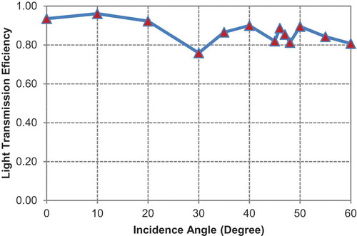
(2) ). Figure exhibits the light transmission efficiency variation with different incidence angles. This efficiency is defined as the ratio of the light luminance at the entrance section to that at the exit section. It is observed that the light transmission efficiency with all analyzed angles is below 1.0 because of the reflection at the entrance section of the OF regardless of the incidence angle. For incidence angle of 30°, the light transmission efficiency is the lowest at about 0.76. Moreover, for light incidence angles smaller or larger than 30°, the light transmission efficiency increases to 0.96 at 10° and 0.90 at 40° and fluctuates around 0.85 for incidence angles > 40°. This fluctuation is attributed to the random distribution of the incident rays where increasing the incidence angle lead to smaller number of rays generated outside the acceptance cone of the OF and more rays stayed inside the cone and were transmitted. Therefore, the transmission efficiency slightly increased compared to the cases of smaller incidence angles.
It is noted that the incidence of daylight rays is random. Although rays come from many different directions, the preferred direction is a uniform extending from many directions from the sun. Also, the daylight and illumination conditions of a given place are different depending on its location, factors as latitude and season influence illumination, the angle of sunrays are not the same for a place located on the equator compared for a place in Northern Europe or Australia. The direction of sunrays will be different in summer and winter. These factors should be considered when analyzing the light transmission properties of the TCP in different locations.
Figure 6. Light transmission simulation of a single fiber
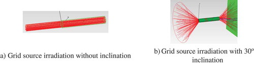
Figure 7. Variation of light transmission efficiency with incidence angle
3.2.2. Bending of OF
In the actual construction process, bending disturbance of the OF is unavoidable because of the vibration, handling, and other unexpected conductions. As such, mechanical damage and optical loss occur. These effects are discussed in this section.
3.2.2.1. Mechanical stress analysis
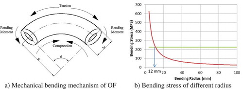
This analysis is similar to the case of steel reinforcing bar where the mechanical bending analysis is related to bending radius and bar diameter. In this case, the deflection of the OF is the main factor in the bending mechanism, Figure . From elementary mechanics, the bending stress can be calculated as follows:
where is the bending stress,
is Yong’s modulus of the OF,
is the radius of the OF, and
is the bending radius of the OF. According to EquationEquation (3)
(3)
(3) , the relationship between the bending radius and the bending stress is shown in Figure where the horizontal line is the tensile strength of the OF being studied,
mm and
MPa. The bending stress will be lower than the tensile stress of the OF if the bending radius is larger than 12 mm, a suggested lower limit of the bending radius is 20 mm corresponding to a safety factor of 20/12 = 1.67 for structural safety of the OFs. In practice, the long-term service conditions should be considered as discussed in literature (Galesemann & Castilone, Citation2002; Matsui et al., Citation2010).
Figure 8. Mechanical stress analysis of bent OF
3.2.2.2. Optical analysis
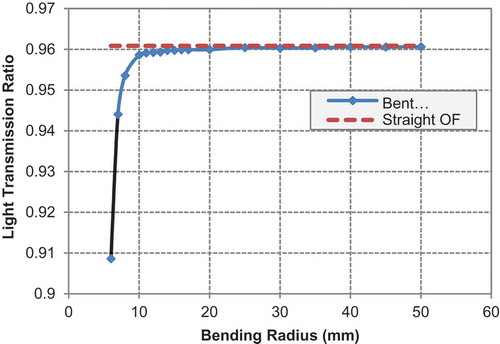
It is obvious that bending of OFs causes loss of light rays and reduces its light transmission performance. Therefore, minimizing loss due to bending is important in arranging the OFs in the TCP. Bending loss for various wavelengths and bending parameters, e.g., radius of curvature and wrapping turns, have been reported in (Gupta, Citation2005). It is well-known that loss increases with bending especially for long wavelengths. Research also showed that temperature and presence of protection layer can affect the bending loss (Tangnon et al., Citation1989; Wang et al., Citation2005). Different models have been suggested based on fitting experimental results but due to variation of bending loss with radius of curvature, some disagreement between the theoretical modeling and the actual experimental results were reported (Renner, Citation1992). There are standard specifications (Telecommunications Industry Association, Citation2009) for small diameter OFs used for communications because their cladding is very large compared to the core. These specifications require that the bending radius should be larger than 15 times the diameter of the OF. This agrees with the numerical analysis results from TracePro software where almost all the rays were transmitted by the fiber with this bending radius limitation as illustrated in Figure .
Considering the mechanical (Figure ) and optical (Figure ) requirements, it is obvious that the optical property controls the bending limit of the OF. The bending radius should be greater than 15 times the diameter (30 mm in this study) of the OF. This should be followed during the manufacturing process of the TCP.
Figure 9. Optical analysis of the bending
4. Light transmission performance
After understanding the light transmission mechanism of the OF and its constructability limitation, the next step is to study the light transmission behavior of the TCP. This is conducted in the present section.
4.1. Light irradiation test
4.1.1. Test setup
The existence of the OFs plays a major role in the light transmission behavior of the TCP. Therefore, presence of enclosing materials such as concrete becomes unimportant. For practicality of the study and to focus on the light transmission issue, several hard wood panels (178 mm × 178 mm) were constructed and used instead of concrete panels for ease of construction. A certain number of holes were predrilled for a specific volume ratio, Table . OFs with 2 mm and 3 mm diameters were inserted in these holes. Two wood boxes were fabricated to simulate a small room. One box was painted black in the inside and outside while the other box was painted white, Figure . An incandescent lamp (80 W) was installed in front of each box facing the TCP side (although the panels were made of wood, we continue to refer to these light transmitting panels as TCPs herein) to simulate the sunlight, Figure . A 76 mm diameter hole was drilled on the opposite side of the TCP for installing the sensor of the light meter, Figure .
Figure 10. Test setup for light irradiation tests
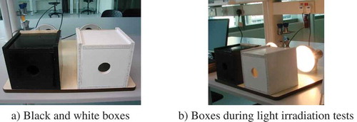
Table 2. Volume ratio of wood panels in place of the TCPs for convenience
4.1.2. Results and discussions
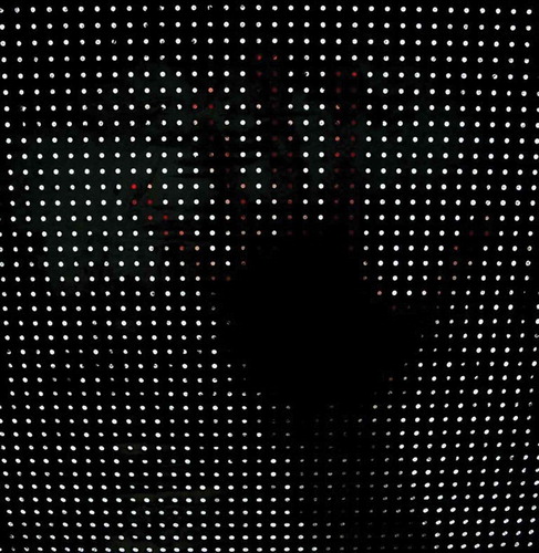
Each TCPs was inserted into the front side of each of the two boxes and the transmitted light was observed through the hole in the back side of the box, Figure . Experimental results are shown in the Figure . From the results shown in this figure, several observations can be made: (1) independent of the color of the box (white or black), the light transmission ability of the TCP increased with the volume ratio of the OFs, (2) due to the higher reflection index, the light intensity observed from the white box is larger than that from the black box, and (3) panels with lager diameter OFs transmit more light than the ones with smaller diameter OFs.
Figure 11. Experimental results of irradiation tests of TCPs
4.2. Light irradiation simulation
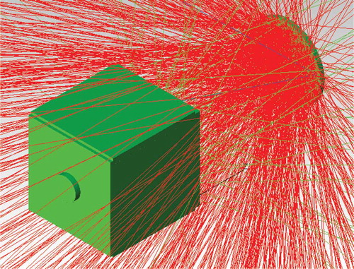
The light transmission performance of the TCP in the small box was modeled with TracePro software. Computational results are compared to the experimental results for validation of the computational model and for subsequent optimization of the design of the panel.
4.2.1. Model description
Three models were created with TracePro software. Two of these models represented the black and white wooden boxes. The third model is also a wood box without any painting. For these three models, the reflection indices are 0.2 for the black painting, 0.9 for the white painting, and 0.6 for the case without painting. Due to lack of information related to the angular distribution of the used incandescent lamp in the tests, standard surface light source, namely CREE C450TR3041 as defined in TracePro 72, was adopted instead, refer to Figure .
Figure 12. Numerical model of the irradiation test
4.2.2. Results and discussions
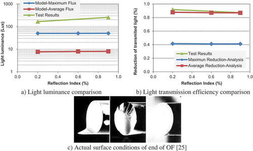
Because of the difference between the light source of the numerical and the physical models, the computed and measured flux values through the observation hole were expected to be different, Figure . It is to be noted that the box can be viewed as a light attenuation medium where the light approaching the OF surface in the TCP is transmitted into the box and finally arrives at the observation hole. Due to light reflection and refraction, the light intensity is expected to be reduced. For comparison, a flux reduction ratio is defined as follows,
where is the flux reduction ratio,
is the surface flux of the TCP, and
is the flux at the location of the observation hole.
Light transmission efficiency of the modeled three boxes is plotted in Figure . From these results, the following observations can be made: (1) the internal painting of the box slightly affects the reduction ratio where the higher the reflection index, the smaller the reduction ratio, . This is observed from both tests and numerical results, (2) the reduction factor of the maximum flux is smaller than that of the average flux and (3) the reduction ratio from the tests is larger than that from the simulation. Several reasons contributed to the differences between the experimental and numerical results. These are: (1) the source of light for the model is different from that for the test, (2) the light distribution on the observation hole is not even, (3) the spatial propagation of the Incandescent lamp used in the tests and the CREE light used in the simulations are different, (4) the lightmeter should be placed right in front of the TCP to test the incident flux. However, in reality, the luminance sensor was placed at a distance (about 10 mm) from the surface of the TCP. Therefore, the measured values are expected to be smaller than the actual values, and (5) rough surfaces of the actual OFs due to the cutting process occurred, Figure , affecting the light acceptance and scattering [29]. Accordingly, a number of light rays scattered to the interior surfaces of the box. Some of these rays were reflected and then arrived at the observation hole. Therefore, the test results were affected by the color of the box. On the other hand, the numerical model did not take into consideration the surface roughness of the OFs cross-sections. By checking the paths of the rays arriving at the observation hole, most of the light rays directly irradiated from the exit surfaces of the OFs where a small number of light rays were reflected to the internal surfaces of the box.
For the black, no paint, and white boxes, the reflected rays contained approximately 20%, 60%, and 90%, respectively, of the total energy compared to the incident energy. Therefore, due to the rough surfaces of the OFs, a large amount of reflected rays (reflected more than twice) arrived to the observation hole. Accordingly, the measured flux value varied with the reflection index, Figure . On the other hand, the flux from the numerical model was insensitive to the reflection index because the rays containing full energy arrived to the observation hole with much less reflection due to the smooth cross-section of the modeled OFs.
In summary, the light irradiation simulation demonstrated the need to improve the light transmission experiments. The accuracy of the physical model should be improved in the following respects:
1) The surfaces of the OFs should be smooth using high-quality cutting machine.
2) Reflection index of the interior surfaces of a tested box should be accurately determined.
3) Standard light source should be used in experiments.
4) The light test sensors need to be improved and installed properly for acquiring reliable results.
Figure 13. Comparison of light irradiation results and source of difference between experimental and numerical values
5. Integration of compound parabolic concentrator
Due to the small cross-section and limited amount of OFs in a typical TCP, such panels cannot capture light beyond the acceptance cone of the OF. Horizontally arranged OFs in a TCP are efficient to capture the light rays parallel to the OF length, i.e., perpendicular to the OF cross-section, in multi-story buildings. For the TC façade with horizontally distributed OFs, it is ideal for the OF to face the light source (sun) to capture direct light rays. This is because horizontally irradiating rays from the light source can easily enter the acceptance cone. Although horizontal OF can capture all rays, which fall into its light acceptance cone, non-horizontal rays are reflected ones and have lower energy content than direct rays from the sun. An efficient light concentrator, e.g., CPC needs to be integrated with OF to enhance the light concentration.
5.1. Working mechanism of CPC
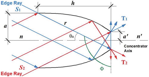
CPC is a cone-shaped solar concentrator analyzed here using the edge-ray principle from research originally conducted in the mid-1960 s, which became fully developed in the 1970s and 1980s (Miñano, Citation1985, Citation1986; Miñano et al., Citation1983; Mitschke, Citation2009; Ries & Rabl, Citation1994). CPC is a nonimaging (anidolic) concentrator that is almost ideal having the maximum theoretical concentration ratio.
Two-dimensional (2D) hollow CPCs [13] follow the similar working mechanism as 3D solid ones. Rays S1 and S2, which are parallel to the edge rays, come to the entrance aperture of the CPC and arrive to the parabolic internal surface. Subsequently, S1 and S2 are reflected to the exit aperture while the edge rays arrive to the exit aperture directly without any reflections. Therefore, the light concentrates from the bigger entrance aperture to the smaller exit aperture, Figure . In this figure, T1 and T2 are the exit rays of the entrance edge rays S1 and S2.
The governing equations of the meridian section of a CPC are developed by rotation of axes and translation of origin. A compact parametric form can be presented by making use of the polar equation of the parabola. Figure defined the key variables used in developing the meridian section as given by EquationEquation (5)(5)
(5) to EquationEquation (8)
(8)
(8) .
Substituting EquationEquation (5)(5)
(5) into EquationEquation (6)
(6)
(6) and simplifying by making use of EquationEquation (7)
(7)
(7) ,
can be expressed as follows,
where is the focal length,
is the radius of the entrance aperture,
is the radius of the exit aperture,
is the half-acceptance angle of the CPC, n-n’ is the concentrator axis, and
is its total length. The polar coordinates
needed to design and plot the CPC are shown in Figure (Winston et al., Citation2005). In the TCP,
and
are determined by the panel design (thickness and OF diameter). Once
is selected, EquationEquations (5)
(5)
(5) and (Equation7
(7)
(7) ) can be used to determine
and
, respectively. Subsequently, EquationEquation (6)
(6)
(6) or EquationEquation (8)
(8)
(8) can be used to obtain the corresponding
. The real CPC herein is 3D; it is defined as the shape swept out when the shape profile of the 2D CPC is rotated about its symmetry axis
Figure 14. CPC with edge-ray principle
The maximum concentration ratio, , is useful to determine the concentration ability of the CPC to be designed. It is the ratio of the area of the entrance aperture to that of the exit aperture. For a circular aperture, it is defined in EquationEquation (9)
(9)
(9) for 3D geometry (Chaves, Citation2008; Winston et al., Citation2005). It is noted that for hollow CPC in air, the refraction indices
and
are both equal to 1.0. In this case,
is entirely determined by the half-acceptance angle of the CPC, e.g., if
, then
. For 2D CPC, the squares in EquationEquation (9)
(9)
(9) should be dropped.
5.2. Introducing CPC in the TCP
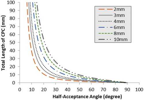
There are three key factors to determine the optimal shape of the CPC. For a TC building façade, the total length is limited by the actual depth of the panel and the exit aperture
is limited by the diameter of the selected OF. Several types of OFs are available with diameters varying from < 2 mm to 20 mm. The third key factor is the half-acceptance angle,
, which is related to the total length,
, or the entrance aperture,
, for a known exit aperture radius,
, as given by EquationEquation (6)
(6)
(6) and (Equation7
(7)
(7) ), respectively. The relationship between
and
is plotted in Figure for different values of
by making use of EquationEquations (5)
(5)
(5) and (Equation6
(6)
(6) ). From this figure, the following observations can be made: (1) the acceptance angle reduces rapidly with the increase of the CPC total length, (2) a CPC with a known length has a larger acceptance angle for a larger exit aperture radius, and (3) a CPC with a known acceptance angle is larger in length for a larger exit aperture radius. From a constructability point of view, a CPC total length of 10–80 mm is acceptable for typical TCP thicknesses. The half-acceptance angle is between 10° and 20° for
2 mm taken as the OF diameter, refer to Figure . Clearly, larger diameter OF is more ideal where the half-acceptance angle can be easily increased to 40°, Figure . It is to be noted that bundles of OFs can be used to accept the light rays concentrated on the exit aperture of the CPC. However, several issues have to be resolved: (1) given the dimensions of the panel, the optimal shape of the CPC should be determined to define the exit aperture for placement and determination of the number of the OFs, (2) the cross-section of the OF bundle is not closed and light will leak out from the spaces between the OFs and the boundary of the exit aperture, and (3) need to define the method of binding the OFs together.
Figure 15. CPC total length variation with the half-acceptance angle for different exit aperture diameter
The factor which evaluates the light concentration ability is the maximum concentration ratio defined in EquationEquation (9)(9)
(9) and plotted in Figure for a 3D CPC and for
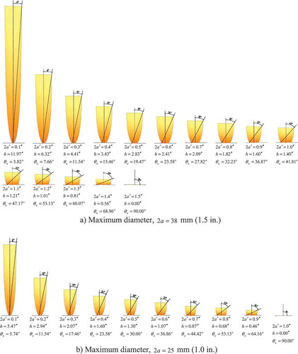
in a hollow CPC placed in air. From Figure , larger acceptance angle rapidly reduces the concentration ratio. For practical design of a CPC, a concentration ratio in the range 33.2 to 2.4 corresponds to half-acceptance angle in the respective range of 10°–40°. In the future, the CPC design will be optimized for the use in actual TCPs. A series of CPC designs are simulated and shown in Figure for different geometry (variety of the half-acceptance angles) and for two different maximum diameters (entrance aperture), namely, 38 mm (1.5 in.) and 25 mm (1.0 in.) (Commissioner of Building Control, Citation2004)
Figure 16. Concentration ratio of CPC
Figure 17. CPC with different geometry
5.3. Simulation of CPC and OF
In order to verify the sunlight concentration and transmission performance of the CPC with OF, an optimized model was developed with TracePro software as shown in Figure . The diameter of the OF (2 mm) determines the diameter of the exit aperture of the CPC. In order to achieve a high concentration ratio with reasonable half-acceptance angle (12.0°), the total length of the CPC is 27.3 mm, Figure , for a 2 mm exit aperture diameter similar to the diameter of the used OF in the TCP. It should be noted that half-acceptance angle of 12.0° is small for practical applications of CPC but used here for illustration purposes and for achieving high value of . From Figure , the corresponding maximum concentration ratio of the considered 3D CPC in air is
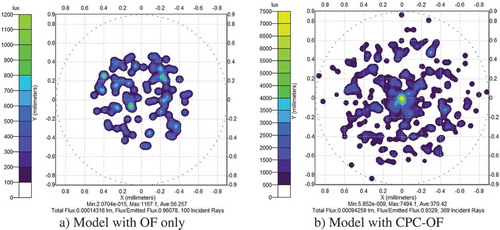
. The optical properties of the OF are taken to be the same as those in Table . Grid source is used in the simulation as shown in Figure indicating the inclined light rays with incidence angles equal to the half-acceptance angle of the CPC. Different number of rays were used to make sure the simulation results are accurate enough. From the simulation results, the luminance distributions of the OF end cross-section (right hand of OF shown in Figure ) are showed in Figure . From this figure, it is clear that including the CPC led to much higher efficiency in light transmission. From results in Figure , the following observations can be made: (1) the rays distribution area of the CPC-OF is obviously larger than the one for OF only and (2) the maximum Lux value of 7494 for the CPC-OF (Figure ) is 6.4 times that (1167 Lux) for the OF only (Figure ).
Figure 18. CPC and OF computational model
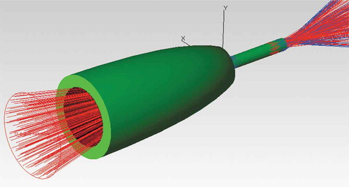
Figure 19. Illuminance maps at the exit cross-section of the OF from simulations
6. Concluding remarks and future extensions
A TCP is constructed using reinforced concrete (RC) and OFs. Daylight transmission is a distinctive property of the panel making it useable for energy-efficient building envelopes (Commissioner of Building Control, Citation2004). Such envelopes allow light to be transmitted into the rooms while having the potential of better envelope thermal transfer value (Chen et al., Citation2012). In order to study the light transmission performance of the TCP, the optical mechanism of the OF is analyzed theoretically, and a numerical model is developed to determine its light transmission properties. Constructability of the TCP is addressed considering mechanical and optical requirements and the critical bending radius is established. Small-scale “buildings” made up of wood boxes are constructed to simulate real buildings with TCP façade. The experimental and numerical results are discussed and compared. It should be mentioned that the smoothness of the OF ends are important for its light transmission function. The light capturing performance of the OF is limited because of its small cross-section, small range of light acceptance angles, and limited numbers of OFs in the TCP. Therefore, a CPC is introduced and integrated with the OF. Numerical analysis results demonstrated that this integration is beneficial in improving the light concentration performance of the TCP.
The preliminary TCP developed in this study gives an indication that energy efficiency of a building envelope is a feasible endeavor. CPC integrated with OFs can improve the light capturing ability, while the planar distribution of the CPC with OFs needs to be developed and optimized considering construction and economic constraints. The shape and dimensions of the CPC, either hollow or solid, are critical for the light concentration property of the TCP. Moreover, the design of the CPC can have implications on the loading bearing capacity of the TCP. Therefore, a balance between the optical and structural performances needs to be determined. Available commercial OFs are expensive. Therefore, low-cost light transmission pipe should be found to reduce the cost of the TCP. Finally, light irradiance and thermal insulation experiments with standard light source or under sunlight should be conducted (Kahsay et al., Citation2019; Littlefair, Citation1998).
Cover image
Source: Author.
Acknowledgements
The authors thank Mr. J. Hlavaty, Lambda Research Corporation for tireless assistance, Prof. Zhang Min-Hong, National University of Singapore, for kind assistance of manufacturing of the panels. The presented research is funded by the Republic of Singapore’s National Research Foundation through a grant to the Berkeley Education Alliance for Research in Singapore (BEARS) for Singapore-Berkeley Building Efficiency and Sustainability in the Tropics (SinBerBEST) Program. BEARS has been established by the University of California, Berkeley as a center for intellectual excellence in research and education in Singapore. This work was also supported by China National Science and Technology Major Project with grants # 2016YFE0105600, and China National Science Foundation with grants # 51578411, 51608381, 51578405, International Joint Research Laboratory of Earthquake Engineering (ILEE) through grant number ILEE-IJRP-P2-P3-2017.
Additional information
Funding
Notes on contributors
Baofeng Huang
Baofeng Huang is an associate professor of the College of Civil Engineering, Nanjing Tech University. He received his BSc degree (2003) from Jinan University, and his MS (2006) and PhD (2014) degrees from Tongji University. He studies seismic performance of the nonstructural systems, experimental approaches in structural engineering and energy‐efficient buildings.
References
- Ahuja, A., Mosalam, K. M., & Zohdi, T. I. (2015). Computational modeling of translucent concrete panels. Journal of Architectural Engineering, 21(2), 1–18. https://doi.org/10.1061/(ASCE)AE.1943-5568.0000167
- Alwayn, V. (ed). (2004). Optical network design and implementation. Cisco Press.
- Bates, D. (2010). Mortar this than meets the eye: The ‘transparent’ cement that lets daylight flood into a room. Retrieved Nov 24, 2012, from http://www.dailymail.co.uk/sciencetech/article-1344383/Transparent-light-cement-lets-light-flood-room.html
- Chaves, J. (ed). (2008). Introduction to nonimaging optics. CRC Press.
- Chen, F., Wittkopf, S. K., Ng, P. K., & Du, H. (2012). Solar heat gain coefficient measurement of semi-transparent photovoltaic modules with indoor calorimetric hot box and solar simulator. Energy and Buildings, 53(2012), 74–84. https://doi.org/10.1016/j.enbuild.2012.06.005
- Commissioner of Building Control, (ed). (2004). Guidelines on thermal energy transfer values for buildings. Building and Construction Authority.
- Edwards, L., & Torcellini, P. (2002). A literature review of the effects of natural light on building occupants. National Renewable Energy Laboratory, NREL/TP-550-30769.
- Galesemann, G. S., & Castilone, R. J. (2002). The mechanical reliability of coring optical fiber in bending. Coring White Paper, WP3690.
- Goff, D. R. (ed). (2002). Fiber optic reference guide (3rd ed.). Massachusetts: Focal Press.
- Gupta, S. C. (ed). (2005). Textbook on optical fiber communication and its applications. Prentice Hall of India.
- He, J., Zhou, Z., & Ou, J. (2011). Study on smart transparent concrete product and its performances. In Proceedings of a conference on the Asian-Pacific Network of Centers for Research in Smart Structure Technology, paper no. 107.
- Hipstomp. (2010). Transparent concrete and cement at World Expo. Retrieved Dec 25, 2011, from http://www.core77.com/blog/materials/transparent_concrete_and_cement_at_world_expo_16562.asp
- Hui, R., & O’Sullivan, M. (eds). (2009). Fiber optic measurement techniques. Elsevier Academic Press.
- Industrial Fiber Optics, Inc. (2002). Industrial fiber optics. https://i-fiberoptics.com/
- Kahsay, MT, Bitsuamlak, G, & Tariku, F. (2019). Numerical analysis of convective heat transfer coefficient for building facades. Journal Of Building Physics, 42(6), 727-749. https://doi.org/10.1177/1744259118791207
- Klemenc, S. E. (2011). Wave of the future: 21st century concrete on display. Retrieved Nov 17, 2011, from http://www.concretedecor.net/Articles/CD404/CD404_transparent_concrete.cfm
- Lacy, E. (ed). (1982). Fiber Optics. Prentice-Hall.
- Littlefair, P. J. (1998). Predicting lighting energy use under daylight linked lighting controls. Building Research & Information, 26(4), 208–222. https://doi.org/10.1080/096132198369823
- Loonen, R. C. G. M., Favoino, F., Hensen, J. L. M., & Overend, M. (2017). Review of current status, requirements and opportunities for building performance simulation of adaptive facades. Journal of Building Performance Simulation, 10(2), 205–223. https://doi.org/10.1080/19401493.2016.1152303
- Lucem Lichtbeton. (2018). Retrieved Jul 16, 2016, from https://www.lucem.com/
- Matsui, T., Nakajima, K., Toge, K., Kurashima, T., & Tsubokawa, M. (2010). Fiber identification technique based on mechanically-induced long-period grating for bending-loss insensitive fibers. Journal of Lightwave Technology, 28(24), 3556–3561. DOI:10.1109/JLT.2010.2084563
- Mead, A. R., & Mosalam, K. M. (2017). Ubiquitous luminance sensing using the raspberry pi and camera module system. Lighting Research and Technology, 49(7), 904–921. https://doi.org/10.1177/1477153516649229
- Miñano, J. C. (1985). Two-dimensional nonimaging concentrators with inhomogeneous media: A new look. Journal of the Optical Society of America A, 2(11), 1826–1831. https://doi.org/10.1364/JOSAA.2.001826
- Miñano, J. C. (1986). Design of three-dimensional nonimaging concentrators with inhomogeneous media. Journal of the Optical Society of America A, 3(9), 1345–1353. https://doi.org/10.1364/JOSAA.3.001345
- Miñano, J. C., Ruiz, J. M., & Luque, A. (1983). Design of optimal and ideal 2D concentrators with the collector immersed in a dielectric tube. Applied Optics, 22(24), 3960–3965. https://doi.org/10.1364/AO.22.003960
- Mitschke, F. (ed). (2009). Fiber optics: Physics and technology. Springer Press.
- Mosalam, K. M., & Nuria, C. M. (2018). Sunlight permeability of translucent concrete panels as a building envelope. Journal of Architectural Engineering, 24(3), 1–10. https://doi.org/10.1061/(ASCE)AE.1943-5568.0000321
- Renner, H. (1992). Bending losses of coated single-mode fibers: A simple approach. Journal of Lightwave Technology, 10(5), 544–551. https://doi.org/10.1109/50.136086
- Retrieved Dec 21, 2012, from http://www.litracon.hu/
- Retrieved Dec 28, 2011, from http://www.fiber-optics.info/articles/types_of_optical_fiber
- Retrieved Nov 12, 2012, from http://i-fiberoptics.com/fiber-detail.php?id=110&sum=90
- Ries, H., & Rabl, A. (1994). Edge-ray principle of non-imaging optics. Journal of the Optical Society of America A, 11(10), 2627–2632. https://doi.org/10.1364/JOSAA.11.002627
- Tangnon, G., Hsu, H. P., Jones, V., & Pikulshi, J. (1989). Bend loss measurements for small mode field diameter fibers. Electronics Letters, 25(2), 142–143. https://doi.org/10.1049/el:19890103
- Telecommunications Industry Association, (ed). (2009). Optical fiber cabling components standard (ANSI/TIA/EIA-568-B.3-2000). Standards and Technology Department.
- TracePro 72. (2012). Software for opto-mechanical modeling, Lambda Research Corporation.
- Wang, Q., Farrell, G., & Freir, T. (2005). Theoretical and experimental investigations of macro-bend Losses for standard single mode fibers. Optics Express, 13(12), 4476–4484. https://doi.org/10.1364/OPEX.13.004476
- Winston, R., Miñano, J. C., & Benitez, P. (eds). (2005). Nonimaging optics (2nd ed.). Elsevier Academic Press.