
 ?Mathematical formulae have been encoded as MathML and are displayed in this HTML version using MathJax in order to improve their display. Uncheck the box to turn MathJax off. This feature requires Javascript. Click on a formula to zoom.
Abstract
Radio Frequency Identification (RFID) is a wireless communicable network medium involving the readers and tags. It is now found in supermarkets that store managers use the RFID reader to check the products imported into the store. The reader while scanning the goods retrieves information regarding its quantity, its price and other related information. Here, there are chances for this information to be lost because of the occurrence of RFID reader collisions. This issue might result in financial losses to the markets, which might be left unnoticed unless it is carefully examined. Hence, to overcome the problem of collisions arising in the RFID environment, an algorithm named Dragonfly-based Clustering Protocol (DCP) is proposed. The parameters stated for the selection of a cluster head are namely the reader’s throughput, percentage of collision, identification time delay and energy consumption. Thus, a cluster head is chosen from the RFID reader network by DCP followed by Graph coloring algorithm, for scheduling the readers, reading all the tags without missing any values, this helps to produce an effective result with better performance in both software and hardware implementation.
PUBLIC INTEREST STATEMENT
The major problem occurring in the supermarket scenario based on RFID network is collision. This collision arises due to the signal interference between the RFID readers and the RFID tags in the environment. The collision happens when the RFID reader sends signal to the tag, and multiple tags reply to a single RFID reader simultaneously, hence data redundancy occurs. This is largely due to the mobility of the readers, hence signals get interfered. The collision scenario can be however reduced by implementing the proposed Dragonfly-based Clustering protocol (DCP). The intent of the present research work is to avoid the collision and to establish a better communication field. Thus, the proposed algorithm (DCP—Graph coloring technique) finally reduces the financial losses that supermarkets are facing by saving a lot of efforts and by prolonging the network lifetime.
1. Introduction
The Radio Frequency Identification (RFID) network is a communication system that uses the radio wave signals for communication and to automatically identify the items or peoples. RFID system consists of tags and readers. The function of a reader is to emit signals from an antenna, which is then absorbed by the tag. This absorbed signal serves as the energy for the tag and with this signal captured by the tag. It then responds to the reader by sending back the identification number. Data gathered from the tags are then transmitted to a host computer system through a communication interface, where information can be saved in a database and then is evaluated.
RFID is used by people in their daily lives knowingly or unknowingly, as the industries also use this technology as a part of PDM. RFID signal cannot be shortened to one form of signal, as it uses several kinds of signal propagations for communication with its tags, methods, and power supply sources. It is known that a tag usually contains an electronic chip with an antenna for retrieving information and then sending it to the RFID reader.
Tag collision in RFID systems happens when many RFID tags are simultaneously powered and replies to the reader (Nguyen et al., Citation2016). Since the reader is not able to interpret these differences in signals, the collision arises. In a situation where multiple tags sends back the signal simultaneously to the reader, the reader gets confused, causing data confusion and incorrect recognition (Xu et al., Citation2017). Although there are many solutions to this problem, the effectiveness of the solution varies from one parameter to another (Liu et al., Citation2016).
Nowadays, a common problem is faced in many supermarkets and inventories. The store executive scans the goods once when the materials are imported into the store. It is while scanning, some of the goods gets missed (Jaballah and Meddeb, Citation2017). This is the major problem arising while checking the goods imported into the store. A person cannot individually undergo checking & apply price points to every goods. This process consumes a lot of time and hence requires more manpower. Thus, RFID systems were deployed in supermarkets to ease the process of scanning goods, which are being imported into the stores and the goods being bought by the customers.
This article concentrates on eliminating the collision issues arising in supermarkets. The data transfer of Ultra High Frequency (UHF) RFID reader is said to be faster when compared to low frequency and high frequency RFID readers. UHF RFID readers (Salah et al., Citation2016) are cheaper and easily available when compared to LF and HF tags. It involves long-range communication that extends its range from 12 to 150 m. It covers the bandwidth range between 300 and 3 GHz. Most of the industries use UHF RFID reader as it has become the most popular and fastest growing segment in the RFID market (Su et al., Citation2017).
The cons of this system in supermarket are that some products go unscanned while scanning the goods due to the collision. This leads to huge financial losses for the supermarket, which can be eliminated by imposing some reader collision avoidance techniques in RFID environment. RFID replaces barcode reading method as human errors can be reduced. The important aspect is to reduce the human labor and to improve time efficiency while scanning goods. Thus, RFID network helps us in providing wealthy information and also maintains clear details of every database.
2. Previous works
2.1. DRCA protocol
The DRCA (Distance Based RFID Reader Collision Avoidance) Protocol (Golsorkhtabaramiri & Issazadeh Kojid, Citation2017) was suggested to solve the problem of reader-to-reader and reader-to-tag collisions. These reader collisions are avoided in this protocol by listening the readers in the channel, managing its time slots and thereby increasing the performance of RFID systems.
In a dense RFID reader environment system, the readers might be located closely to each other. When two or more readers act beside each other, reader-to-tag collision will occur Safa et al., (Citation2015). Even if they use different channels, this collision will occur because the reader cannot detect the received signals from its neighbors. The DRCA protocol was introduced to solve this issue. An RFID system consists of a set of fixed and/or mobile readers. The reader uses two bi-static antennas; one for sending and the other for receiving data. This hardware setup allows them to detect collisions. The readers work according to EPC global standards, the UHF Europe band is allocated at 865–868 MHZ. They randomly choose one of the four suggested channels by ETSI EN 302 208. Therefore, there are four different sets of readers; each one acting in one frequency. The readers are connected to a polling server by a wireless or wired connection. The polling server manages the readers in each channel and divides the time into an identification period in terms of length T. The readers work in one of the four channels. First, the reader chooses one of the four channels randomly. Similarly, the other readers also choose the other channels randomly. In a particular channel, the reader checks the distance between the other readers, in case the reader is not in the read range of another reader, it sends a beacon message in the channel and then reads the information from the tags without collision.
2.2. GDRA protocol
The Geometric Distribution Reader Anti-collision (GDRA) protocol(Jiang et al., Citation2016; Bueno et al., Citation2013) is a novel protocol based on Neighbor Friendly Reader to reader Anti-collision Protocol (NFRA). In GDRA, the readers coordinate through TDMA and FDMA techniques to access the channel. This protocol is implemented in fixed and dense mobile reader environments. The polling server connects to the readers through a wireless or wired connection. The readers randomly choose one of the four recommended frequencies by EPC–ETSI to avoid reader-to-reader collision. The server manages the readers in each frequency through the TDMA method. The polling server indicates the starting point of each period by sending an AC packet, which determines the number of competitive slots, and then the readers choose a time slot based on the Sift Geometric probability distribution function. In conclusion, the reader wins the competition and communicates with tags in the channel. In this protocol, the readers should know the length of time slots. The end time slot is determined by using an internal clock. If two or more neighboring readers send a beacon message in one time slot, a collision occurs. As the reader uses bi-static antennas, they detect the collision. They leave that channel chooses another one randomly and waits for the next period. However, if the collision doesn’t occur, the reader enters a reader-to-tag communication phase and reads surrounding tags until the end of that period. Other readers wait for slots and listen to the channel during this time. The readers leave the channel, if the channel was busy with the previous slot and chooses another channel randomly (Tan et al., Citation2018). This happens even if the reader time slots starts with the channel. If the channel was not busy with the previous slot, the reader sends a beacon to the other readers in the channel through during their time slot (Su et al., Citation2017). If collision doesn’t occur, the reader wins the competition and enters a reader-to-tag communication phase. Otherwise, it leaves the competition and waits for the next period.
3. Proposed system
The major problem occurring in the supermarket scenario based on RFID network is collision. This collision arises due to the signal interference between the RFID readers and the RFID tags in the environment (Vales Alonso et al., Citation2016). The collision happens when the RFID reader sends signal to the tag, and multiple tags reply to a single RFID reader simultaneously, hence data redundancy occurs (Ahmed et al., Citation2018). This is largely due to the mobility of the readers, hence signals get interfered. The collision scenario can be however reduced by implementing the proposed Dragonfly-based Clustering protocol (DCP). This protocol chooses several parameters in the RFID environment, to reduce the occurrence of collision. The article focuses on an algorithm named “Dragonfly based Clustering Protocol (DCP)” which uses graph-coloring technique to reduce the problem of RFID reader collision. The supermarket scenario is considered as large numbers of product movement is involved during the imports and the purchases by customer. When it comes to RFID network, the salesperson scans the product with the help of the RFID reader. There will be multiple readers involved in this scenario and signals of multiple readers will interfere with one another. If this happens, the tag might be read twice or multiple times or sometimes, it would not be scanned at all. This will result in supermarket incurring financial losses. Nowadays, almost 90% of the supermarkets make use of RFID technology for scanning the products. But when UHF RFID readers are involved, even distant tags are read by the readers which creates more collision.
In order to overcome this issue, this proposed algorithm is followed, which uses graph-coloring technique. The method involves clustering the big network into a small cluster by selecting a cluster head among them. The parameters such as energy level of reader, neighbor count and the distance between the readers are taken into consideration to select an appropriate cluster head from the RFID network. The selected cluster head communicates with its neighboring RFID readers and let them know about its selection as head reader via signals. Then once the clusters are formed, the member readers communicate with the RFID tags in their network. This avoids the collision and establishes a better communication field. Thus, the proposed algorithm (DCP—Graph coloring technique) finally reduces the financial losses that supermarkets are facing and also saves a lot of time.
3.1. Dragonfly-based clustering protocol
The readers and tags are grouped as clusters to maintain energy efficiency among readers; this easily detects the reader collision and avoids the network traffic. In the cluster based RFID network, the cluster head readers are selected and clusters are formed by using our proposed method DCP. Data aggregation is affected due to different mobility between the cluster head and its members, which causes unstable clustering. We propose DCP, to overcome this cluster breakage problem and also to improve the data transmission in the network.
Cluster structure will ensure the life and quality of the communication in the RFID network. The ways in which cluster heads are selected determine the reader’s lifetime, performance and increase in data transfers. Several parameters are considered in selecting the cluster heads for reducing the energy consumption in the cluster-based RFID network. In this protocol, the readers that are present within the communication range of the clustered environment transfers initial message to the nearby readers, which in turn acknowledges the transferring reader as a neighboring reader.
From this, every reader knows its neighbors in the system. The cluster heads are chosen depending on the likely scores, for example, mobility and energy. Every reader’s energy level is compared with the average of the energy level. The average energy level can be characterized as the remaining energy required for getting information from all the readers and for transferring it to base station. The readers whose energy level is greater than average energy level is selected as eligible cluster head reader. Among the eligible cluster heads, optimal cluster head readers are chosen in the system through Dragonfly Clustering.
Dragonfly algorithm follows three primitive principles:
3.1.1. Separation
The distance between the cluster head reader and its neighbors is calculated after choosing the eligible cluster head reader. The distance is computed through EquationEq. (1)(1)
(1) to identify if the readers are closer in order to enhance the transmission of data within the network.
The separation is estimated according to EquationEq. (1)(1)
(1) provided below:
Where (X1, Y1) indicates the location of the specific reader, (X2, Y2) indicates the location of N number of neighboring readers within the specific network.
Alignment: To create a cluster, eligible cluster head reader’s movement must be closer to the neighboring readers this will help to prevent cluster breakage in the RFID network.
The alignment is estimated according to EquationEq. (2)(2)
(2) provided below.
In which Vj indicates the mobility of the j-th adjacent reader in the network. N represents the number of readers who are neighbors.
3.1.2. Cohesion
When the alignment process is finished, EquationEq. (3)(3)
(3) computes the neighboring count for the eligible cluster head readers. Neighbor count refers to number of neighboring readers for the eligible cluster head reader. Effective clustering gets impacted in case the count was less. Hence, the count of neighbor readers should be larger for better network performance.
The alignment is estimated according to EquationEq. (3)(3)
(3) provided below:
In which X represents the location of the specific reader, N is the number of neighbor readers, and Xj indicates the location of the j-th neighboring reader in the RFID network.
3.2. Implementation of reducing RFID reader collision in the supermarket
This article involves the use of UHF RFID readers in supermarkets. Here, UHF RFID readers are deployed to scan the products that are imported into the store and are purchased by customers. The use of RFID readers in supermarkets allow customers to easily obtain information about the products they are purchasing. And, one of the biggest advantages is that the customer need not have to pull out the groceries or items from the trolley, to get it scanned by the cashier for billing. The entire purchases can be scanned in one go with the use of UHF RFID reader and thus process is simplified. The system easily generates the bill and this process saves a lot of time for both the customer and the cashier in the super market.
3.3. Collision avoidance technique
DCP is used to eliminate this collision problem from the RFID system. The process starts with the readers sending information to the base station. The base station reads data and categorizes it based on the energy level and the mobility of the readers. Later, the base station selects a group of eligible cluster head based on the mobility and throughput level. Thus, optimal cluster heads are selected comparing its movement factor and throughput levels with the other eligible cluster heads. The cluster head involves in separation, alignment, and cohesion process before considering it as the cluster head among its network.
The member readers in the cluster are scheduled using this graph coloring technique and then the member readers read the tag within its network as shown in Figure .
Figure 1. Cluster head selection and cluster formation.
Finally, the data retrieval takes place as the core process of the system is to scan the products and obtain information out of it for the purchase. The RFID reader thus scans the entire purchases in one go and then billing is generated. In this way, collision occurring in the RFID system is avoided by applying the DCP to the network.
4. Steps involved in DCP for selection and formation of cluster head
Step 1: Readers and tags in the networks are made active (switched ON) (i = 1, 2, 3, … n)
Step 2: Fix the possible score to every readers and tags.
Step 3: Data transfer is then started.
Step 4: Suppose (Residual Energy (Ri)> Threshold value)
Step 5: Reader is then updated as eligible cluster head.
Step 6: The remaining readers are then assigned as member readers in the network.
Step 7: Partitioning is intended for qualified heads by means of EquationEq. (1)(1)
(1) .
Step 8: Arrangement is intended for cluster heads in the network by means of EquationEq. (2)(2)
(2) .
Step 9: Cohesion is intended for qualified heads in the network by means of EquationEq. (3)(3)
(3) .
Step 10: Complement the values of separation, alignment, and cohesion.
Step 11: If the value is high opt as “Optimal heads.”
Step 12: Or else “Become member readers” in the network.
Step 13: Cluster formation is done.
Refer toFigure for the steps involved.
Figure 2. DCP for optimal cluster head selection.
Collision is not completely avoided in cluster formation. To further filter the redundant data and to schedule the member readers in the cluster, TDMA algorithm based on Graph Coloring technique is followed.
Algorithm 2: TDMA algorithm for graph-based scheduling
Step 1: Color the readers (n = 1, 2 ….N) such that the adjacent readers are not of the same color.
Step 2: Process the colored readers to read the information from the tags.
Step 3: Make the same colored readers to schedule the slots at the same time to avoid the reader collision and to increase the energy efficiency.
Graph Coloring is uses minimum number of colors for coloring the readers in such a way, that no neighboring readers are colored with the same colors, this helps in avoiding the reader collision. The communication among the reader and the tag is also done and different time slots are created depending on the number of readers used. The TDMA assigns different time slots for the readers to read the information from the tags in the cluster and then directs their energy information, definite data to their consistent CH (Cluster Head), and Cluster head then sends back the information to the Base station. The same colored readers occupies the same time slot and are also scheduled at the same time, this avoids the delay of readers in reading the information from tags.
Figure 3. Graph coloring.
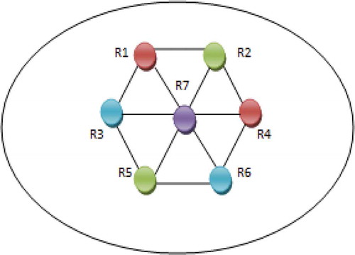
In Figure , the seven readers are colored using Graph Coloring algorithm. R1 is colored with the maroon and its adjacent readers R2 and R3 are colored with green and blue. This process is repeated until all the readers are colored based on the concept of graph coloring.
Figure 4. Time slot for colored readers.
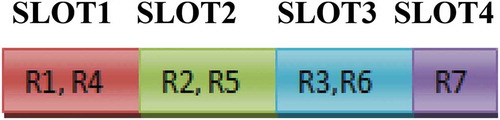
The Graph coloring-based TDMA algorithm schedules the same colored readers in the same slots as given in Figure where R1 and R4 are arranged in maroon color slot as they are in same color. Similarly, other colored readers are arranged in their respective colored slots. The energy consumption of the readers is reduced, and the readers can read the information at a faster rate.
5. Implementation of RFID-enabled supermarket
5.1. Software implementation
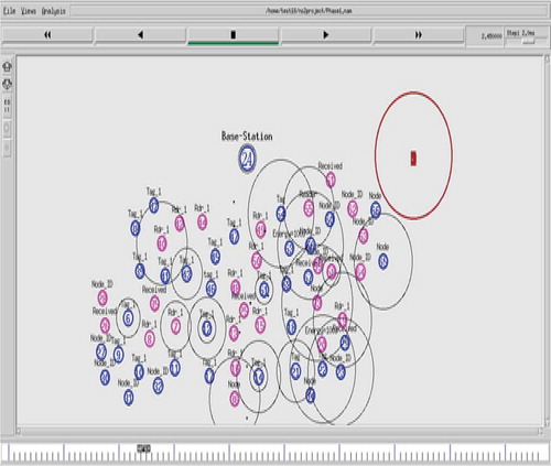
In this module, the readers, tags and base station is created using the ns2 (Network Simulator Version 2) simulator. The readers and tags thus formed were grouped as clusters, to easily detect the reader collision and to avoid the network traffic. The clustering is done to maximize the network lifetime and to achieve higher energy efficiency in the entire network. Among the several readers, one reader is chosen as a cluster head that collects the information from other readers and sends to the base station as shown in Figure . The CH is being selected for handling the connectivity of all these cluster associate nodes. The average threshold energy of the readers is calculated. The cluster head is initially elected based on the parameters like energy efficiency, the transmission and reception rate, number of tags around it, the distance between the reader to the base station and the mobility of the reader.
When the current CH loses its energy, the reader with minimum mobility whose energy level is greater than the threshold energy is chosen as the next CH within this cluster. The reader once selected as the CH, probably won’t get selected as cluster head again. The Dragonfly algorithm thereby works in identifying the other readers as cluster heads, simultaneously the process of coloring the readers also happens.
Figure 5. Cluster head selection.
The constraints for the simulation are represented in Table .
Table 1. Constraints for the simulation
5.2. Hardware implementation
Supermarket is a place where people make their purchases in order to meet their daily necessities. In earlier days and stores where RFID are not implemented, each product is scanned separately to bill it. This takes more amounts of time and energy. Also, more manpower is required for checking the products, inspecting the unbilled ones and so on.
But when RFID system comes into use, the entire billing system gets easier. The RFID system involves RFID readers and tags. Every product possesses a small tag in it, which is scanned by the mobile RFID reader to gather its details such as price, product description, quantity, and so on. In the supermarket, both customer and the sales person possess the readers. Here, an issue arises between the readers possess by customer and the sales person. In order to eliminate this issue, an effective algorithm is implemented and thereby the collisions between readers are reduced.
Figure 6. Hardware implementation of DCP.
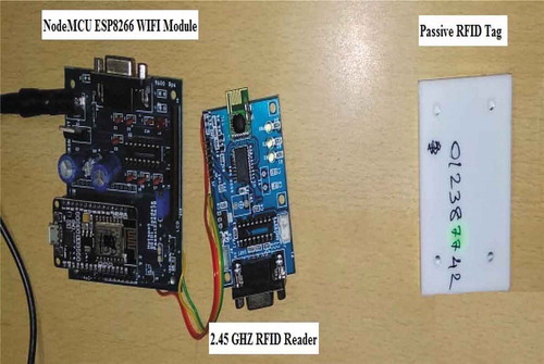
RFID implementation in real time scenario is hardware based; it can be facilitated with the help of the RFID UHF readers and passive tags as shown in Figure . It is done in such a way that the RFID reader is connected to a NodeMCU ESP8266 WIFI development board which itself is attached as a third party connectivity to the actual computer system. The hardware board possesses the components required to read the captured data by the RFID reader.
RFID reader is connected to the third party board, which is itself connected to the computer in a wired manner. There are LED light indicators to show the data transmission happening between the RFID readers and the passive tags. Once the data transfer starts, the LED Light indicators in RIFD reader blinks. To enable the RFID system, the RFID software is installed in the computer and the database file for storing the data is created. The RFID software will be configured with the details of the hardware and the data type that are being captured by the RFID reader from the respective tag.
Figure 7. The details of the data being captured by the RFID reader in the supermarket.
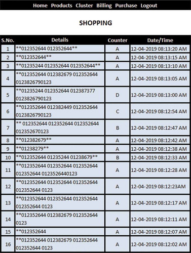
Figure contains the details of the data being captured by the RFID reader from the respective scanned tags. It contains the details such as serial no, the number of the respective tag, then the details of the RFID reader, which has actually captured that particular tag details and the time at which the data is being transferred in the RFID network. This data helps the user in facilitating the things in an easier manner with the help of the software.
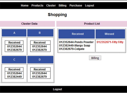
Figure shows the details regarding the tag that has been scanned, the redundant tag data and the missed tag data. The number of the tags that has got its data replicated or scanned multiple times is mentioned in the “Received” column and the tags that got its information missed are mentioned under the “Missed” column.
In this way, the entire process in RFID network is carried out. As said, the RFID reader module is connected to the computer using a hardware module; the transferred data in turn is stored into the database and analyzed.
Figure 8. Missed tag information.
6. Results and discussion
We have implemented our proposed method in the both software and hardware. There are four main factors are considered, and the data are being gathered throughout the simulation to evaluate the performance with respect to the proposed algorithm. Throughput, Identification Time delay, Percentage of Collision and Energy Consumption are the four parameters used for evaluating these protocols.
6.1. Identification time delay
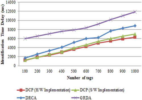
Identification time delay is a measure of the time is taken by the reader to identify any tag in the environment or within the cluster. These identifications occur within the interrogation zone as the reader cannot read the tags which lies outside this zone. This is also graphically plotted against the number of tags in that zone.
Figure represents that DCP efficiently reduces the identification time delay, especially when the number of tags are 1000, the identification time delay is increased from nearly 6500 to 7000 milliseconds in the hardware implementation. According to simulation results, it can be concluded that DCP performs better, especially in dense reader environment. In the Dragonfly Clustering Protocol, more than one reader can read the information the tags without interference from neighboring readers. So, the identification time delay is better than DRCA and GDRA protocols.
Figure 9. Graphical simulation result for identification time delay.
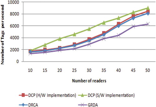
6.2. Throughput
Throughput is the measure of how fast the reader can read the data from the tags in the network, which depends on the bandwidth of readers. It is defined as the number of tags read in every second. The simulation results indicate that the throughput of Dragonfly clustering protocol is little more than hardware implementation as represented in Figure . When the number of reader reaches 50, the throughput of Dragonfly clustering protocol is 9000 tags per second during the simulation. The DRCA and GDRA protocols show less throughputs due to a high number of reader to reader and reader to tag collisions. In the proposed method, Dragonfly Clustering protocol has higher throughput than other protocols. In the GDRA protocol, the throughput decreases, as higher readers density creates reader-to-reader collisions.
Figure 10. Graphical simulation result for throughput.
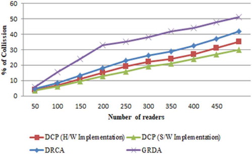
6.3. Percentage of collision (PoC)
Collision brings degradation of throughput and waste of energy, therefore excellent protocol should contribute to lesser percentage of collision. The percentage of collision (PoC) is defined by EquationEq. (4)(4)
(4) .
Dragonfly clustering protocol efficiently reduces the percentage of collision, especially when the number of reader is 500; the percentage of collision is increased from nearly 30 to 35% in the hardware implementation as represented in Figure . In the Dragonfly clustering protocol, the percentage of the collision is reduced when the density of the reader is increased compared to other protocols like DRCA and GDRA. Because in the proposed method, we implemented Dragonfly algorithm followed by Graph coloring-based TDMA scheduling algorithm to schedule all the readers in the cluster, which reads the information from the tags without the interference from neighboring readers.
Figure 11. Graphical simulation result for percentage of collision.
6.4. Energy consumption
Energy consumption compares the energy consumed by both the reader and the tag accordingly. Comparatively the energy consumed by the cluster head reader will be higher than that of the member RFID reader, since it involves in most of the data transfers, signal emissions and data reads from the tag.
Collision occurs when the signal of one reader interfere with the signal of other reader. This results in increased energy consumption of the readers. In order to overcome this problem and to stabilize the energy consumption, readers are grouped as clusters, and the Cluster Head is selected using the Dragonfly algorithm followed by Graph coloring algorithm.
Figure 12. Graphical simulation result for energy consumption.
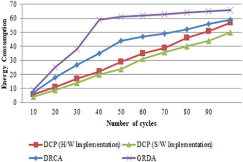
The simulation results indicate that the energy consumption of DCP is little less in software implementation than in hardware implementation as represented in Figure . When the number of cycles reaches 100, the energy consumption of Dragonfly clustering protocol is 50 Joules as measured during the simulation, while the energy consumption of DCP increases to 57 Joules during the hardware implementation. Simulation results show that DCP protocol improves the reading efficiency over 50% and meanwhile reduces power consumption dramatically. The DCP consumes less energy compared to other existing Reader anti-collision protocols like DRCA and GDRA.
7. Conclusion
The main outcome of this article is to decrease the collision occurring in the RFID network between the readers and the tags. Dragonfly-based coloring protocol is used to decrease the collisions occurring in the RFID network. If the collision is reduced, the desired stores or supermarkets might prevent themselves from incurring financial losses, which happens because of this collision. The performance of our proposed method Dragonfly based coloring protocol is evaluated in the both hardware and software based on the four parameters such as collision rate, data transmission, Identification time delay, and Energy consumption. Our proposed protocol shows better performance in the software implementation compared to hardware implementation. It also shows better performance with DCP than when compared with the DRCA and GDRA Protocols.
Additional information
Funding
Notes on contributors
C. Hema
C. Hema received the degree in computer science and engineering from Anna University in 2007. She is a research student of B.S. Abdur Rahman Crescent Institute of Science and Technology. Currently, she is an Assistant Professor (Sr.G) at B.S. Abdur Rahman Crescent Institute of Science and Technology. Her research interests are RFID, Wireless sensor networks, and she has more than 10 international journal and international conference publications to her credit.
Sharmila Sankar
Dr. Sharmila Sankar received the degree in computer science & engineering from Madras University in 2002. She received the Ph.D. degree in computer science & engineering from the Anna University in 2012. Currently, she is the Professor in Department of Computer Science and Technology at B.S.Abdur Rahman Crescent Institute of Science and Technology. Her research interests include Adhoc networks, RFID, wireless sensor networks.
M. Sandhya
Dr. Sandhya M received the degree in computer science & engineering from Madras University in 2002. She received the Ph.D. degree in computer science & engineering from the Anna University in 2012. Currently, she is the Professor in Department of Computer Science and Engineering at B.S.Abdur Rahman Crescent Institute of Science and Technology. Her research interests include Adhoc networks, RFID, wireless sensor networks.
References
- Ahmed, H. A., Salah, H., & Robert, J. (2018). Closed-form solution for aloha frame length optimizing multiple collision recovery coefficients’ reading efficiency. IEEE Systems Journal, 12(1), 1047–15. https://doi.org/10.1109/JSYST.2016.2539380
- Bueno, V., Ferrero, D., & Gandino, F. (2013). A geometric distribution reader anti-collision protocol for RFID dense reader environments. IEEE Transactions on Automation Science and Engineering, 10(2), 296–306. https://doi.org/10.1109/TASE.2012.2218101
- Golsorkhtabaramiri, M., & Issazadeh Kojid, N. (2017). A distance based RFID reader collision avoidance protocol for dense reader environments. Wireless Personal Communications, 95(2), 1781–1798. https://doi.org/10.1007/s11277-016-3918-0
- Jaballah, A., & Meddeb, A. (2017). “Algorithm for readers arrangement without collision in RFID networks”, In: Proceedings of International Conference on Parallel and Distributed Computing, Applications and Technologies, pp.316–321.
- Jiang, Y., Zhang, R., Cheng, W., & Sun, W. (2016). An efficient multi-channel reader collision avoidance protocol in RFID systems. In: Proceedings of International Conference on IEEE Wireless Communications and Networking conference.
- Liu, B., Nguyen, N., & Yeh, V. (2016). A maximum weight independent set based algorithm for reader-coverage collision avoidance arrangement in RFID networks. IEEE Sensors Journal, 16(5), 1342–1350. https://doi.org/10.1109/JSEN.2015.2498616
- Nguyen, N., Liu, B., & Pham, V. (2016). A dynamic-range based algorithm for reader-tag collision avoidance deployment in RFID networks. Proceedings of International Conference on Electronics, Information, and Communications.
- Safa, H., Hajj, W., & Meguerditchian, C. (2015). A distributed multi-channel reader anti-collision algorithm for RFID environments. Computer Communications, 64, 44–56. https://doi.org/10.1016/j.comcom.2015.01.013
- Salah, H., Ahmed, H. A., & Robert, J. (2016). Maximum likelihood decoding for non- synchronized UHF RFID tags. Proceedings of International Conference on IEEE Topical Conference on Wireless Sensors and Sensor Networks.
- Su, J., Shen, Z., & Hong, D. (2016). An effective frame breaking policy for dynamic framed slotted Aloha in RFID. IEEE Communication Letters, 20(4), 692–695. https://doi.org/10.1109/LCOMM.2016.2521839
- Su, J., Sheng, Z., & Xie, L. (2017). A collision-tolerant based anti-collision algorithm for large scale RFID system. IEEE Communication Letters, 21(7), 1517–1520. https://doi.org/10.1109/LCOMM.2017.2685590
- Tan, X., Wang, H., & F, L. (2018). Collision detection and signal recovery for UHF RFID systems. IEEE Transactions on Automation Science and Engineering, 15(1), 239–250. DOI:10.1109/TASE.2016.2614134 .
- Vales Alonso, J., Parrado Garca, F. J., & Alcaraz Osl, J. J. (2016). An optimization-based scheduler for RFID dense-reader environments. Ad Hoc Networks, 37(2), 512–525. https://doi.org/10.1016/j.adhoc.2015.10.004
- Xu, H., Shen, W., & li, P. (2017). A novel algorithm L-NCD for redundant reader elimination in P2P-RFID network. Journal of Algorithms & Computational Technology, 11(2), 135–147. https://doi.org/10.1177/1748301816688020