
 ?Mathematical formulae have been encoded as MathML and are displayed in this HTML version using MathJax in order to improve their display. Uncheck the box to turn MathJax off. This feature requires Javascript. Click on a formula to zoom.
Abstract
This article presents an indoor assistive system that addresses the challenges faced by visually impaired individuals. The proposed system helps the visually impaired individuals to move indoor and make them independent of any external assistance. The proposed system consists of a camera with a processing unit and an accompanying Time-of-Flight sensor providing an efficient, convenient and cost-effective solution. The proposed system achieves average object detection accuracy of 73.34% and a 5% error margin in detecting the distance and length of detected objects. The performance comparison with two existing systems shows that the proposed system provides a very close performance to the benchmarks with advantages of portability easy-to-use and no requirement for cloud services.
PUBLIC INTEREST STATEMENT
The visually impaired face many challenges when trying to integrate with others in public places and indoor areas. These challenges require precise solutions to overcome. Most of the available research focuses on a single point only, that enhance the life of the blind and visually impaired group. This is not efficient, as having multiple separated solutions will overwhelm the person. In this research article, a system is designed exclusively for the visually impaired, which helps them in their daily lives, in indoor areas, and makes them more comfortable and engaged with other people. The reduction of the gaps in the lives of the blind and visually impaired will have a big effect on the society and social life.
1. Introduction
The quality of life of a person is directly related to his/her interaction with surroundings. Visually impaired (VI) individuals cannot easily visualize the surrounding space, and need to touch and identify objects as they move and interact, which creates a big gap in how they perceive their surroundings.
According to World Health Organization (WHO), approximately 1.3 billion people live with some forms of vision impairment while 36 million people are completely blind (CitationBlindness and vision impairment). Although many recommendations and suggestions to reduce the causes of such phenomenon (Kartubi et al., Citation2020), the number of VI persons in the world is still rising. This wide-spread problem drives researchers to look for solutions or techniques to help the VI persons. The proposed solutions focus on how to make VI able to navigate and recognize objects indoors without the help of others. However, most of the proposed techniques suffer either from technical limitations or practicality limitations (such as non-portability, size, high power consumption and limited support). Past research work has been devoted to solve some of these limitations. However, past solutions have limited success in developing commercial portable devices that can achieve high ratio of indoor object recognition with adequate information without the need of online connection.
The structure of the article is as follows: The existing solutions and background review are presented in Section II. The used research methodology in developing the proposed system is presented in Section III. A detailed discussion of the proposed system’s structure and implementation is presented in Section IV. The setup of the testing process is introduced in Section V. In Section VI, results of the proposed system and a performance comparison with two existing powerful systems are presented in detail. Finally, the research conclusion is listed in Section VII.
2. Background review and existing solutions
There are many solutions designed for navigation and obstacle detection of VI individuals, most popular being a cane. However, less than 2% of Americans who are blind or visually impaired use a cane for orientation and mobility (CitationFacts about the visually impaired from washington state department of services for the blind). One of the newest alternative systems is the Smart Cane (Kim & Cho, Citation2013).
The smart cane is a common guidance stick, that comes with an Ultra-Sonic sensor. The sensor detects the objects and the obstacles in front of it within a preset range, and then it gives a user feedback to indicate that there is an object ahead. A major problem with the smart cane is that it does not give an absolute measured distance to the objects, so it is only useful for obstacle detection and navigation. In addition, it does not give any extra information about the objects ahead. Consequently, the preference and satisfaction rates of using a Smart Cane were low with the VI people.
Another system is made to visualize metal objects (Pedersen, Citation2020). This system uses a smartphone with additional sensors. The main objective of this system is to be able to get information about metal objects around the area. This can be helpful as it can provide some important information about the objects, for example, if the objects are metal or magnetic. But the lack of other information makes this system very limited in operation.
The use of a depth camera, for example, based on Microsoft Kinect, that detects objects and gives depth information is an interesting approach. However, the main issue of Kinect-based systems is the portability and size, as Kinect is large, heavy to carry around, and consumes a lot of power (Tenney, Citation2012).
A blind navigation system based on Kinect is proposed in a recent research (Orita et al., Citation2013). The system uses depth data from Kinect, processes it on a computer, and then outputs the data to the user as audio feedback. This system is similar to the other obstacle detection systems. The main advantage is using the powerful Kinect libraries, which reduce the workload. When the system recognizes an obstacle, it sends a voice feedback to the user.
A Kalman Filter is used for object tracking (Espejel-Garcia et al., Citation2017). The system obstacle detection is based on a novel type of windowing technique. This windowing method uses a column-based window that scans the image in a recursive pattern, and computes mean or average value of each step. This computer vision algorithm yields high accuracy results. This system is very useful in navigation scenarios. The main limitation is that this system is still indicating only the obstacles as it does not provide details about the objects.
The Kinect has high power consumption, which can be addressed using photovoltaic cells (solar panel) (Hysa, Citation2019). The solar panel can help the portability of the system by reducing the load on the battery, but the main limitation is that it needs direct sunlight and efficiency is very low.
Kinect offers the usage of Microsoft Azure Cognitive Services (CitationMicrosoft cognitive services). The ability to do all the processing on the cloud means minimizing the need for a powerful base system to process the data. But this comes at the price of necessity to be always connected. Any network interference leaves this system useless. There are other ways to do the processing locally using a Graphics core (Razian & MahvashMohammadi, Citation2017), but it requires more powerful hardware, and this will lead to a larger sized system.
Another similar system is proposed in (Yelamarthi et al., Citation2014), but with a vibrotactile feedback system. The system uses left and right vibration modules to estimate the object distance to the user. This system is a merged concept between the smart cane system and the Kinect navigation system discussed earlier. This system uses k-nearest neighbors algorithm (Altman, Citation1992), which is a non-parametric method used for classification. The input consists of the k closest training examples in the feature space. An object is classified by a vote of its neighbors, with the object being assigned to the class most common among its k nearest neighbors. With this algorithm, this system can identify fast and accurately the obstacles for real-time navigation. The idea behind the system is promising, as absence of audio feedback means that even the visually impaired with hearing impairment can still benefit from the system. In addition, there are still many users who do not like the audio output. However, this system still has the limitation of the systems reviewed above, including that it does not give more information about the object.
A research on object detection using Kinect has been performed in the past (F. Saponara Iriarte Paniagua, Citation2011), with many techniques proposed to process the image data using Kinect build-in models, for example Kalistatov (Citation2019). Though the Kinect object detection uses complex algorithms, due to its powerful processor, it can handle operations fast. In particular, the Kinect system uses the Point Cloud Library (CitationPoint cloud library (pcl)) which is an open-source library of algorithms for point cloud processing tasks supported by Kinect. The library contains algorithms for feature extraction and segmentation. This system uses this library to achieve a high accurate and fast object detection.
3. Research methodology
Motivated by the limitations of the current systems and a need to support VI individuals, the system proposed in this article has been designed with the following features:
1) Portable, offline, and low power consuming system.
2) Capable to detect objects and their distance to the user.
3) Capable to acquire various information about the objects (i.e., dimensions).
4) User-friendly input and output interfaces.
5) Independent of the physical indoor layout.
Figure 1. Research path chart.
The research path chart is shown in Figure . The first step is to find a suitable main board that can fit the features required, for example, the portability. The next step is deciding on software models for object detection and/or discovering additional features about the objects. Simultaneously, it is necessary to design an input and output methods for the system hardware. The additional hardware includes various sensors necessary to discover different features of the objects, for example, height, depth, etc. After that, the full integration between all the parts will be performed to get the prototype system. Then, the testing phase of the system starts, and results are recorded. Finally, the results are used for comparison with other available systems.
Our prior work presented in (Noman et al., Citation2019), reports a detailed comparison of the performance of two existing systems, Azure Cloud and Microsoft Kinect, used as benchmark in this study.
4. Proposed system structure and implementation
The proposed system consists of three major components shown in Figure .
Figure 2. The main system components: (1) SBC (2) CCD Camera (3) ToF sensor.
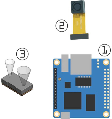
Single-Board Computer (SBC): The Single-Board Computer is responsible for reading the input and producing the output to the user.
Object Detection: The object detection consists of a CCD camera and an object detection software module.
Time-of-Flight (ToF) sensor: The Time-of-Flight sensor measures the distance to the object and the object height.
The system operation flowchart is shown in Figure . The system starts with powering up and the initialization that triggers the process that communicates with the CCD camera to get the processed image data. Then, two operations are conducted at the same time; one is the ToF sensing and the other is the object detection operation. The results of both operations are recorded and combined to produce the output to the user.
The following sections describe in detail all design components.
Figure 3. The flowchart of the system.
4.1. Single-board computer
The system requires a main base-processing board able to connect to all other system parts including the input and output units, and able to execute the high-computational image processing models. Using low-power micro-controllers as the main base board is not feasible since they have a limited processing capability. A much better choice for the main processing base unit is a single-board computer (SBC) (Pajankar, Citation2017). The SBC is a complete computer unit built on a single circuit board. It includes microprocessor, memory, input-output units and it functions as a general-purpose computer. Many available systems are using such efficient SBCs, for example, in Robot Control (Rasmussen, Citation1989) and other applications (Akash et al., Citation2015). The OrangePi Zero Plus2 (CitationOrange pi zero plus2) has a fast 1.2 GHz 64-bit quad-core CPU, with an internal storage of 8GB and 512MB RAM, small and light, power consumption under 1 W. It has Linux mainline software support with other required features for the system. This makes the OPiZP2 a perfect choice for the proposed system. The system will use this SBC with its expansion board as the main system board.
4.2. Input/output interface modules
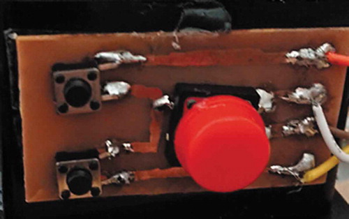
The system requires the user to initiate the start of the process as shown in the system flowchart in Figure . To achieve this, an input PCB is created. The input interface PCB is designed using Single-Pole SingleThrow (SPST) switches and is connected directly to the mainboard. The input consists of simple three keys, one main big key for selection (enter) and two-sided keys for navigation. The PCB prototype design is shown in Figure .
Figure 4. Input interface PCB.
The system has a menu formatted in a linear fashion as user interface. The user can navigate using the navigation buttons (up and down). The navigation can be done in both ways (up or down)—once the user wants to select an option he/she clicks the selection button. Figure shows the flowchart of the menu interface.
Figure 5. User interface menu: linear menu with bi-directional loop navigation.
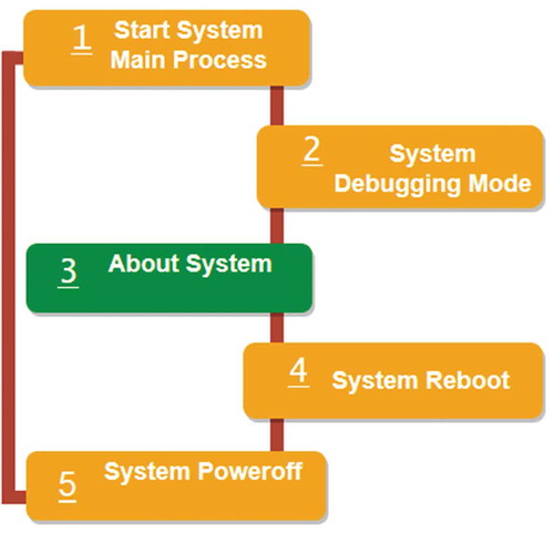
The interface has five options:
Start System Main Process: This function starts the system process to generate the final results.
System Debugging: This is debugging mode for testing and calibration.
About System: The menu showing information about the current system.
System Reboot: Restart the system.
System Power off: Powering off the system.
Providing appropriate output is a critical step in this application. The most common output method for the VI people is Braille (CitationWhat is braille?), which is a tactile writing system. Braille users can read computer screens and other electronic supports using refreshable Braille displays. However, the use of Braille cells for the output has three disadvantages:
The cost of the refreshable Braille cells is high due to the use of patented technology.
The power requirements for refreshable Braille cells is 200 V (DC) (CitationBraille cells voltage requirements).
The size and weight of refreshable Braille cells are high relative to the proposed base system.
An alternative is using an audio feedback output. As many VI individuals use voice applications and feel more comfortable with audio outputs, the system will output all the results as an audible output. The system is using a Text-to-Speech (TTS) engine (Baart & Van Heuven, Citation1990) called eSpeakNG (CitationEspeakng) to convert the results to audio. eSpeakNG is a compact, open-source, software speech synthesizer for Linux and other platforms. It uses a format synthesis method, providing many languages in a small size. To ensure a good audio quality, the system uses the standard settings for English (UK) voice. The TTS engine works together with the input PCB to create the full user interface.
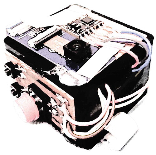
Figure 6. The proposed system prototype.
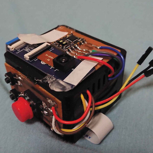
The Single-Board Computer with input/output interface prototype implementation is shown in Figure . This prototype is used with the implemented software to produce testing results.
4.3. Object detection module
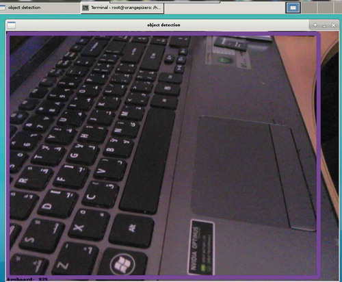
The object detection section is composed of two parts: Tensorflow and the CCD camera module. Creating accurate machine learning models capable of localizing and identifying objects in a single image remains a core challenge in computer vision. The Tensorflow Object Detection API is an open-source framework built on top of Tensorflow that makes it easy to train and use object detection models. Each model is called a Tensor. Tensorflow supports many platforms. The used platform in the proposed system is Linux-based as the choice of the SBC fits this operating system. The initial test of Tensorflow interfaced with the chosen SBC OrangePi Zero Plus2 using the default compact models proves its compatibility and its needed functionality. Figure shows the results of the object detection test using a captured image processed with the default tensor model. The object detection library displays the names of the detected objects and the estimated accuracy (as a percentage); for the example shown in Figure the result was “keyboard” with an estimated accuracy of 92%.
Figure 7. Object detection demo test on OrangePi Zero Plus2.
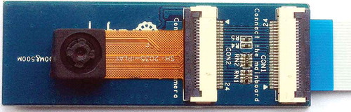
The camera module that is used with the proposed system is chosen to be GC2035. As shown in Figure , the module contains a flexible cable that help in mounting the camera easily. The camera model supports capturing RGB images up to 1600 × 1200 pixel resolution. The system CCD camera is chosen to use the resolution of 800 × 600 (0.48MP) because of faster processing time with good output accuracy.
Figure 8. CCD camera with the extension board and cable.
The Object detection process starts with the picture taken with the CCD camera, then it processes it, and finally retrieves the accuracy score from the tensor. The score is based on the accuracy output of the object detection algorithm. The system only considers scores higher than 70%, while lower scores are ignored. The output is based on the highest accuracy score of the objects detected.
4.4. Time-of-Flight (ToF) sensor
Time-of-Flight (CitationTime-of-flight) is the time that an object (or particle or electromagnetic wave) needs to travel a distance through a medium. The measurement of this time can be used as a way to measure velocity or path length or as a way to learn more about the medium. If Infrared (IR) ToF sensor is used, then the system is able to detect the absolute distance to the object.
In particular, the proposed system uses a VL53L1X ToF sensor of STMicroelectronics. The VL53L1X is small, have a detection distance of 400 mm and a programmable Region-of-Interest (ROI). The use of a changeable ROI means that the sensor is able to detect other information besides the distance, for example, height of the object. VL53L1X default Field-of-View (FOV) is 27 degrees (CitationVl53l1x datasheet), but can be reduced to 20 degrees and even further to 15 degrees. This change in FOV results in a change of the measured distance which makes the system able to calculate the height or depth of the object referring to the programmable ROI.
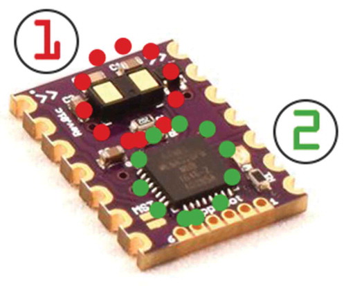
The ToF sensor is fixed at the front side of the system. The sensor is accompanied by a co-processor, i.e., a micro-controller (ATMEGA328p). This micro-controller is responsible for the sensor initialization and calibrations. The ToF sensor communicates with the mainboard by the I2C protocol. The I2C protocol uses two wires, with a speed of up to 400 kilobits per second. Figure shows the ToF sensor with its external processor.
Figure 9. ToF sensor (1) with an embedded micro-controller (2).
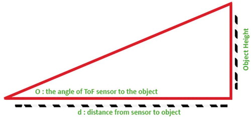
The ToF sensing process starts at the same time as object detection. The process depends on the micro-controller's initialization and readings. The ToF sensor programmable ROI gives a change in the FOV of the sensor. After reading the data with the changed ROI, a simple mathematical calculation is performed to generate the required results from the data acquired. Figure shows how the variable FoV changes the distance measured. This change can be used in calculation to get an approximate height of the object as:
where is the angle between the ToF sensor and the objects.
Figure 10. ToF sensor measurements.
The ToF process calculates and record the results. Any result that is out of range is discarded. Finally, the ToF process ends and the system will output the final ToF results after the object detection results.
5. Evaluation setup
The evaluation setup is as follows:
1) The testing room is well lit, with standard office size (8 x 10 ft).
2) The testing is done with the system prototype shown in Figure . The Tensorflow model is the standard “ssd_mobilenet_v1_coco” model, and the ToF sensor with factory default calibrations and the main system process function.
3) The results are recorded for each test. The output is listened via headphones and printed in debug mode. The time measurements are taken with an external digital time-stop clock (in seconds).
4) The object actual name is recorded as commonly known. The distance to the objects is measured perpendicularly from the system by a tape meter (in centimeters). The height of the object is measured by a ruler (in centimeters) if applicable.
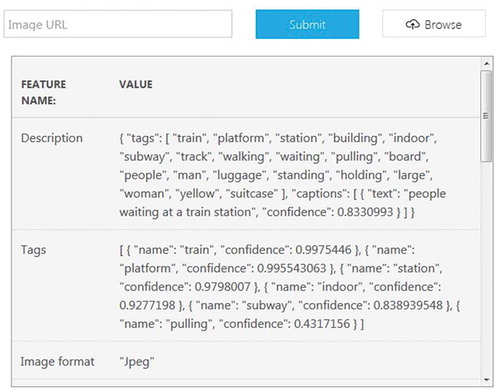
5) The same test image (.jpg) is used in Microsoft Azure Cloud Vision for bench-marking. Figure shows the results page. The cloud time measurement is ignored due to the required network connection. The Azure result is given as a tag or description, and it includes a confidence value. This value can be converted to a percentage and compared directly with the proposed system output accuracy.
Figure 11. Microsoft Azure object detection cloud interface (CitationMicrosoft azure cloud interface).
6. Results and discussion
The system is compared with two exiting systems: the Azure Cloud (online-network-based method) and Microsoft Kinect. A detailed performance study of these two existing systems can be found in (Noman et al., Citation2019).
6.1. Comparison with Azure Cloud
The Microsoft Azure Cloud provides a basic cloud server for object detection. Table shows the cloud basic server specifications (CitationMicrosoft azure hardware specifications) versus the proposed system. The cloud server has a more powerful CPU and the available RAM is 7 times of what is available in the proposed system. The main advantage of the proposed system is that it can work offline; this advantage helps to overcome any issues when there is a network interference or weak coverage. The proposed system keeps a steady performance regardless of any network loss.
Table 1. Comparison between the proposed system and Microsoft Azure Cloud
To start the testing phase, a number of images will be used with the two compared systems. The images will be captured by the described CCD camera. The testing image capture is performed by a software program, that takes a picture when a button is pressed and saves the image to the flash storage. Figure shows how the images are being taken. The focus is set to an object with a perpendicular FoV (i.e., no angles shots).
Figure 12. Testing image capture.
Three hundred test images are recorded for different objects—from large (chairs/desks/drawers) to small (keys/glasses/bottles) objects. The variety is random to ensure a fair comparison. Then, the images are passed on to the comparison systems, and their results are recorded per the setup discussed in Section V.
Figure 13. Testing Result Table 1 (Tensorflow).
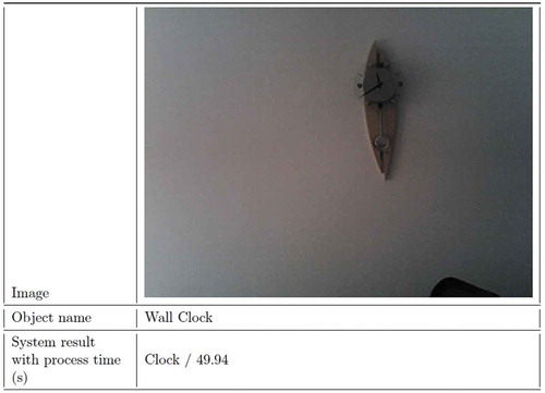
Figure 14. Testing Result 1 (Azure Cloud).
One of the test results is shown in Figure . The result table includes the image captured and processed, the name that the system outputs, and other information if applicable. This test has a “wall clock” as the object. Note that the object is not centered in the image.
The proposed system was able to detect the clock correctly. The system ignored the height calculations due to the object placements. The Azure Cloud returned “wall” as the highest result as shown in Figure . The closest result to the object is the “caption” with low confidence of 42.6%. The Azure processing focused more on the white wall, and did not give a high accurate result for the clock. On the other hand, the proposed system ignored the white background, and focused on the object only.
Figure 15. Testing Result Table 2 (Tensorflow).
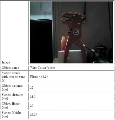
Figure 16. Testing Result 2 (Azure Cloud).
Another test is shown in Figure . This test focuses on a wire cutter or what looks like a pliers. The proposed Tensor flow-based system was able to get “Pliers” as the result. In addition, the system measured distance correctly within 5% error. The interesting part is that the approximated height is also close to the actual measurements. Figure shows the Cloud results, with the closest result being a “tool” with a low confidence of 30.1%.
Figure 17. Testing Result Table 3 (Tensorflow).
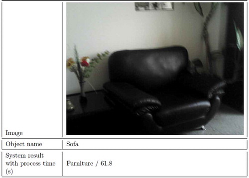
Figure 18. Testing Result 3 (Azure Cloud).
A large size object test is shown in Figure . This test object is a sofa. There are many other objects in the image frame, but the proposed system was able to get a close result which is “Furniture”. It can be considered an accurate result, but this may vary depending on the user. The result of the Azure system was more accurate, as shown in the “caption” as shown in Figure . It not only labelled the sofa as “leather chair” but also provided additional details like “living room”.
Other tests followed the same process. To get a close comparison between the average of the two systems results, a testing summary chart is created. The chart has two parameters, the number of identified objects accurately (with a high accuracy/confidence of 75% as minimum) and non-identified objects (below 75% accuracy/confidence).
The chart for both systems is shown in Figure . As the figure shows, the identified objects average detection rate is 76.67%, while the proposed system testing summary shows objects average detection rate of 73.33%.
Figure 19. Testing summaries Pie Charts.
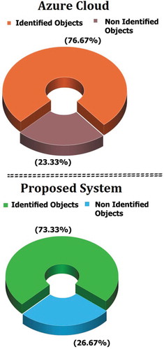
The testing summaries shown in Figure demonstrate that the average difference between Microsoft Azure Cloud and the proposed system is 3.34% (76.67%-73.33%). This small difference can be reduced further with additional training, and by increasing the testing pool.
Both object detection methods, Azure cloud-based and Tensorflow based, have limitations; one common limitation is the processing power required. The Azure cloud depends on the servers to do its work, while Tensorflow needs a local machine to do the processing. Another limitation can be the cost. The Azure Cloud, and all other Cloud services, have a subscription-based model. This means that using the Cloud processing adds up to the net cost with time. On the other hand, Tensorflow is an open-source library, and there is no maintenance cost other than the maintenance of the local system needed.
6.2. Comparison with Kinect
The Microsoft Kinect is a powerful hardware successfully used in many computer vision tasks. Though a powerful tool, the Kinect has many limitations:
The Kinect is a very bulky device, compared to the proposed system and other portable systems.
The Kinect is not lightweight.
The Kinect is power hungry, it needs at least 24 W power supply, comparing to the proposed system. That uses less than 1 W of power.
The Kinect price is almost four times the price of the whole proposed system.
The Kinect still needs another system to utilize the software functions (i.e. a Windows machine).
Kinect has been used in the past for object recognition, see, for example F. Saponara Iriarte Paniagua (Citation2011), where it is demonstrated that the Kinect object detection with standard calibrations is able to achieve 83% object detection success rate, while with advanced calibration, the detection success rate jumps to 88%.
Unlike the comparison of the proposed system with Microsoft Azure Cloud, the proposed system cannot be fairly compared to the Kinect, due to Kinect`s special CCD camera and lenses. However, based on the results reported in (F. Saponara Iriarte Paniagua, Citation2011) it can be inferred that the average difference in accuracy is approximately 10%. This comparison shows that the proposed system provides very close accuracy results to the Microsoft Kinect, while keeping other advantages over the Kinect hardware. Note that all of the proposed system testing is also performed with no advanced calibrations. This means that the difference can be reduced further by calibrating and tuning the proposed system.
Another recent research is made, using the new Azure Kinect with improved specifications and cloud support (Lee et al., Citation2019). This research shows the accuracy results across different configurations. At a steady nominal distance, the Azure Kinect have an accuracy of 85%-95%. Despite the improved results, this system shares the same limitations and drawbacks to that of the original Kinect.
The results of the direct and in-direct comparisons show that the proposed system performs close to the two available advanced exiting techniques with added important features such as portability, low cost, and off-line computing.
7. Conclusion
In this article, a new efficient system for assisting visually impaired individuals indoor is presented. The proposed system consists of a CCD camera with a processing unit and an accompanying Time-of-Flight sensor. The system is designed to be accessible and easy to use. The processing unit uses captured images to detect objects, based on object-detecting Tensorflow model. The testing of the system integration and comparison with other available systems (Microsoft Azure Cloud and Microsoft Kinect) yielded close results. The proposed system average detection accuracy is 73.34%. The difference in object detection accuracy is less than 10% compared to other two existing systems and in some cases, the detection of the proposed system outperforms their performances. The proposed system shows a 5% error margin in detecting the distance and length of detected objects. The overall comparison can benefit many other researches that want to use object detection methods. The proposed system has many advantages over the other two existing systems such as offline-use, portability, easy-to-use interface and low cost.
The proposed system still has some limitations, for example, it is still slower in processing time, and without calibrations/tuning, it can produce inaccurate results. Future studies can be made to improve the performance and reliability of the proposed system. The use of a fast processor can lead to shorter processing time, while the calibrations of the ToF sensor can give more accurate results. The training of the Tensorflow model will also boost the accuracy level. All these improvements would keep the proposed system closer to other solutions, while maintaining the advantages.
Acknowledgements
Special thanks to Mr. Auda Hazeem (CEO of Nattiq Technologies), Ms. Mayyada Diab and all Nattiq family for the support and feedback on this research project. Special appreciation and gratitude to Mr.Wessam Shehieb for his all-time support and encouragements during the time of this research project.
Additional information
Funding
Notes on contributors
Mohammed Noman
Mohammed Noman is the head of Research and Development at Nattiq Technologies, Sharjah, UAE. He has designed multiple systems and solutions for the Visually Impaired during his work-time. He has MPhil in Electronic and Electrical Engineering from the University of Strathclyde Glasgow, United Kingdom, 2019. His research interests are electronic systems and devices, hardware system design and software system design.
Vladimir Stankovic received the Dr.- Ing. (Ph.D.) degree from the University of Leipzig, Germany in 2003. His research interests include signal and information processing, graph signal processing, and explainable artificial intelligence with applications to smart homes and buildings and remote healthcare.
Ayman Tawfik is the head of the Electrical and Computer Engineering Department, Ajman University, UAE. He has PhD in Electrical Engineering from University of Victoria, Canada, 1995. His research interests are digital signal processing, digital image processing, VLSI signal processing, digital communication, internet-of-things, computer organization and education technology.
Vladimir Stankovic
Mohammed Noman is the head of Research and Development at Nattiq Technologies, Sharjah, UAE. He has designed multiple systems and solutions for the Visually Impaired during his work-time. He has MPhil in Electronic and Electrical Engineering from the University of Strathclyde Glasgow, United Kingdom, 2019. His research interests are electronic systems and devices, hardware system design and software system design.
Vladimir Stankovic received the Dr.- Ing. (Ph.D.) degree from the University of Leipzig, Germany in 2003. His research interests include signal and information processing, graph signal processing, and explainable artificial intelligence with applications to smart homes and buildings and remote healthcare.
Ayman Tawfik is the head of the Electrical and Computer Engineering Department, Ajman University, UAE. He has PhD in Electrical Engineering from University of Victoria, Canada, 1995. His research interests are digital signal processing, digital image processing, VLSI signal processing, digital communication, internet-of-things, computer organization and education technology.
Ayman Tawfik
Mohammed Noman is the head of Research and Development at Nattiq Technologies, Sharjah, UAE. He has designed multiple systems and solutions for the Visually Impaired during his work-time. He has MPhil in Electronic and Electrical Engineering from the University of Strathclyde Glasgow, United Kingdom, 2019. His research interests are electronic systems and devices, hardware system design and software system design.
Vladimir Stankovic received the Dr.- Ing. (Ph.D.) degree from the University of Leipzig, Germany in 2003. His research interests include signal and information processing, graph signal processing, and explainable artificial intelligence with applications to smart homes and buildings and remote healthcare.
Ayman Tawfik is the head of the Electrical and Computer Engineering Department, Ajman University, UAE. He has PhD in Electrical Engineering from University of Victoria, Canada, 1995. His research interests are digital signal processing, digital image processing, VLSI signal processing, digital communication, internet-of-things, computer organization and education technology.
References
- Akash, K., Kumar, M. P., Venkatesan, N., & Venkatesan, M. (2015, December). A single acting syringe pump based on raspberry pi – soc. In 2015 IEEE International Conference on Computational Intelligence and Computing Research (ICCIC), Madurai, India (pp. 1–19). https://doi.org/10.1109/ICCIC.2015.7435694.
- Altman, N. S. (1992). An introduction to kernel and nearest-neighbor nonparametric regression. The American Statistician, 46(3), 175–185. https://doi.org/10.2307/2685209
- Baart, J., & Van Heuven, V. (1990, 7). From text to speech; the mitalk system: Jonathan allen, m. sharon hunnicutt and dennis klatt (with robert c. armstrong and david pisoni): Cambridge university press, cambridge, 1987. xii+216 pp. Lingua, 81(2–3), 265–270. https://doi.org/10.1016/0024-3841(90)90014-C
- Blindness and vision impairment. Blindness and vision impairment. https://www.who.int/news-room/fact-sheets/detail/blindness-and-visual-impairment
- Braille cells voltage requirements. 200V +-5%: Absolute max. rating 215V 1.2uA typ. per dot. http://web.metec-ag.de/en/produkte-braille-module.php?p=p20
- Espeakng. Software speech synthesizer. https://github.com/espeak-ng/espeak-ng.
- Espejel-Garcia, D., Ortíz Anchondo, L., Alvarez Herrera, C., Hernandez Lopez, A., Espejel-García, V., & Villalobos, A. (2017, 12). An alternative vehicle counting tool using the kalman filter within matlab. Civil Engineering Journal, 3(11), 1029. https://doi.org/10.28991/cej-030935
- F. Saponara Iriarte Paniagua. 2011. Object recognition using the kinect. [Dissertation]. ser. Trita-CSC-E, no. 2011:115. oai:DiVA.org:kth-130762.
- Facts about the visually impaired from washington state department of services for the blind. https://dsb.wa.gov/resources/dispelling-myths.shtml
- Hysa, A. (2019, 12). Modeling and simulation of the photovoltaic cells for different values of physical and environmental parameters. Emerging Science Journal, 3(6), 395–406. https://doi.org/10.28991/esj-2019-01202
- Kalistatov, K. (2019, 5). Wireless video monitoring of the megacities transport infrastructure. Civil Engineering Journal, 5(5), 1033–1040. https://doi.org/10.28991/cej-2019-03091309
- Kartubi, N., Firmansyah, A., Pardi, P., & Budiantari, C. (2020, 3). Preparation for eye lens dose assessment at cstrm-nnea. SciMedicine Journal, 2(1), 30–37. https://doi.org/10.28991/SciMedJ-2020-0201-5
- Kim, S. Y., & Cho, K. (2013). Usability and design guidelines of smart canes for users with visual impairments. International Journal of Design, 1(7), 99–110. http://www.ijdesign.org/index.php/IJDesign/article/view/1209/559
- Lee, T. E., Tremblay, J., To, T., Cheng, J., Mosier, T., Kroemer, O., Fox, D., & Birchfield, S. (2019). Camera-to-robot pose estimation from a single image. ArXiv. abs/1911.09231.
- Microsoft azure cloud interface. Analyze an image. https://azure.microsoft.com/en-us/services/cognitive-services/computer-vision/
- Microsoft azure hardware specifications. https://blogs.msdn.microsoft.com/uk_faculty_connection/2016/09/13/quick-overview-of-azure-vm-specifications/
- Microsoft cognitive services. The cognitive services APIs harness the power of machine learning. https://azure.microsoft.com/en-us/services/cognitive-services/
- Noman, M., Stankovic, V., & Tawfik, A. E. (2019, December) Object detection techniques: Overview and performance comparison. 2019 IEEE International Symposium on Signal Processing and Information Technology (ISSPIT2019), Ajman, United Arab Emirates. https://doi.org/10.1109/ISSPIT47144.2019.9001879.
- Orange pi zero plus2. Orange Pi Zero Plus2 is for anyone who wants to start creating with technology – Not just consuming it. http://www.orangepi.org/OrangePiZeroPlus2/
- Orita, K., Takizawa, H., Aoyagi, M., Ezaki, N., & Shinji, M. (2013, December) Obstacle detection by the kinect cane system for the visually impaired. In Proceedings of the 2013 IEEE/SICE International Symposium on System Integration, Kobe, Japan (pp. 115–118). https://doi.org/10.1109/SII.2013.6776667.
- Pajankar, A. (2017, 5). Introduction to single board computers and Raspberry Pi. 1em plus 0.5em minus 0.4em Apress. (pp. 1–25). https://doi.org/10.1007/978-1-4842-2878-4_1
- Pedersen, A. (2020, 6). Altering perceptions, visualizing sub-ground metal objects. Emerging Science Journal, 4(3), 205–213. https://doi.org/10.28991/esj-2020-01224
- Point cloud library (pcl). (1989, November). https://pointclouds.org
- Rasmussen, H., “A single board computer for robot control. IEE Colloquium on Controllers for Robotic Applications - Concepts and Implementations. (pp. 5/1–5/4).
- Razian, S., & MahvashMohammadi, H. (2017, 11). Optimizing raytracing algorithm using cuda. Italian Journal of Science and Engineering, 1, 167–178. https://doi.org/10.28991/ijse-01119
- Tenney, M. (2012). Microsoft kinect – Hardware.cast technical publications series. number 10354. http://gmv.cast.uark.edu/scanning/hardware/microsoft-kinect-resourceshardware/
- Time-of-flight. The Time-of-Flight principle. https://www.terabee.com/time-of-flight-principle/
- Vl53l1x datasheet. (p. 1) https://www.st.com/resource/en/datasheet/vl53l1x.pdf
- What is braille? Method of writing words, music, and plain songs by means of dots, for use by the blind and arranged for them. http://www.afb.org/info/living-with-vision-loss/braille/hat-is-braille/123
- Yelamarthi, K., DeJong, B. P., & Laubhan, K. (2014, August). A kinect based vibrotactile feedback system to assist the visually impaired. In 2014 IEEE 57th International Midwest Symposium on Circuits and Systems (MWSCAS), College Station, TX, USA (pp. 635–638). https://doi.org/10.1109/MWSCAS.2014.6908495.