
 ?Mathematical formulae have been encoded as MathML and are displayed in this HTML version using MathJax in order to improve their display. Uncheck the box to turn MathJax off. This feature requires Javascript. Click on a formula to zoom.
Abstract
It is important to further improve the traveling performances of the moon/planetary exploration rovers. To achieve this, we investigated the grouser shape of rigid wheels for use in such rovers, focusing particularly on rectangular and trapezoidal grousers. First, simple intrusion tests were carried out using the discrete element method. Grousers having a trapezoidal cross-sectional shape exerted a “packing effect” through which particles between grousers were strongly compressed. Next, single-wheel experiments were conducted, and the results show that sinkage was suppressed by the trapezoidal-shaped grousers. In addition, it was confirmed that trapezoidal-shaped grousers exhibited a drawbar-pull equivalent to that generated by the widely used rectangular-shaped grousers. Furthermore, we performed theoretical analysis using the resistive force theory to clarify the packing effect, and the results indicate that the use of a wheel with a trapezoidal-shaped grouser could be an effective method to improve the traveling performance of a rigid wheel.
PUBLIC INTEREST STATEMENT
Terramechanics is an interdisciplinary field that deals with the interaction between the ground and vehicles and is effective for trafficability characterization. In this paper, a wheel shape for the lunar/planetary exploration rover based on terramechanics is investigated. Concretely, it is proposed to use a trapezoidal shape for the grouser, which is a protrusion on the wheel surface. The trapezoidal-shaped grouser is expected to exert a packing effect in which particles are strongly compressed between them. When this shape is applied to a wheel, there is a possibility that the trafficability can be improved by suppressing sinkage without significantly reducing the traction. This study will contribute not only to the development of rover wheels but also to the development of undercarriage for other off-road vehicles such as construction machinery and disaster response robots.
1. Introduction
In future moon and planetary exploration activities, various operations, such as the landing of landers, drilling, and sampling of soil, installation of observation equipment, and construction of bases are expected to be performed on soft ground. To realize these tasks, rovers, and robots that can move on soft ground are indispensable, and extensive research has been conducted in this domain (Arvidson et al., Citation2017; Ishigami et al., Citation2007; Johnson et al., Citation2015; Knuth et al., Citation2012; W. Li et al., Citation2013; Sutoh et al., Citation2012; Wong, Citation2012). However, the surfaces of the moon and planet are covered with fine sand called regolith (Heiken et al., Citation1991), and vehicles can easily sink and get stuck in the ground (Kobayashi et al., Citation2010). To avoid such accidents, the traveling performance of rover wheels has been improved by attaching protrusions called grousers or lugs on the surface of rover wheels. However, the cross-sectional shape of the grousers used is usually rectangular, and other shapes have not been investigated in sufficient detail.
The study of the interaction between soil and machinery is called terramechanics. Traveling performances have been investigated on a wide scale from exploration rovers to mining dump trucks considering terramechanics principles (Wong, Citation2008). The evaluation approaches for traveling performance can be primarily divided into three categories. The first approach involves experimental methods. It is possible to directly obtain the traveling characteristics by conducting physical experiments, for example, using targeted vehicles or their undercarriage. The second approach involves performing numerical analysis using the discrete-element method (DEM) (Jiang et al., Citation2014; Johnson et al., Citation2015; Knuth et al., Citation2012; W. Li et al., Citation2010; Nakashima et al., Citation2010, Citation2007; Nishiyama et al., Citation2016; Smith & Peng, Citation2013) the finite element method (Chiroux et al., Citation2005; Cueto et al., Citation2016; Fervers, Citation2004; Hambleton & Drescher, Citation2008, Citation2009; Ozaki et al., Citation2015; Ozaki & Kondo, Citation2016; Xia, Citation2011). In numerical analyses, the traveling performance can be evaluated in detail if appropriate modeling and discretization are carried out as it is possible to track the interaction of the traveling part and deformable soil with high accuracy. The third approach is based on a semi-empirical theoretical formula known as the terramechanics theory (Ishigami et al., Citation2007; Senatore & Iagnemma, Citation2014; Sutoh et al., Citation2012; Wong, Citation2008, Citation2012; Zhou et al., Citation2014). The terramechanics theory predicts the traveling performance of off-road vehicles using plate intrusion tests and direct shear tests and is also used in multibody dynamics analysis (Arvidson et al., Citation2017; Ishigami et al., Citation2007; Ozaki et al., Citation2016; Zhou et al., Citation2014).
Terramechanics-based studies on grousers have been conducted focusing mainly on crawler vehicles (Muro, Citation1993; Sutoh et al., Citation2012; Yong et al., Citation2012). Yong et al. (Citation2012) investigated the influence of grouser height and interval on the driving force. They found that the grouser interval contributes significantly to the generation of the driving force, and a certain ratio of the grouser interval to the grouser height corresponds to the highest thrust. In addition, Muro (Citation1993) measured the driving force under various grouser intervals to grouser height ratios and found that the maximum thrust is generated when the ratio is in the range of 3–4. Several studies have also been conducted on wheel vehicles. For example, Yang et al. (Yang, Sun, Ma et al., Citation2014) measured lug–soil interaction forces of actively actuated lug. In addition, Yang et al. (Yang, Sun, Ma et al., Citation2014) developed a new form of wheel equipped with an actively actuated lug (ALW). They showed that ALW can improve drawbar performance in the traveling experiment of the wheel. However, most previous studies simply considered the cross-sectional shape of the grouser to be rectangular, and only a few studies focused on the evaluation of different grouser shapes.
In this study, we examined the grouser shape of rigid wheels based on all the three approaches mentioned above, namely using a simple DEM analysis, single-wheel experiments, and terramechanics theory. Specifically, we compared the traveling performance of wheels employing rectangular-shaped and trapezoidal-shaped grousers. We verified the effectiveness of the packing effect demonstrated by trapezoidal-shaped grousers, in which soil is strongly compacted between grousers during traveling, as a new concept for wheel design. In terms of terramechanics theory, we adopted the resistive force theory (RFT) (Askari & Kamrin, Citation2016; C. Li et al., Citation2013; Slonaker et al., Citation2017; Suzuki et al., Citation2019; Suzuki & Ozaki, Citation2020), which has attracted attention in recent years. The RFT can be employed to evaluate the resistive stress generated in an arbitrarily shaped object moving in granular media at a low calculation cost. Therefore, the existence of the packing effect and its effectiveness can be logically verified using the difference between the drawbar-pulls obtained from single-wheel experiments and RFT.
2. Packing effect
2.1. Basic concept of packing effect
In this study, we have focussed on the effectiveness of the trapezoidal-shaped grouser, which has not yet been investigated in existing studies. It is considered that trapezoidal-shaped grousers exhibit packing effect owing to soil compaction between the grousers during motion, which serves to improve the traveling performance. A direct effect of this approach is that the normal stress under the rigid wheel becomes large, and the sinkage of the wheel is also suppressed.
In the conventional terramechanics theory, the Coulomb’s failure criterion defined in EquationEquation (1)(1)
(1) is widely used, and traction force is mainly exerted by the shear stress
generated under the wheel, that is
where and
denote the cohesion and internal friction angle, respectively. The distribution of normal stress
is evaluated according to the vertical load and slippage of the wheel, and subsequently, the distribution of shear stress
can be evaluated using EquationEquation (1)
(1)
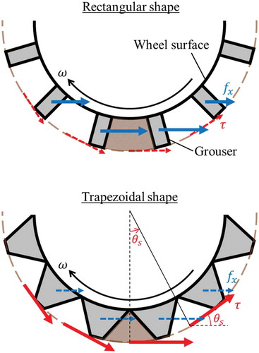
(1) . Further, the driving force of the grouser wheel is generated not only by the shear stress but also by the resistive force generated by the paddling of grousers. Assuming a simple superposition, the drawbar-pull
can be defined as follows:
is the traveling resistance,
is the force exerted by the shear stress, and
is the sum of the resistive forces of
grousers in the
direction (see Figure ).
A rectangular-shaped grouser has been traditionally adapted to maximize the second term in EquationEquation (2)(2)
(2) because conventional terramechanics theory does not take into account the change in the soil density between grousers. However, in trapezoidal-shaped grousers, the presence of packing effect can increase the normal stress
between the grousers and suppress the sinkage of the wheel. As a result, the traveling resistance
is also considered decreasing. Furthermore, from EquationEquations (1
(1)
(1) ) and (Equation3
(3)
(3) ), it is expected that the first term of EquationEquation (2)
(2)
(2) increases, and optimization of the tradeoff relationship between
,
, and
can result in a high traveling performance.
Figure 1. Schematic of driving force of grouser wheels: (a) rectangular and (b) trapezoidal grousers
2.2. DEM analysis
A simple intrusion analysis was performed using DEM to confirm the presence of the packing effect when trapezoidal-shaped grousers are used. In this study, the commercial software package Rocky DEM was used.
Figure shows the analysis models corresponding to one period of trapezoidal- and rectangular-shaped grousers. Here, to extract the packing effect, the horizontal movement of particles was suppressed on the four side surfaces of the soil boundaries.
The dimensions of rigid intruding objects reflected in the wheel grousers, as described later, and the diameter of the particles were set according to the cumulative probability as shown in Table . After configuring the soil particles, objects were set to vertically penetrate at a rate of 10 mm/s. In this study, the loose deposition condition was realized by incorporating the free falling of particles from above. The density of particle media was . Table lists the parameters used in the DEM analysis.
Table 1. The particle size distribution of the DEM analysis model
Table 2. Parameters for DEM analysis
Figure shows the relationship between the vertical reaction force and intrusion, where the intrusion is the length of the grouser tip penetrating from the initial soil surface. The figure also shows the variations in the volume fraction, obtained by dividing the particle volume filled between grousers by the space volume between grousers. The vertical reaction force of the trapezoidal grouser is larger than that of the rectangular groove for the same intrusion. This occurs as the increase in the volume fraction of the filling particles for the trapezoidal shape is quicker than that for the rectangular shape and causes larger compaction with a smaller intrusion. The beginning of compaction corresponds to the inflection point of the volume fraction.
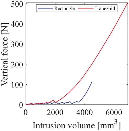
Notably, in Figure , the intrusion volumes (volume of the grouser that penetrated the initial soil surface) of the objects are different, while the intrusions are equal. Therefore, as shown in Figure , we arranged the relationship between the vertical reaction force and intrusion volume. Here, the intrusion volume was evaluated based on the surface of particle media before deformation. It is confirmed from the figure that a higher penetration resistance occurs in the trapezoidal shape even in the same intrusion volume. That is, despite the low intrusion volume, the trapezoidal-shaped grouser exhibits a higher reaction force compared to that of the rectangular type, indicating that high compaction of particle media is generated.
Thus, it can be hypothesized that the trapezoidal-shaped grouser exhibits a packing effect during motion based on the above DEM analysis results.
Figure 2. DEM analysis model corresponding to one period of the grousers
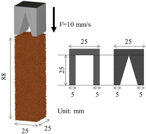
Figure 3. Variation in the vertical reaction force and volume fraction with the vertical displacement
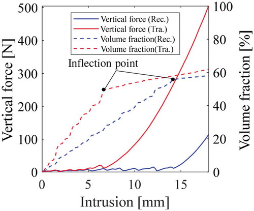
Figure 4. Variation in the vertical reaction force with intrusion volume
3. Single-wheel experiment
A single-wheel traveling experiment was conducted using grouser wheels to obtain the traveling performance corresponding to each considered grouser shape.
3.1. Experimental setup
Figure shows an overview of the experimental rig. A soil vessel made of acrylic resin, with length, width, and height of 1500 mm, 400 mm, and 400 mm, respectively, was filled with the prescribed amount of sand, and a single-wheel traveled on it. The testbed comprised both a conveyance unit and a wheel-driving unit, and each can be driven by an independent motor. The translational velocity and angular velocity of the wheel were calculated based on data obtained using encoders mounted on the conveyance motor and wheel-driving motor. Thus, by controlling the translation velocity and the angular velocity of the wheel, an arbitrary slippage can be defined.
In this study, slippage is defined by the following equation:
where the radius pertaining to the angular velocity is obtained by adding the radius, of the wheel and the grouser height,
. In this study, we conducted forced-slip experiments for four different grouser wheel types, and the slippage was controlled by fixing the angular velocity,
as 0.2 rad/s and varying the translational velocity,
. Further, the vertical load condition examined in this study is large enough to prevent a walking phenomenon of the grouser wheel.
The forces and torques generated by the wheel locomotion were measured using a six-axis force/torque sensor. Further, the wheel sinkage and traveling distance was measured using magnetic scales. The specifications of the sensors are listed in Table . The rated load of the force sensor is 200 N, while its detection sensitivity is 28–36 LSB/N. The accuracy of the magnetic scale is (80 + 15
m/m
) using the scale length
.
Table 3. Specifications of sensors
In the experiment, the vessel of the single-wheel testbed was filled with Toyoura sand. The soil density was maintained at approximately 1,488 in each traveling test. Figure show images of the four types of grouser wheels. The grousers attached to the wheels were fabricated using a 3D printer. The resin material was Accura SL7870.
The dimensions of the wheels are listed in Table . The numbers of grousers were 12 and 18. The wheel specifications were determined according to previous studies (Johnson et al., Citation2015; Ozaki et al., Citation2015; Zhou et al., Citation2014). The same thickness was used at the tip of the grousers, for the four types of wheels. Note that the evaluation of the effect of grouser thickness is beyond the scope of this study.
Figure 5. Experimental setup of single-wheel traveling apparatus. In the experiment, the translation and angular velocities were controlled under constant wheel load
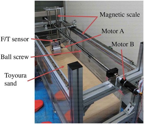
Figure 6. Grouser wheels utilized in this study
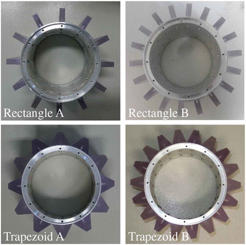
Table 4. Specifications of wheels
3.2. Experimental results
In this study, we conducted experiments at slippage values of 0.0, 0.1, 0.3, 0.5, and 0.7. Measurements were conducted 3 times at each slippage condition. Figures and 8(a show the variations in the drawbar-pull as a function of the traveling distance, whereas the results for sinkage are shown in Figures and 8(b. In all the conditions examined, the drawbar-pull in the steady rolling state tends to increase as the slippage increased, and then tends to saturate at larger slippage values. Further, it was confirmed that the trend of increase in sinkage corresponding to slippage is the same in all conditions because the shearing action of the sand by grousers per unit traveling distance increased with slippage, whereas the traveling resistance and contact area increased with sinkage. The trends obtained in the present experiment agree with those reported in the study by Sutoh et al. (Citation2012).
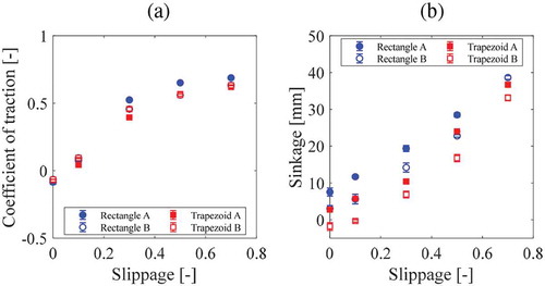
Figure shows the steady-state values of the coefficient of traction and sinkage against slippage, respectively. The coefficient of traction was computed by dividing the drawbar-pull by a constant wheel load. From the figures, it can be confirmed that the steady-state coefficient of traction is slightly lower for trapezoidal-shaped grousers, but the difference between the two cases is insignificant. On the other hand, it can be confirmed that on average, the sinkage of trapezoidal-shaped grousers is suppressed by 30% in wheels with 12 grousers and by 35% in wheels with 18 grousers compared to those of rectangular grousers.
These results indicate that a trapezoidal-shaped grouser can exhibit traction similar to or slightly lower than that of rectangular grousers while suppressing sinkage. This implies that a trapezoidal-shaped grouser can travel while preventing sinking—which is the factor responsible for making wheels become stuck—thereby enhancing the traveling performance.
Figure 7. Variations in drawbar-pull and sinkage with traveling distance for wheels with 12 grousers (Rectangle A and Trapezoid A): (a) Drawbar-pull, (b) Sinkage
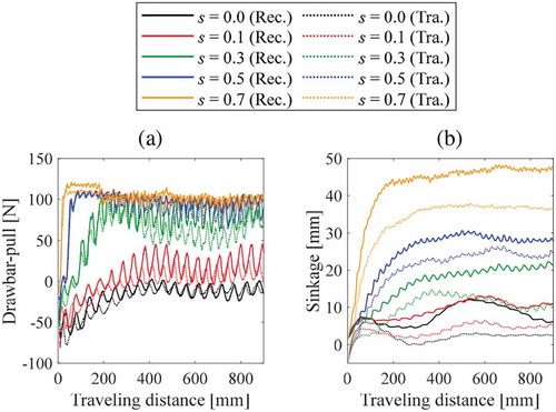
Figure 8. Variations in drawbar-pull and sinkage with traveling distance for wheels with 18 grousers (Rectangle B and Trapezoid B): (a) Drawbar-pull, (b) Sinkage
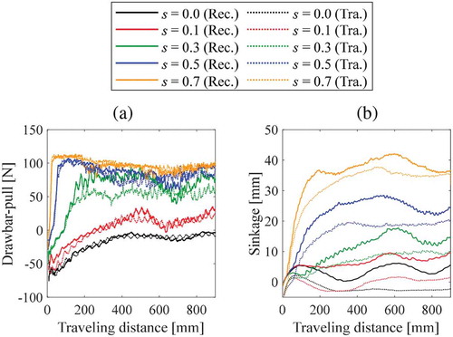
Figure 9. Relationship between traveling performance and slippage obtained through experiment: (a) Coefficient of traction, (b) Sinkage. Each plot is evaluated by the average value of steady rolling state
4. Trafficability analysis based on terramechanics theory
We performed trafficability analysis using the terramechanics theory to verify the hypothesized effects of the packing effect demonstrated by trapezoidal-shaped grouser. In this section, the principle of the RFT is first described, which is one of the terramechanics theories, and its application to traveling analyses of the four types of grouser wheels is subsequently described.
4.1. Resistive force theory (RFT)
The Bekker–Wong–Reece model (Ishigami et al., Citation2007; Senatore & Iagnemma, Citation2014; Sutoh et al., Citation2012; Zhou et al., Citation2014), which is a representative terramechanics theory, cannot be easily applied to an underbody with a complicated shape. Although it is difficult to consider the movement and shearing of soil (Suzuki et al., Citation2019), the RFT can be employed to evaluate the resistive force generated in an object with an arbitrary shape and motion at a low calculation cost. It has been demonstrated that the RFT is suitable for traveling analysis of a legged mobile robot (C. Li et al., Citation2013), and it has also been applied to evaluate the force generated in grouser wheels (Suzuki et al., Citation2019).
According to the RFT, the stress on an object (small plate) is proportional to the sinkage
, and can be defined as follows:
where subscripts and
represent the coordinate axes, as shown in Figure . The stiffness,
of the granular media, depends on the orientation angle,
of the plate, and the velocity vector angle (intrusion/extrusion angle),
. The relationship between
,
, and
can be obtained from the plate intrusion/extrusion test of the target granular media (C. Li et al., 2013). Note that the definitions of
,
, and
vary depending on whether the
component of the velocity vector is positive or negative, as shown in Figure . The distributions of
can be expressed as follows:
where the coefficients ,
,
, and
are obtained by Fourier transformation. The values of the Fourier coefficients used in this study were obtained from the study by Li et al. (2013), as listed in Table .
is the scale factor, which is used to express the stiffness of the granular media. The scale factor is a constant that depends on the granular media and can be obtained from the following relationship:
Table 5. Fourier coefficients for RFT calculation (C. Li et al., 2013)
EquationEquation (8)(8)
(8) corresponds to the vertical intrusion test when the plate orientation is horizontal.
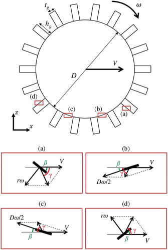
The method of applying the RFT to wheel traveling analysis can be summarized as follows:
) The wheel surface is discretized into small sections and the values of
and
) By substituting
) The drawbar-pull and wheel load corresponding to the horizontal and vertical forces are calculated by performing area integration of the resistive force of small piece-wise sections. Meanwhile, the sinkage
EquationEquation (7)(7)
(7) is an essence of low-cost calculation of RFT and it can be applied to an object with an arbitrary shape and motion; its constants are derived based on the result of the plate intrusion/extrusion test. Therefore, ingenuity is required to apply RFT to a closed shape, such as a wheel. For instance, a negative vertical stress calculated on the wheel parts (extrusion case) corresponds to the force acting on the inside of the wheel. However, this situation is different from the actual phenomenon because there is no granular medium inside a closed-shape wheel. Therefore, in this study, we assumed that no stress is generated on the wheel surface (rear area in the traveling direction) where the vertical stress becomes negative. In addition, the distribution maps of
and
correspond to the range
,
and the definitions in Figure ). Therefore, when the velocity vector,
at the calculation points, is in the positive direction of the
-axis, it is necessary to change the calculation method to apply RFT within the distribution map range. In this study, when the horizontal component of the velocity vector was inverted, as shown in Figure ), the reference plane defining
and
was also reversed. Thus, the sign of the resistive force calculated using the RFT in the horizontal direction was also reversed (Suzuki et al., Citation2019).
Figure 10. Definition of orientation angle , velocity vector angle
, and stresses
and
: (a) Definition when the
component of the velocity vector
is negative, (b) Definition when the
component of the velocity vector
is positive.
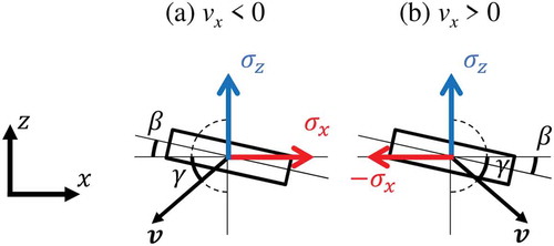
Figure 11. Application of the RFT to the wheel with grousers. The distance from the center of the wheel to the grouser surface is in the range of
4.2. Analysis results and discussion
Traveling analysis was performed based on the RFT under the conditions assumed for the single-wheel traveling experiment described in Section 3 (that is, under a constant wheel load and forced-slip condition). As presented in Table , the dimensions of the wheels were the same as those in the experiment (see Figure ). The scale factor was set as 1.5
based on a linear approximation of the plate intrusion test using the same soil condition as the single-wheel experiment. The grouser part was discretized using 30 plates, whereas the wheel part was discretized considering intervals of 0.01 rad.
Figure shows the variations in drawbar-pull with the traveling distance obtained from RFT analysis. It can be observed from the figure that the drawbar-pull fluctuates owing to the influence of the grousers. Figure also shows the results obtained using RFT analysis, in which the lines correspond to the average coefficient of traction in steady-state for each slippage. From the figure, it can be confirmed that the coefficient of traction increases with an increase in the slippage under all conditions. The RFT is based on the principle of superposition and does not take into account the influence of the grouser interval (Suzuki et al., Citation2019). Therefore, a higher number of grousers increase the drawbar-pull. Meanwhile, a comparison of the coefficient of traction for each wheel shape indicates that there is no significant difference in the values for rectangular-shaped grousers. However, the values for trapezoidal-shaped grousers were lower than those of rectangular-shaped grousers, particularly at higher slippage because the shape of the grousers affects the resistive stress distribution.
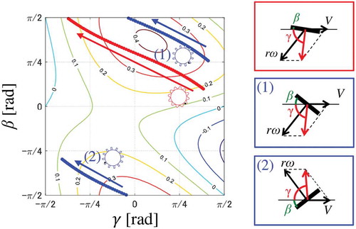
To carry out a more detailed investigation, we created trajectories of for the motion of a wheel on the stiffness distribution map. Figures and 1 show the trajectory made by two grouser wheels at slippage values of 0.1 and 0.5, respectively. In this case, we adopted rectangular wheel A and trapezoidal wheel A (see Figure ), and the values of
correspond to the midpoint of the grousers as indicated by the black dots in the figure. The trajectory of
is plotted with
and
using solid circles when
and
follow the definition in Figure (a), whereas hollow circles are used when the parameters follow the definition in Figure ). Note that when
and
exhibit discontinuous behavior, the order of their transitions is indicated in the figure by numbers (1) and (2).
As shown in Figure , when the slippage is 0.1, and
follow the definition in Figure for any considered wheel. The trajectory of the rectangular-shaped grouser seems to shift from (1) to (2) after
reaches
(i.e., the plate is vertical). In contrast, in the case of the trapezoidal-shaped grouser, the grouser is lifted from the ground before
inverts, and the trajectories are continuous. This is because the inclination of the trapezoidal grouser offsets
in a positive direction.
Furthermore, as shown in Figure , the behavior is the same as the previous one (i.e., the trajectory shifts from (1) to (2)) in which reverses only in the case of the rectangular-shaped grouser, even for slippage of 0.5. However, it can be observed that
and
follow the definition in Figure in both wheels (rectangular A and trapezoidal A) because the translational velocity decreases with an increase in the slippage, such that the velocity vector,
faces the rear side. Notably, the integration of
over the trajectory in the case of the rectangular-shaped grouser is larger than that of the trapezoidal-shaped grouser. Therefore, the drawbar-pull of the rectangular-shaped grouser is high in the high slippage regime.
It should be noted that compaction and movement (shearing) of soil are not taken into consideration in the RFT. Therefore, the results shown in Figure reflect only the resistive force of the grouser in the soil; details of these are shown in Figures and 1. In the analysis results obtained using RFT, it was predicted that the drawbar-pull drastically reduces in trapezoidal-shaped grousers than in rectangular-shaped grousers. Therefore, if there is no packing effect, the drawbar-pull in the experimental results shown in Figure should also be considerably lower when trapezoidal-shaped grousers are used. However, the fact that a decrease in the drawbar-pull of the trapezoidal-shaped grouser is smaller and the sinkage is suppressed demonstrates, paradoxically, the existence of the packing effect. Thus, the hypothesized effects of the packing effect owing to the use of trapezoidal-shaped grousers is verified using the three terramechanics approaches, namely, the DEM analysis, wheel experiment, and terramechanics theory.
Finally, we believe that a novel design taking the packing effect of a grouser wheel into consideration can be realized by rationally optimizing the shape and number of trapezoidal-shaped grousers based on several terramechanics approaches.
Figure 12. Variation of drawbar-pull with traveling distance under different slippage conditions:(a),(b)
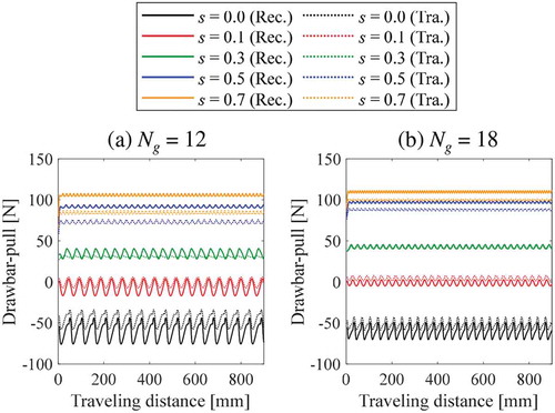
Figure 13. Relationship between coefficient of traction and slippage obtained through RFT analysis
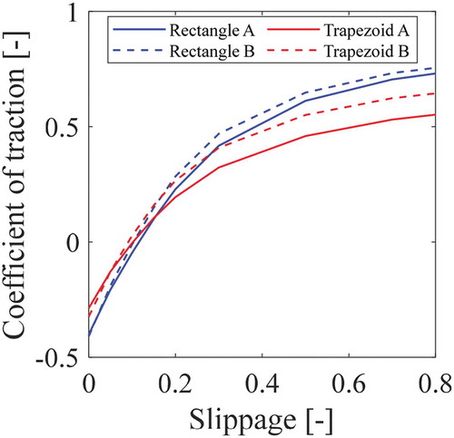
Figure 14. Trajectories of during traveling on stiffness distribution map shown in Figure (
= 0.1).
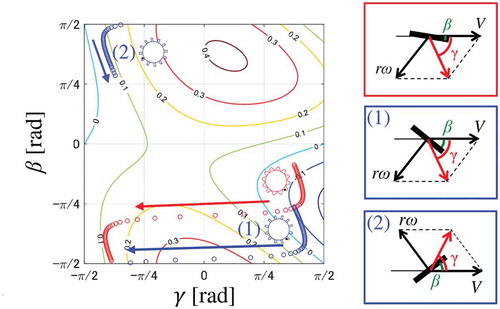
Figure 15. Trajectories of during traveling on stiffness distribution map shown in Figure (
= 0.5).
5. Conclusion
In this study, we investigated the effect of grouser shape on the traveling performance of a rigid wheel. First, an intrusion test corresponding to part of the wheel was conducted using DEM to verify the existence of the packing effect when trapezoidal-shaped grousers are used. It was confirmed that the particles between trapezoidal grousers were strongly compressed. Next, single-wheel traveling experiments were conducted to determine the traveling performance of four types of grouser wheels. The results show that the difference in the drawbar-pull between rectangular-shaped and trapezoidal-shaped grousers was minimal, and sinkage was suppressed when the trapezoidal-shaped grouser was used. In addition, traveling analysis was performed using the RFT to verify that improvement in the traveling performance is as a result of the packing effect owing to the use of the trapezoidal-shaped grouser. A comparative analysis of the two grouser shapes indicates that the drawbar-pull exerted by the trapezoidal-shaped grouser was considerably lower than that of the rectangular-shaped grouser. The difference in the results obtained from experiments and RFT analysis, paradoxically, suggests that the drawbar-pull is improved owing to the packing effect as the packing effect is not considered in the RFT. Therefore, the use of the trapezoidal-shaped grouser can be an effective approach to improve the traveling performance of a rigid wheel. In this study, however, the cross-sectional area of the trapezoidal grouser is much larger than that of the rectangular grouser. Therefore, it is also considered that the high packing density is a result of the larger intrusion volume. Therefore, it is necessary to conduct additional experiments in which the intrusion volume is the same for each wheel to verify the effectiveness of a trapezoidal grouser.
We plan to optimize the proposed shape in the future. In subsequent optimization, we will focus not only on the shape but also the height and interval of the grousers using several terramechanics approaches. In addition, we plan to investigate when the packing effect effectively occurs, because it is also important for optimization. Furthermore, we believe that the tradeoff relationship between straight trafficability and turning performance should be further investigated.
Acknowledgements
This work was supported by the Impulsing Paradigm Change through Disruptive Technologies Program (ImPACT), tough Robotics Challenge (TRC), JST, Japan. Moreover, we would like to thank Editage (www.editage.com) for English language editing.
Additional information
Funding
Notes on contributors
Hirotaka Suzuki
Hirotaka Suzuki is PhD candidate for the upcoming year at Department of Mechanical Engineering at Yokohama National University. His specialty is to evaluate the interaction between terrain surfaces and machines, and is the related numerical analyses.
Yutaro Watanabe is a master student at the Department of Mechanical Engineering at Yokohama National University. He is working on DEM analysis of granular media and its application to traveling of lunar/planetary exploration rover.
Taizo Kobayashi is the Professor at Department of Civil Engineering at Ritsumeikan University, Japan. His areas of expertise range from automation of construction work to lunar/planetary exploration.
Karl Iagnemma is President and CEO of Motional, and is co-founder of nuTonomy. As former Director of the Robotic Mobility Group at the Massachusetts Institute of Technology, he has published many technical papers related to terramechanics.
Shingo Ozaki is currently the Associate Professor at Department of Mechanical Engineering at Yokohama National University. His research area covers the computational mechanics of solids and tribology.
References
- Arvidson, R. E., Iagnemma, K. D., Maimone, M., Fraeman, A. A., Zhou, F., Heverly, M. C. (2017). Mars science laboratory curiosity rover megaripple crossings up to sol 710 in gale crater. Journal of Field Robotics, 34(3), 495–18. https://doi.org/10.1002/rob.21647
- Askari, H., & Kamrin, K. (2016). Intrusion rheology in grains and other flowable materials. Nature Materials, 15(12), 1274–1279. https://doi.org/10.1038/nmat4727
- Chiroux, R., Foster, W., Jr, Johnson, C., Shoop, S., & Raper, R. (2005). Three-dimensional finite element analysis of soil interaction with a rigid wheel. Applied Mathematics and Computation, 162(2), 707–722. https://doi.org/10.1016/j.amc.2004.01.013
- Cueto, O. G., Coronel, C. E. I., Bravo, E. L., Morfa, C. A. R., & Suárez, M. H. (2016). Modelling in fem the soil pressures distribution caused by a tyre on a rhodic ferralsol soil. Journal of Terramechanics, 63, 61–67. https://doi.org/10.1016/j.jterra.2015.09.003
- Fervers, C. (2004). Improved fem simulation model for tire–soil interaction. Journal of Terramechanics, 41(2–3), 87–100. https://doi.org/10.1016/j.jterra.2004.02.012
- Hambleton, J., & Drescher, A. (2008). Modeling wheel-induced rutting in soils: Indentation. Journal of Terramechanics, 45(6), 201–211. https://doi.org/10.1016/j.jterra.2008.11.001
- Hambleton, J., & Drescher, A. (2009). Modeling wheel-induced rutting in soils: Rolling. Journal of Terramechanics, 46(2), 35–47. https://doi.org/10.1016/j.jterra.2009.02.003
- Heiken, G. H., Vaniman, D. T., & French, B. M. (1991). Lunar sourcebook-a user’s guide to the moon. Research supported by NASA, Cambridge, England, Cambridge University Press, 1991, 753. No individual items are abstracted in this volume.
- Ishigami, G., Miwa, A., Nagatani, K., & Yoshida, K. (2007). Terramechanics-based model for steering maneuver of planetary exploration rovers on loose soil. Journal of Field Robotics, 24(3), 233–250. https://doi.org/10.1002/rob.20187
- Jiang, M., Liu, F., Shen, Z., & Zheng, M. (2014). Distinct element simulation of lugged wheel performance under extraterrestrial environmental effects. Acta Astronautica, 99, 37–51. https://doi.org/10.1016/j.actaastro.2014.02.011
- Johnson, J. B., Kulchitsky, A. V., Duvoy, P., Iagnemma, K., Senatore, C., Arvidson, R. E., & Moore, J. (2015). Discrete element method simulations of mars exploration rover wheel performance. Journal of Terramechanics, 62, 31–40. https://doi.org/10.1016/j.jterra.2015.02.004
- Knuth, M. A., Johnson, J., Hopkins, M., Sullivan, R., & Moore, J. (2012). Discrete element modeling of a mars exploration rover wheel in granular material. Journal of Terramechanics, 49(1), 27–36. https://doi.org/10.1016/j.jterra.2011.09.003
- Kobayashi, T., Fujiwara, Y., Yamakawa, J., Yasufuku, N., & Omine, K. (2010). Mobility performance of a rigid wheel in low gravity environments. Journal of Terramechanics, 47(4), 261–274. https://doi.org/10.1016/j.jterra.2009.12.001
- Li, C., Zhang, T., & Goldman, D. I. (2013). A terradynamics of legged locomotion on granular media. science, 339(6126), 1408–1412. https://doi.org/10.1126/science.1229163
- Li, W., Ding, L., Gao, H., Deng, Z., & Li, N. (2013). Rostdyn: Rover simulation based on terramechanics and dynamics. Journal of Terramechanics, 50(3), 199–210. https://doi.org/10.1016/j.jterra.2013.04.003
- Li, W., Huang, Y., Cui, Y., Dong, S., & Wang, J. (2010). Trafficability analysis of lunar mare terrain by means of the discrete element method for wheeled rover locomotion. Journal of Terramechanics, 47(3), 161–172. https://doi.org/10.1016/j.jterra.2009.09.002
- Muro, T. (1993). Terramechanics. In Gihodo shuppan, in Japanese (pp. 1–235).
- Nakashima, H., Fujii, H., Oida, A., Momozu, M., Kanamori, H., Aoki, S., Yokoyama, T., Shimizu, H., Miyasaka, J., & Ohdoi, K. (2010). Discrete element method analysis of single wheel performance for a small lunar rover on sloped terrain. Journal of Terramechanics, 47(5), 307–321. https://doi.org/10.1016/j.jterra.2010.04.001
- Nakashima, H., Fujii, H., Oida, A., Momozu, M., Kawase, Y., Kanamori, H., Aoki, S., & Yokoyama, T. (2007). Parametric analysis of lugged wheel performance for a lunar microrover by means of dem. Journal of Terramechanics, 44(2), 153–162. https://doi.org/10.1016/j.jterra.2005.11.001
- Nishiyama, K., Nakashima, H., Yoshida, T., Ono, T., Shimizu, H., Miyasaka, J., & Ohdoi, K. (2016). 2d fe–dem analysis of tractive performance of an elastic wheel for planetary rovers. Journal of Terramechanics, 64, 23–35. https://doi.org/10.1016/j.jterra.2015.12.004
- Ozaki, S., Hinata, K., Senatore, C., & Iagnemma, K. (2015). Finite element analysis of periodic ripple formation under rigid wheels. Journal of Terramechanics, 61, 11–22. https://doi.org/10.1016/j.jterra.2015.06.003
- Ozaki, S., & Kondo, W. (2016). Finite element analysis of tire traveling performance using anisotropic frictional interaction model. Journal of Terramechanics, 64, 1–9. https://doi.org/10.1016/j.jterra.2015.12.001
- Ozaki, S., Suzuki, H., Kondo, S., & Uematsu, K. (2016). Fem-based terramechancis analysis of tire traveling on multi-layered ground. In Proceedings of the 8th Americas Regional Conference of The ISTVS, Detroit, USA.
- Senatore, C., & Iagnemma, K. (2014). Analysis of stress distributions under lightweight wheeled vehicles. Journal of Terramechanics, 51, 1–17. https://doi.org/10.1016/j.jterra.2013.10.003
- Slonaker, J., Motley, D. C., Zhang, Q., Townsend, S., Senatore, C., Iagnemma, K., & Kamrin, K. (2017). General scaling relations for locomotion in granular media. Physical Review E, 95(5), 052901. https://doi.org/10.1103/PhysRevE.95.052901
- Smith, W., & Peng, H. (2013). Modeling of wheel–soil interaction over rough terrain using the discrete element method. Journal of Terramechanics, 50(5–6), 277–287. https://doi.org/10.1016/j.jterra.2013.09.002
- Sutoh, M., Yusa, J., Ito, T., Nagatani, K., & Yoshida, K. (2012). Traveling performance evaluation of planetary rovers on loose soil. Journal of Field Robotics, 29(4), 648–662. https://doi.org/10.1002/rob.21405
- Suzuki, H., Katsushima, K., & Ozaki, S. (2019). Study on applicability of rft to traveling analysis of wheel with grousers: Comparison with dem analysis as a virtual test. Journal of Terramechanics, 83, 15–24. https://doi.org/10.1016/j.jterra.2019.01.001
- Suzuki, H., & Ozaki, S. (2020). Multi-stage terramechanics simulation: Seamless analyses between formation of wind ripple pattern and wheel locomotion. Cogent Engineering, 7(1), 1758289. https://doi.org/10.1080/23311916.2020.1758289
- Wong, J. Y. (2008). Theory of ground vehicles. John Wiley & Sons.
- Wong, J. Y. (2012). Predicting the performances of rigid rover wheels on extraterrestrial surfaces based on test results obtained on earth. Journal of Terramechanics, 49(1), 49–61. https://doi.org/10.1016/j.jterra.2011.11.002
- Xia, K. (2011). Finite element modeling of tire/terrain interaction: Application to predicting soil compaction and tire mobility. Journal of Terramechanics, 48(2), 113–123. https://doi.org/10.1016/j.jterra.2010.05.001
- Yang, Y., Sun, Y., & Ma, S. (2014). Drawbar pull of a wheel with an actively actuated lug on sandy terrain. Journal of Terramechanics, 56, 17–24. https://doi.org/10.1016/j.jterra.2014.07.002
- Yang, Y., Sun, Y., Ma, S., & Yamamoto, R. (2014). Characteristics of normal and tangential forces acting on a single lug during translational motion in sandy soil. Journal of Terramechanics, 55, 47–59. https://doi.org/10.1016/j.jterra.2014.05.006
- Yong, R. N., Fattah, E. A., & Skiadas, N. (2012). Vehicle traction mechanics. Elsevier.
- Zhou, F., Arvidson, R. E., Bennett, K., Trease, B., Lindemann, R., Bellutta, P., Iagnemma, K., & Senatore, C. (2014). Simulations of mars rover traverses. Journal of Field Robotics, 31(1), 141–160. https://doi.org/10.1002/rob.21483