
 ?Mathematical formulae have been encoded as MathML and are displayed in this HTML version using MathJax in order to improve their display. Uncheck the box to turn MathJax off. This feature requires Javascript. Click on a formula to zoom.
Abstract
This study examined the effect of AISI H13 steel-tapered tool on the dissimilar friction stir welding of 7075-T651 and 1200-H19 aluminium alloys. Three mechanical tests which include hardness, tensile strength and impact energy were conducted to study the effect of tilt angle, rotational and welding speeds on the weld integrities, 50 and 175 HV were respectively obtained as hardness values for AA1200- H19 and AA 7075- T651, the hardness values were measured for three selected welding speeds of 30, 60 and 90 mm/min representing low, medium and high at a constant rotational speed of 1500 rpm, a tool tilt angle of 2°.The hardness increases with the welding speed from 81.99 to 98.5 HV as the speed increased from 30 to 60 mm/min and dropped to 77 HV at 90 mm/min.The impact energy increased from 12.9 to 21.4 J with an increase in the welding speed from 30 to 60 mm/min and dropped to 5.4 J at 90 mm/min.The ultimate tensile strength (UTS) increased from 126.04 to 151.54 MPa with an increase in the welding speed from 30–60 mm/min and decreased from 151.54 to 128.37 MPa, the hardness at 1500 rpm and 60 mm/min increased from 70.22 to 98.58 HV with an increase in the tilt angle from 1- , a further increase from 2–3 o reduced the hardness from 98.58 to 66 HV, UTS increased from 123.32 to 151.54 MPa as tilt angle increased from 1–2 ° and decreased to 122.2 MPa, the medium tilt angle of
,rotational and traverse speeds of 1500 rpm and 60 mm/min respectively gave the highest impact energy of 21.4 J.
PUBLIC INTEREST STATEMENT
Welding of similar and dissimilar non-ferrous metals is difficult by conventional welding techniques. Friction stir welding technology has been developed and used to join this class of metals and has proven to be a promising method of addressing some of the challenges associated with the welding of these categories of metals. The welding parameters affect the properties of the welded samples. In the present study, two dissimilar aluminium alloys (AA7075 and AA1200) were successfully joined by friction stir welding and their mechanical properties were investigated by conducting hardness, tensile and impact tests on the welded samples. The joining of the two alloys will be suitable for application in the aerospace industry (joining structural members to non-structural members) as some of these components can be joined by the friction stir welding to reduce the number of rivets.
1. Introduction
Friction stir welding is a solid-state joining procedure that uses a non-consumable tool to connect two materials to the workpiece. This is a process that can be used to integrate titanium alloy, aluminium alloy, magnesium alloy, stainless and mild steels, in recent times, it has been used in joining polymer materials (Ikumapayi & Akinlabi, Citation2019; Ikumapayi, Akinlabi, Majumdar et al., Citation2019; Kum. et al., Citation2017). Different grades of aluminium alloys exist, some of which have not been welded using a friction stir welding process. Dissimilar welding requires different suitable process parameters which is the basis for which this work was done. In view of the importance of the two alloy pairs for aerospace and other industrial applications, a study was performed to establish a workable joining parameter. Good and sound welds depend on the mechanical properties which are used to ascertain the integrity of welded joints. Friction stir welding utilizes the heat generated from the friction between the rotating tool and a workpiece. The heat helps in putting the materials into plastic deformation state and upon completing the process the materials are allowed to cool and solidify to form a welded joint. Mechanical properties of the weldment are altered by the heat generated during friction stir welding leading to microstructural modifications of the alloys. The processing parameters employed influence these modifications (Abolusoro & Akinlabi, Citation2020; Bocchi et al., Citation2018; Cavaliere et al., Citation2009), making it important to understand the influence of these parameters on the weld quality.
Pankajneog et al. (Pankajneog & Pranav, Citation2014) conducted an experiment on friction stir welding of AA 7075-T6 alloy using square butt configuration in which the parameters were varied between 1400 and 1600 rpm at 100 rpm interval and welding speed between 50 and 100 mm/min at 25 mm/min interval, an axial load of 8–9 kN, they reported a positive relationship between load and tensile strength. Dissimilar welding using friction stir welding between AA 6061-T6 and AA 2024-T6 alloys was performed by Shaikh and Yagnesh (Shaikh & Yagnesh, Citation2015), optimization analysis was done using Minitab software. It was concluded that dissimilar joining was difficult to achieve due to the difference in the coefficient of heat and base metal chemical composition of the joined alloys. Vinayak and Bhatwadekar (Vinayak & Bhatwadekar, Citation2015) examined the dissimilar welding between AA1100 and AA 6101-T6 aluminium alloys, the welding parameters used include feed rate of 3 mm/min, tool rotational speed of 1500 rpm, tensile testing was done and a UTS value of 153.33 was obtained as UTS value of the joint while 284.4
and 165.60
were UTS values of AA 6101-T6 and AA 1100 and the result revealed that tensile strength of the dissimilar joint is less than that of stronger base metal (6101-T6) but very close to that of the weaker base material (AA1100).
Researchers have made attempts to establish a link between the process parameters and mechanical properties. Some of these works include the works of Lombard et al. (Lombard et al., Citation2008) who in a bid to minimize defects and increase fatigue life optimized the welding parameters for AA503-H321 combined 11 (eleven) parameters for both rotational and welding speeds, they obtained an optimal tensile value of 313 MPa at 200 rpm and 85 mm/min rotational and welding speeds respectively. He affirmed that rotational speed is the major parameter affecting tensile strength. Han et al. (Han et al., Citation2009) on the other hand stated that defective joints can be obtained if the rotational speed is excessive. Also, Prabha et al. (Prabha et al., Citation2018) examined how tensile strength can be affected by rotational speed for the alloy AA 5083 and reported that the highest UTS value was obtained at 1120 rpm as against those of 1400 and 1800 rpm used. Ghosh et al. (Ghosh et al., Citation2010) reported an improvement in joint strength of dissimilar welding between A356 and AA 6061 at both low welding and rotational speeds. Haniharan and Nimal (Hariharan & Golden Renjith Nimal, Citation2014) also joined AA 6061 and AA7075 using friction stir welding process and obtained an optimal value of 1250 rpm and 120 mm/min rotational and welding speeds respectively to obtain sound welds. Good material mixing and mechanical properties were obtained by Danielos & Pantelis (Daniolos & Pantelis, Citation2017) at 50 rpm and 47.5 mm/min rotational and welding speeds respectively in the friction stir welding of AA6082 & AA 7075 alloy pairs. Cole et al. (Cole et al., Citation2014) worked on dissimilar welding of AA 7075 and AA 6061 and reported improvement in joint strength at lower heat input. Similarly, Guo et al. (Guo et al., Citation2014) reported that lowering the heat input at increased welding speed gave higher UTS values. Guo et al. (Guo et al., Citation2014) reported bettered material mix at nugget zone with softer alloy AA 6061 placed on advancing side and harder AA 7075 on the retreating side.
Elangovan et al. (Elangovan et al., Citation2008) examined the relationship between heat inputs and welding speed, he stated that the metallurgical changes occur in the alloy during welding hence affects the strengths along the weld zone, therefore, welding at appropriate welding and rotational speed combinations is a significant factor in friction stir welding. Another important factor is the positioning of the workpiece during friction stir welding (FSW) as good strength, better mixing and bonding depends on the positioning of alloy (Daniolos & Pantelis, Citation2017; Dragatogiannis et al., Citation2016).
2. Materials and methods
2.1. Materials
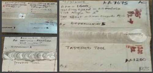
Aluminium alloys base materials: The aluminium alloy plates of AA 7075-T651 and AA 1200-H19 were used in this study. The welded samples are shown in These alloys were obtained from Bharat aerospace alloys, Gulalwadi, Mumbai, India.
Figure 1. Samples of welded materials with tapered tool
2.2. Chemical compositions analysis of the base metals
The chemical compositions of the procured parent materials AA7075-T651 and AA1200-H19 as shown in were determined using an optical emission spectrophotometer and found to conform to the supplier’s Material Safety Data Sheet (MSDS) and their mechanical properties are presented in
Table 1. Composition of base aluminium alloys (% wt)
Table 2. Mechanical properties of base metals
2.3. Compositions and the mechanical properties of AISI H13 steel tool
The welding tool was made up of AISI H13 chromium hot-worked steel tool with high strength. The choice of this material for the welding tool was based on its outstanding properties, such as a superior mixture of fatigue resistance and hot toughness, good thermal pressure resistance, easy to machine, high durability, and can be well endured under water cooling. The chemical composition of AISI H13 is summarized in . The following mechanical properties steered the choice of AISI H13 (see ) as a welding tool over the other materials: bulk module of 160 GPa, a shear module of 81 GPa, an ultimate tensile strength of 1990 MPa, break elongation of 9.0 percent, machinability of 50 percent, yield tensile strength of 1650 MPa, and the Poisson ratio of 0.30.
Table 3. The AISI H13 steel tool chemical composition
2.4. Process parameters
The rotational and welding speeds and tool tilt angles used are presented in . These variable parameters were chosen based on reported literature (Akinlabi et al., Citation2012; Dragatogiannis et al., Citation2019; Heena et al., Citation2016; Pankajneog & Pranav, Citation2014). The parameters were selected carefully from reported optimized values. A preliminary weld was performed and used as a basis for parameter selection.
Table 4. Rotational speed, welding speed and tilt angle
2.5. Methods
Aluminium alloys AA7075-T651 and AA1200-H19 both of thickness 6 mm were cut using a band saw to the required dimensions of 60 × 120 mm. The edges to be joined were milled to allow for proper lapping. The surface area of the proposed weld region was cleaned with emery paper to remove any oxide layer that may have been formed. The samples were washed using acetone to remove dirt or grease. The AA1200-H19 was placed on the advancing side while the AA7075-T651 Aluminium alloy was placed on the retreating side and properly clamped on the friction stir welding equipment (see ). HSS cylindrical tapered tool with shoulder diameter of 22 mm, probe length of 5.65 mm with mouth and root diameters of 5.5 and 7.3 mm respectively as shown in was used and the tool was offset at 2 mm towards the AA1200-H19 aluminium alloys (softer material). Friction stir welding was performed on the alloys along the rolling direction in a butt configuration arrangement using a two-tonne numerical stir welding equipment manufactured by ETA Technology Ltd Bangalore India with model N0 WS004. The final weldment was allowed to cool and unclamped from the machine. The chemical composition of the alloys is shown in obtained from the spectrometry analysis using the spectrometer (Model No 8113, serial No 45,767–545-TV5-5028). The mechanical properties of the base metals are presented in . The experiment was performed at the friction stir welding research laboratory, Indian Institute of Technology Kharagpur (IIT-KGP) India. The factor levels for the process factors are presented in in which rotational speed (RS), transverse speed (TS) and tool tilt angle (TTA) as process parameters and were used in analysing the mechanical properties of the weldment. Other parameters are plunge depth of 0.15 mm and axial load of 7kN. shows a schematic representation of friction stir butt welding between AA 1200-H19 and AA7075-T651 aluminium alloys. The ASTM-E8 (sub-size), ASTM E-23 (reduced specimen) standards were used respectively to prepare the tensile (Ikumapayi, Akinlabi, Majumdar et al., Citation2019) and impact test (Ikumapayi et al., Citation2018). Specimens such as Tensile, microhardness and Impact were taken from the final weldment across the weld as shown in .
Figure 2. (a) Friction stir welding equipment. (b) welding setup
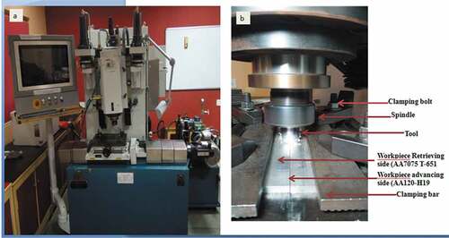
Figure 3. (a): AISI H13 steel tapered tool (b): Schematic representation of friction stir butt welding
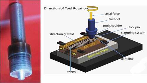
Figure 4. Tensile, microhardness and impact specimen
2.6. Mechanical testing of the weldment
Tensile testing was evaluated on the weldment by taking three tensile samples from each parameter by cutting across the weld region following ASTM-E8 standard methods (Bocchi et al., Citation2018; Ikumapayi & Akinlabi, Citation2019) for tensile strength evaluation of materials. The test was conducted using a 100 kN Instron 8862 testing machine. The specimen dimension is shown in . The UTS was obtained using the formula.
Figure 5. Tensile test specimen
2.7. Hardness evaluation
The hardness test was done in accordance with ASTM-E10 standard (Mulaba-Kapinga et al., Citation2020) using a 5 kg Vickers hardness tester (MHVD-10IS) and it was profiled across the weld direction measuring the resistance to indentation of each weldment. The load applied was at a dwell time of 15 seconds and 29 indentations were made at an interval of 1 mm on each sample. The values of the hardness measurements in the nugget zone were recorded as the average hardness of each sample. shows the dimensions of the hardness specimen.
Figure 6. Microhardness specimen
2.8. Impact testing
The Charpy impact test was assessed in accordance with ASTM-E23 standard (Ikumapayi et al., Citation2018) method (reduced specimen) which specified a notch angle of 45°, and a notch radius of 0.25 mm with 2 mm depth of notch at the base. The impact energy of each weldment was obtained using the Galdabani impact of 450 testing machines (Model: V92Q).
3. Results and discussion
3.1. Analysis of hardness
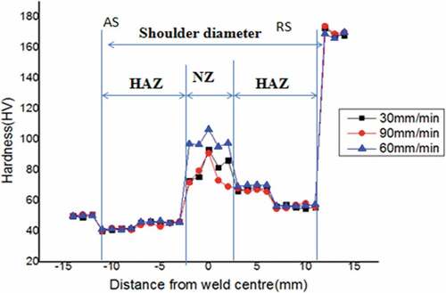
The hardness test performed on the two base metals gave hardness values of 50 HV and 175 HV as hardness values for AA1200-H19 and AA7075-T651 respectively. The profile of hardness is presented in . The mean values of hardness increase from 81.99 to 98.58 HV. This may be as a result of better grain refinement and mixing at 60 mm/min welding speed and this conforms to the result reported in Daniolos & Pantelis (Citation2017) Hariharan & Golden Renjith Nimal (Citation2014). Also, at the 60 mm/min welding speed precipitation of hardening precipitates was encouraged. At 30 mm/min welding speed, the average hardness of 81.99 HV obtained was higher than that of the AA 1200 H-19 aluminium alloy and below that of 7075-T651 indicating occurrence of mixing of both alloys at the nugget zone as perceived in the work of Dragatogiannis et al. (Dragatogiannis et al., Citation2016). At 90 mm/min welding speed (high speed) the average hardness decreases from 98.58 to 77 HV, this can be attributed to dissolution of strengthening precipitates (Bocchi et al., Citation2018). Also, at 90 mm/min welding speed, the tool traverses faster on the material (dwelling time was low) not giving sufficient time for material coalescence to occur. The obtained hardness mean values at the HAZ of the advancing side are lower than the hardness value of the base metal AA 1200 H-19 aluminium alloys, this may be attributed to the effect of heat generated during stirring and mixing stage resulting in the dissolution of the alloy’s precipitates and leading to reduction in hardness (Cavaliere et al., Citation2009). On the retreating side, the hardness values were lower than that of the base metal AA7075-T651 and this is in line with the work of Guo, et al. (Guo et al., Citation2014). The average hardness value obtained at the NZ was higher than that of the base metal AA1200-H19 but lower than the base metal AA7075-T651. This is due to the mixing of both allows at this region. Also, the average hardness at the NZ is higher than those of the HAZ of both the advancing and retreating sides. This can be attributed to the presence of intermetallic compounds formed during the welding (Abolusoro et al., Citation2020).
Figure 7. Hardness profile showing various zones at varying welding speed for TT
3.2. Impact energy at different weld speed
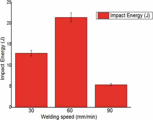
From , the impact energy increased from 12.9 to 21.4 J when the welding speed was increased from 30 mm/min to 60 mm/min. This can be attributed to proper bonding at medium speed of 60 mm/min welding speed as compared to low welding speed of 30 mm/min, an indication that welding speed of 60 mm/min encourages proper mixing and bonding as also reported in the work of Ikumapayi et al. (Ikumapayi et al., Citation2018). Also, at 90 mm/min welding speed, the impact energy decreased from 21.4 to 5.4 J, this may be because at 90 mm/min (higher welding speed) the tool traverses faster and not giving sufficient room for material coalescence to occur.
Figure 8. Effect of welding speed on impact energy
3.3. Tensile strength evaluation
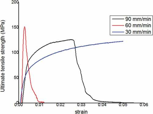
shows the plot for stress-strain relationship obtained for the combination of parameters in dissimilar welded joints at 30 mm/min, 60 mm/min and 90 mm/min travel speed. Each segment addresses a thorough examination of the findings. The percentage elongations for the weldment were also induced by microstructural evolution in the welded joint due to a rise in heat flux (Daniolos & Pantelis, Citation2017). The bonding precipitates are coarsened, owing to weaker grain bonding, thereby reducing the welds’ tensile strength as reported in (Abolusoro et al., Citation2020; Mulaba-Kapinga et al., Citation2020).
Figure 9. Tensile strength showing the effect of various welding speed
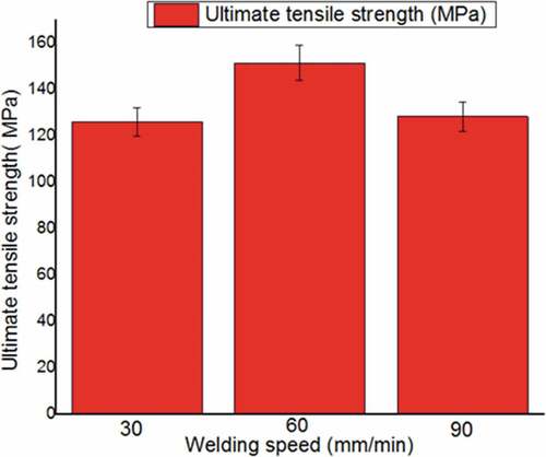
3.3.1. Effect of welding speed on Ultimate Tensile Strength (UTS)
examines the result of welding speed on ultimate tensile strength at 30 mm/min, 60 mm/min and 90 mm/min travel speed. It was noted that the UTS increased from 126.04 to 151.54 MPa with an increase in welding speed from 30 mm/min to 60 mm/min and this may be as a result of the increase in grain refinement that encouraged material bonding between the two alloys and this is in consonant with the study in (Akinlabi et al., Citation2012; Abolusoro et al., Citation2020). The UTS obtained was below that of the parent alloys, although the UTS obtained at the three parameters as expected are lower than those of the base metals as also indicated in the work reported by Daniolos et al. (Daniolos & Pantelis, Citation2017) and Akinlabi et al. (Akinlabi et al., Citation2012), however, their joint efficiencies which are significant enough is an indication of good bonding between the two alloys. Also, it can be added that the welding speed of 60 mm/min promotes better material mixing and bonding for the tapered tool weldment (Elangovan et al., Citation2008). At 90 mm/min welding speed, the speed was high not giving enough time for material mixing and coalescence to occur as compared to the UTS value obtained at 60 mm/min welding speed.
Figure 10. UTS at varying welding speed
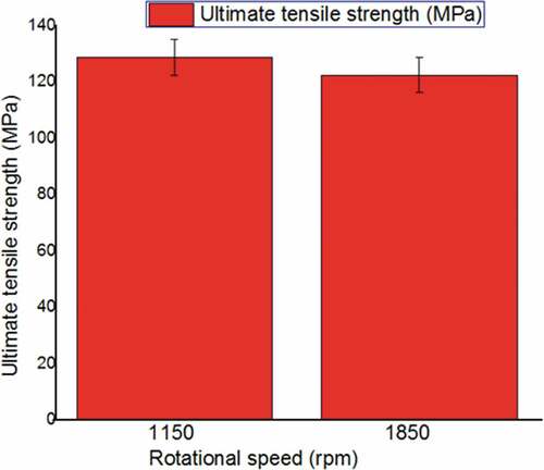
3.3.2. Effect of rotational speed on Ultimate Tensile Strength
At machine rotational speed of 1150 rpm, the total tensile strength of the welds is significantly higher than those of 1850 rpm. This may be due to the increase in thermal energy produced by the tool at higher temperature (Elangovan et al., Citation2008) suggesting that lower rotational velocity of 1150 rpm favours higher UTS value and these trends were also noticed in the work reported by Abolusoro et al. (Abolusoro et al., Citation2020). displays the UTS plot at two different tool rotational speeds.
Figure 11. UTS at varying rotational speed
3.4. Tilt angle
3.4.1. Effect of tilt angle on the hardness
The average hardness value at constant tool rotational and transverse speeds correspond to 1500 rpm and 60 mm/min respectively. It was observed that hardness values increase from 70.22 HV to 98.58 HV with an increase in tool tilt angle from 1° to 2° due to the formation of intermetallic resulting from temperature rise in the stir zone. Also, this is because the tilt angle prevents the spreading of material on the surface of the weldment which may result in flash defects (Lombard et al., Citation2008). The tilt angle encourages material flow which results in good metallurgical bonding between the two alloys (Dragatogiannis et al., Citation2016). A further increase in tilt angle from 2° to 3° resulted in a reduction in hardness from 98.58 HV to 66 HV. depicts hardness values at varying tilt angles.
Figure 12. Hardness values at varying tilt angle
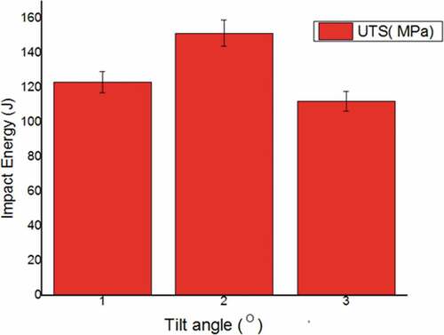
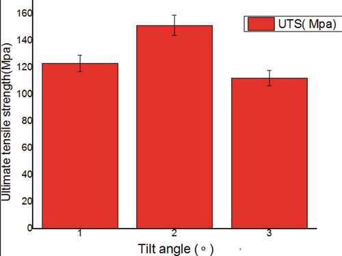
3.4.2. Influence of varying tilt angles on UTS
The UTS has presented in was noticed to have increased from 123.32 MPa to 151.54 MPa and this is attributed to the increase in tilt angle from 1° to 2° and the UTS was also noticed to have declined to 122.2 MPa when the tilt angle is raised from 2° to 3°. An indication that tool tilt angle of 2° favours better material transport leading to better mixing of the alloys and proper metallurgical bonding as well as the formation of defect-free and smooth joints which are products of the increased tensile strength of the weldment (Cavaliere et al., Citation2009; Prabha et al., Citation2018; Vinayak & Bhatwadekar, Citation2015).
Figure 13. UTS values at varying tilt angle
3.4.3. Effect of tilt angle on impact energy
At steady rotational and welding speeds corresponding to 1500 rpm and 60 mm/min respectively, and changing the tilt angle of the tool, the impact energy increases as the tilt angle rises to a certain point and then starts to decrease as illustrated in . The tilt angle of 2° gave the highest average impact energy value of 21.4 J. This is because, at this angle, better tool shoulder and workpiece surface interaction are resulting in better plastic deformation and mixing of the alloys.
Figure 14. A plot of tilt angles on impact energy
4. Conclusions
The effect of input parameters on the material characteristics of dissimilar friction stir welded AA7075-T651 and AA1200-H19 using the tapered tool was analyzed and the accompanying evidences have been found:
Dissimilar friction stir welding between AA 7075-T6 and AA 1200-H19 was successful
The overall tensile strength of the friction stir welded joints increased with rotational speed from 128.79 MPa at 1150 rpm to 151.54 MPa at 1500 rpm and decreased to 122.47 MPa at 1850 rpm.
The average hardness of the two alloys is higher than that of the softer 1200-H19 but lower than that of the harder AA 7075-T651 aluminium alloys
From the analysis of results, medium welding speed (60 mm/min) encourages material coalescence better than higher welding speed of 90 mm/min.
There was a decrease in hardness from 98.58 to 77 HV when the welding speed was decreased from 90 mm/min to 60 mm/min which is also an indication that higher welding speed does to encourage material coalescence and consequently does not favour hardness.
Proper bonding of alloys can be achieved at 60 mm/min hence higher impact energy of 21.4 J as against impact energy of 5.4 J obtained at 90 mm/min and 12.9 J obtained at 30 mm/min.
Acknowledgements
The authors gratefully acknowledge the support given by the Chair of the Friction stir welding Laboratory (Prof. Surjya K. Pal) in the department of Mechanical Engineering, Indian Institute of Technology, Kharagpur, India and the support received from Prof. Esther T. Akinlabi – The Director of Pan African University for Life and Earth Sciences Institute (PAULESI), Ibadan, Nigeria for the research trip to India.
Additional information
Funding
Notes on contributors

Benjamin I. Attah
Benjamin Ileh Attah is an engineer at the Federal Radio Corporation of Nigeria and is currently a PhD research scholar at the Department of Mechanical Engineering, Federal University of Technology Minna Nigeria. He was an intern doctoral scholar at the Indian Institute of Technology, Kharagpur, India. His research interests include metal casting, surface modifications, friction stir and electron beam welding.
Sunday Albert Lawal is an Associate Professor of Mechanical Engineering at the Federal University of Technology Minna. He is the current Head of Department of Mechanical Engineering at the Federal University of Technology Minna.
Esther Titilayo Akinlabi is a Professor of Mechanical Engineering. She is currently serving as the Director of the Pan African University for Life and Earth Sciences Institute (PAULESI), Ibadan, Nigeria.
Katsina Christopher Bala is an Associate Professor of Mechanical Engineering with specialization in Industrial and Production Engineering, Federal University of Technology, Minna.
References
- Abolusoro, O. P., Akinlabi, E. T., & Kailas, S. V. (2020). Tool rotational speed impact on temperature variations, mechanical properties and microstructure of friction stir welding of dissimilar high-strength aluminium alloys. Journal of the Brazilian Society of Mechanical Sciences and Engineering, 42(4), 176. https://doi.org/10.1007/s40430-020-2259-9
- Abolusoro, P. O., & Akinlabi, E. T. (2020). in-process cooling in friction stir welding of aluminium alloys-an overview. In M. A. Al. et (Ed.), Advances in material sciences and engineering, lecture notes in mechanical engineering (pp. 435–14). Springer Nature Singapore Pvt. Ltd.
- Akinlabi, E. T., Annelize, E., & Patrick, J. M. (2012). Effect of travel speed on joint properties of dissimilar metal friction stir welds. Second International Conference on Advances in Engineering and Technology, Noida, India.
- Bocchi, S., Cabrini, M., D’Urso, G., Giardini, C., Lorenzi, S., & Pastore, T. (2018). The influence of process parameters on mechanical properties and corrosion behaviour of friction stir welded aluminium joints. Journal of Manufacturing Processes, 35, 1–15. https://doi.org/10.1016/j.jmapro.2018.07.012
- Cavaliere, P., De Santis, A., Panella, F., & Squillace, A. (2009). Effect of welding parameters on mechanical and microstructural properties of dissimilar AA6082-AA2024 joints produced by friction stir welding. Materials & Design, 30(3), 609–616. https://doi.org/10.1016/j.matdes.2008.05.044
- Cole, E. G., Fehrenbacher, A., Duffie, N. A., Zinn, M. R., Pfefferkorn, F. E., & Ferrier, N. J. (2014). Weld temperature effects during friction stir welding of dissimilar aluminium alloys 6061-t6 and 7075-t6. The International Journal of Advanced Manufacturing Technology, 71(1), 643–652. https://doi.org/10.1007/s00170-013-5485-9
- Daniolos, N. M., & Pantelis, D. I. (2017). Microstructural and mechanical properties of dissimilar friction stir welds between AA6082-T6 and AA7075-T651. The International Journal of Advanced Manufacturing Technology, 88(1), 2497–2505. https://doi.org/10.1007/s00170-016-8965-x
- Dragatogiannis, D. A., Kollaros, D., Karakizis, P., Pantelis, D., Lin, J., & Charitidis, C. (2019). Friction stir welding between 6082 and 7075 aluminum alloys thermal treated for automotive applications. Materials Performance and Characterization, 8(4) ,571-589. https://doi.org/10.1520/MPC20180179
- Dragatogiannis, D. A., Koumoulos, E. P., Kartsonakis, I. A., Pantelis, D. I., Karakizis, P. N., & Charitidis, C. A. (2016). Dissimilar friction stir welding between 5083 and 6082 Al alloys reinforced with TiC nanoparticles. Materials and Manufacturing Processes, 31(1), 2101–2114. https://doi.org/10.1080/10426914.2015.1103856
- Elangovan, K., Balasubramanian, V., & Valliappan, M. (2008). Influences of tool pin profile and Axial force on the formation of friction stir processing zone in AA6061 aluminium alloy. The International Journal of Advanced Manufacturing Technology, 38(1), 285–295. https://doi.org/10.1007/s00170-007-1100-2
- Ghosh, M., Kumar, K., Kailas, S. V., & Ray, A. K. (2010). Optimization of friction stir welding parameters for dissimilar aluminium alloys. Materials & Design, 31(1), 3033–3037. https://doi.org/10.1016/j.matdes.2010.01.028
- Guo, J. F., Chen, H. C., Sun, C. N., Bi, G., Sun, Z., & Wei, J. (2014). Friction stir welding of dissimilar materials between AA6061 and AA7075 Al alloys effects of process parameters. Materials & Design (1980–2015), 56(1), 185–192. https://doi.org/10.1016/j.matdes.2013.10.082
- Han, M. S., Lee, S. J., Park, J. C., K.o, S. C., Woo, Y. B., & Kim, S. J. (2009). Optimum conditions by mechanical characteristic evaluation in friction stir welding for 5083-O Al alloy. Transactions of Nonferrous Metals Society of China, 19(1), 17–22. https://doi.org/10.1016/S1003-6326(10)60238-5
- Hariharan, R., & Golden Renjith Nimal, R. J. (2014). Friction stir welding of dissimilar aluminium alloys (6061&7075) by using computerized numerical control machine. Middle East Journal of Scientific Research, 20(1), 601–605. DOI:10.5829/idosi.mejsr.2014.20.05.201
- Heena, K. S., Kamlesh, B., Krunal, S., & Unnati, J. (2016). Experimental analysis of friction stir welding of dissimilar alloys AA6061 and Mg AZ31 using circular butt joint geometry, 3rd International Conference on Innovations in Automation and Mechatronics Engineering ICIAME 2016 Procedia TechnologyVallah Vidhyanagar India, 23( 1), 566–572.
- Ikumapayi, O. M., & Akinlabi, E. T. (2019). Comparative assessment of tensile strength and corrosion protection in friction stir processed AA7075-T651 matrix composites using Fly Ashes nanoparticle as reinforcement inhibitors in 3.5 % NaCl. International Journal of Mechanical and Production Engineering Research and Development, 9(3), 839–854. DOI:10.24247/ijmperdjun201992
- Ikumapayi, O. M., Akinlabi, E. T., & Majumdar, J. D. (2019). Influence of carbonaceous agrowastes nanoparticles on physical and mechanical properties of friction stir processed AA7075-T651 metal matrix composites. Surface Topography: Metrology and Properties, 7(3), 1–17. DOI:10.1088/2051-672X/ab3aae
- Ikumapayi, O. M., Akinlabi, E. T., Majumdar, J. D., & Akinlabi, S. A. (2019). Influence of 17–4PH stainless steel and α+ꞵ titanium alloy powders for corrosion susceptibility on friction stir processed AA7075-T651 aluminium matrix composites. Journal of Bio Tribo Corrosion, 5(4), 1–11. https://doi.org/10.1007/s40735-019-0294-9
- Ikumapayi, O. M., Okokpujie, I. P., Afolalu, S. A., Ajayi, O. O., Akilabi, E. T., & Bodunde, O. P. (2018). Effects of quenchants on impact strength of Single-Vee Butt welded joint of mild steel. IOP Conference Series: Materials Science and Engineering 391, 012007, Kaula Lumpur, Malaysia. https://doi.org/10.1088/1757-899X/391/1/012007
- Kum., L., Jarrar, F., Sheikh- Ahmed, J., & Ozturk, F. (2017). Using coupled Eulerian-Lagrangian Formulations for accurate modelling of the friction stir welding process. Procedia Engineering, 207, 574–579. https://doi.org/10.1016/j.proeng.2017.10.1023
- Lombard, H., Hattingh, D. G., Steuwer, A., & James, M. N. (2008). Optimising FSW process parameters to minimise defects and maximise fatigue life in 5083-H321 aluminium alloy. Engineering Fracture Mechanics, 75(1), 341–354. https://doi.org/10.1016/j.engfracmech.2007.01.026
- Mulaba-Kapinga, D., Nyembwe, K. D., Ikumapayi, O. M., & Akinlabi, E. T. (2020). Mechanical, electrochemical and structural characteristics of friction stir spot welds of Aluminium Alloy 6063. Manufacturing Review, 7(25), 1–15. https://doi.org/10.1051/mfreview/2020022
- Pankajneog, D. T., & Pranav, K. P. (2014). Optimizations of Friction stir welding parameters in joining dissimilar aluminium alloys using SPSS and Taguchi. Journal of Basic and Applied Engineering Research, 1(1), 25–27. https://www.khrishsankriti.org/jbear.html
- Prabha, K. A., Putha, P. K., & Prasad, B. S. (2018). Effect of tool rotational speed on mechanical properties of aluminium alloy 5083 weldments in friction stir welding. Materials Today: Proceedings, 5(1), 18535–18543. https://doi.org/10.1016/j.matpr.2018.06.196
- Shaikh, M. S., & Yagnesh, B. C. (2015). Optimization of friction stir welding process parameters for welding aluminium alloys. International Journal of Science Technology & Engineering, 2(2), 69–75. https://ijste.org/articles/IJSTEV212015.pdf
- Vinayak, D. Y., & Bhatwadekar, S. G. (2015). Friction stir welding of dissimilar aluminium alloys AA1100 to AA6101-T6. International Journal of Research in Aeronautical and Mechanical Engineering, 3(1), 2321–3051. https://www.researchgate.net/publication/272483306-friction-stir-welding-of-dissimilar-Aluminium-alloys-AA1100-to-AA6101-T6