?Mathematical formulae have been encoded as MathML and are displayed in this HTML version using MathJax in order to improve their display. Uncheck the box to turn MathJax off. This feature requires Javascript. Click on a formula to zoom.
Abstract
There have been reported cases of wellbore instability near-wellbore area due to failures associated with drilling operations, the magnitude and extension of the failure area is imprecisely evaluated by copious researchers due to some of the limitations posed by the numerical simulations used. Therefore, this paper estimates a failure zone area near-wellbore based on the conducted coupled Thermal-Hydro Mechanical (THM) analysis integrated into UDEC, wellbore enlargement, and Failure area analysis. A two-dimensional horizontal plane stress model of 2 × 2 m is created using rock properties from a vertical well, and a wellbore radius of 0.11 m is drilled under confined stress using the in-situ stresses. The Voronoi tessellation joint system was used to create randomly polygon fractures referred to as Discrete Fracture Size (DFS). The coding of various parameters was performed to study the near-wellbore stability for both underbalanced and overbalanced drilling conditions, the four cases of DFS were used against seven wellbore pressures. After comparing with other DFS, The parametric analysis at DFS of 0.1 and 0.12 m offers low shear and block displacements that led to an induced shear and tensile failures, respectively. However, to evaluate the optimal DFS, a comparison is done using Failure area and Borehole enlargement analysis, and the results show that DFS of 0.12 m yields significantly low wellbore enlargement rate and failure area zone for all stress ratios and drilling cases. The proposed simple model for wellbore failure area estimations is verified against a well vertical section located in Northern China.
Public Interest Statement
Drilling is a complex process where a hole is made by penetrating the subsurface rock formation. To have an optimal and cost effective drilling operations, the research was done focusing on the various techniques to reduce the cost associated with the drilling operations. It has been reported in several articles that problems related to drilling fluid losses into the fractured formation account for between 20-30% of the total drilling cost. Also, it has to be understood that drilling fluid costs as much as $300 per barrel, which is about 25% of the total drilling cost. It is obvious that no one is ready to produce oil and/or gas at a higher production cost. Consequently, competitions in today’s dynamic market conditions have triggered engineers and researchers to devote their time and energy to ways of minimizing the cost associated with the said losses. Therefore, our research underwrites to the world the techniques which reduce wellbore failures which are the main conduits of drilling fluids leakages.
1. Introduction
The stability of the wellbore is affected by the in-situ stress system of the hydrocarbon formations. Once a well is drilled, the rock mass near the wellbore experiences a stress concentration previously taken by the removed rock (Yousefian et al., Citation2020). The removed rocks destabilize the wellbore, thereby maintaining the stable well is one of the difficult challenges facing drilling operation, this challenge may still prevail even though the well is drilled underbalanced or overbalanced. If the stress concentration exceeds the strength of the surrounded rock, a failure zone will be formed around the borehole wall, leading to instability problems for a drilling operation (Khatibi et al., Citation2018; Ma & Yu, Citation2019; Zoback, Citation2010). To evaluate whether a failure will occur at the borehole wall under the given in situ stresses, pore pressure, and borehole pressure, some failure criteria can be invoked to check whether the shear stresses in the borehole wall exceed the shear strength of the rock (Lavrov, Citation2016). Analyses of borehole enlargement/collapse for hundreds of field cases suggest that the Mohr-Coulomb failure criterion is most suitable to be applied in sandstone formations (Li & Bai, Citation2011). Generally, there are two types of mechanical wellbore failures associated with drilling operation near the wellbore, tensile failure which represents formation fracturing which may, in turn, lead to lost circulation, and shear failure which can cause borehole problems such as stuck pipe and differential sticking (Al-Khayari et al., Citation2016). Yousefian, Fatehi Marji (Yousefian et al., Citation2020) proposed an analytical model using a linear elastoplastic theory to optimize well trajectory based on mud pressure and failure zone, in their study, it was concluded that optimizing well trajectory based on the failure area is more reasonable and logical. Thus, the most stable drilling paths were suggested for vertical and deviated (<45°) borehole.
Numerous scholars (Karatela et al., Citation2016) have investigated on borehole stability of heavily fractured rock by considering underbalanced drilling conditions using DEM, however, their study did not investigate on overbalanced drilling conditions. On the other hand, the study conducted using finite methods has found that both overbalanced and underbalanced drilling conditions can affect the stress state near-wellbore due to pore pressure change (Jia et al., Citation2019). Unlike the finite element method, UDEC is more capable to perform an analysis of fluid flow through the fractures. A fully coupled mechanical-hydraulic analysis is performed in which fracture conductivity is dependent on mechanical deformation and, conversely, fluid pressure affects the mechanical behavior of the fractures (Zhang & Sanderson, Citation2002). Fluid losses to the formation are due to drilling-induced fracture (Alberty & McLean, Citation2004). Therefore, this study explores the effects of underbalanced and overbalanced drilling conditions on various parameters of considerations.
This work proposes a model to estimate the failure zone area for DFS of 0.12 m, based on coupled Thermal-Hydro Mechanical (THM) analysis integrated into UDEC followed by failure area and wellbore enlargement analysis.
1.1. Elastic-plastic yield model
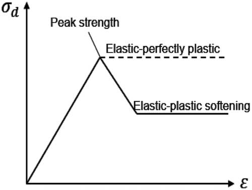
Most of the studies conducted assume the rock fails in a brittle mode based on a linear elasticity assumption. Nevertheless, real rocks do not always undergo brittle failure, but rather often behave in an elastic-plastic manner (Chuanliang et al., Citation2015; Li et al., Citation2018). Unlike elastic deformation, plastic deformation is not recovered when the load causing the deformation is released (Fjar et al., Citation2008; Li et al., Citation2018). The Mohr-Coulomb failure criterion is one of the earliest and most trusted failure criteria for rocks. This criterion assumes that failure happens when the shear stress on a specific plane reaches the shear strength (Li & Bai, Citation2011; Mehranpour & Kulatilake, Citation2016). The Mohr-Coulomb (MC) model is an elastic-perfectly plastic yield model. The yield point in a typical plastic stress-strain curve defines the onset of plastic deformation (see ). The yield criterion, similar to the failure criterion, defines the surface in the stress space where plasticity is initiated (Fjar et al., Citation2008). If a tensile failure occurs in a zone, the tensile strength is set to zero for that zone (Itasca, Citation2011). Analyses of borehole enlargement/collapse for hundreds of field cases suggest that the Mohr-Coulomb failure criterion is most suitable to be applied in sandstone formations (Li & Bai, Citation2011). Therefore, this study used the MC criterion to estimate the failure zone area near the wellbore for fractured sandstone rock in vertical wells.
Figure 1. Elastic-plastic rock behavior
1.2. Coulomb slip model
The numerical modeling shown in this paper was performed with the numerical code UDEC. The joints are represented numerically as a contact surface formed between two block edges. The constitutive laws applied to the contacts as shown in EquationEq. 1(Eq. 1)
(Eq. 1) (Itasca, Citation2011; Zhang & Sanderson, Citation2002):
Where the effective normal stress increment, is the normal displacement increment,
the elastic component of the incremental is shear displacement, and
is the total incremental shear displacement.
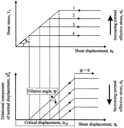
shows that joint dilation can happen at the onset of nonelastic sliding, and normally is governed in the Coulomb slip model by a specified dilation angle, ψ. The accrued dilation is usually controlled by either a high normal stress level or a maximum shear displacement that exceeds a critical value, .This limitation on dilation corresponds to the observation that crushing of asperities at high normal stress or large shearing would ultimately stop the joint from dilating (Itasca, Citation2011). This behavior of joint dilation is described as the Coulomb slip model.
Figure 2. Basic fracture behavior model used in UDEC (modified from Itasca, 1996)
If
then
. This model is described as the Coulomb slip model and is illustrated in
Tensile failure occurs when the effective tensile stress acting on some plane exceeds the tensile strength (). Many scholars (Lavrov, Citation2016; Yongfeng et al., Citation2009) proposed and used the tensile failure criterion as given in EquationEq. (4)
(Eq. 4)
(Eq. 4) to predict the tensile failure in the direction of the most tensile principal stress
.
2. Methodology
2.1. Modelling approach
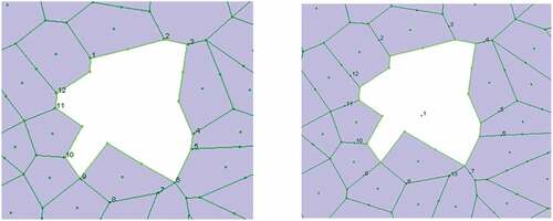
The horizontal plane stress model of 2 × 2 m was considered, the block model is deformed by creating discontinuities using the properties listed in , and . The discontinuities were created by using the Voronoi joint set due to its advantage in interaction with large deformation, stress, and fluid flow through contact elements (Itasca, Citation2011; Jing & Stephansson, Citation2007; Nicolson & Hunt, Citation2004; Yetisir et al., Citation2016). A typical example of the Voronoi tessellation model is shown in , for easiness of simulating a possible fluid pathways network through rock mass, the region around the wellbore is zoned into randomly shaped fractures called DFS, Accordingly, this paper analyzes different values of DFS such as 0.07, 0.1, 0.12, 0.14, and 0.15 m.
Figure 3. Deformable model shape: (a) before in situ stress applied and (b) after stress equilibrium
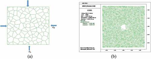
Table 1. Model parameters for UDEC simulation
Table 2. Rock and thermal properties
Table 3. Rock joint properties
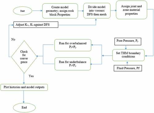
demonstrates the model geometry and boundary stress conditions of an example vertical well whose radius is 0.11 m, the minimum, and maximum horizontal stresses are 48 and 68 MPa, respectively, while the vertical stress of 62 MPa is applied at 2567 m. The pore pressure was 28MPa and the drilling fluid pressures used for underbalanced and overbalanced drilling are 27.2 MPa and 28.8 MPa, respectively. shows the distribution of stresses around the wellbore of the drilled deformable block model after the in-situ stresses and boundary conditions for velocity, stress, thermal, and fluid property values were executed. demonstrates the wellbore response to induced stresses due to disturbances caused by removed rock as a result of drilling. The summarized flow diagram is indicated in
Figure 4. Flow diagram for modelling process
2.2. Parametric analysis approach
The comprehensive parametric analysis was carried out using the coupled THM into UDEC to study the most influential parameters to the wellbore instability. By considering the relative distance from the wellbore axis, the point locations were selected at the contact points intersecting the wellbore. Based on this study the twelve near-wellbore locations were found to intersect the wellbore. Therefore, these points were examined to establish their possible failure response due to the variability of parameters. The analysis involved keeping some of the parameters constant to study the effect of others. The parameters analyzed are DFS, flow rate, pore pressure, temperature, and stresses. Notably, the effect of pore pressure and temperature parameters were analyzed at domain/grid locations shown in , whereby displacement, flow rate, and stresses were checked at contacts location in .
Figure 5. Near wellbore showing history locations: (a) left contacts and (b) right domain
2.3. Estimating failure area zone near-wellbore
The results from simulations provided the extension of the failure zone near the wellbore. To quantitatively determine the failure area, the radius of the failure zone is a paramount factor of consideration. A different approach was employed to estimate this radius of failure using plastic analysis (Yousefian et al., Citation2020) proposed an equation to estimate the radius of the failure zone by substituting borehole stresses in the failure criterion to obtain an equation in terms of r. The shapes of wellbore after deformation depends significantly on the magnitude of stresses applied to it, therefore different stress ratio would provide either a circle or an eclipse shape. Therefore, during modeling, it is irrational to assume the geometrical symmetry in rock behavior when estimating the radius of the failure zone because of the unfathomable nature of deformations. Thus, this study applied the coordinates of the extended failure zone and substitute them into EquationEq. (5)Eq. (5)
Eq. (5) to determine the radius of the failure zone and in turn compute the relative failure zone. The study opted to use the terms damage zone/failure zone near-wellbore interchangeably as illustrated in , therefore the failure zone area (FA) can be determined as the area difference between the ellipse and borehole, and the extension rate is as shown in EquationEq.5
Eq. (5)
Eq. (5) .
Figure 6. Failure/damage zone near the wellbore wall (Jia et al., Citation2019; Yousefian et al., Citation2020)
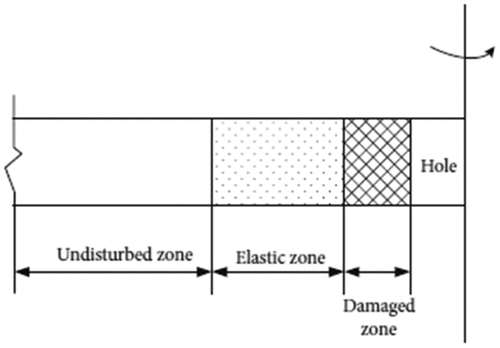
Where; a and b are the minor axis of an ellipse and major axis of the ellipse, respectively.
2.4. Wellbore enlargement analysis
As already explained, once the well is drilled the stress distribution may cause some of the rock grains surrounding the wellbore to detach and/or fall as chippings into the wellbore, this process is causing the borehole to enlarge. If the casing operation delays the wellbore can lead to breakout formation and/or washout. In this study, we have assessed the degree of enlargement using EquationEq.6(Eq.6)
(Eq.6) . The rate at which the borehole enlarge was determined by the following equation:
For the selected depth of study a WER below 15% is considered as a stable condition to prevent rock spalling, washouts, breakouts, and maintain wellbore integrity for tripping time of 2.8 h before casing.
3. Results and Discussions
3.1. Effect of fluid pressure on wellbore failure
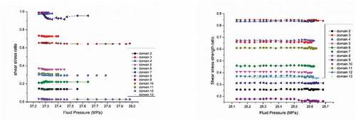
The wellbore failure takes place when the rock stress exceeds the rock strength, and the fluid pressure tends to change the stress state near the wellbore. Accordingly, in this section, the effect of fluid pressure on the shear stress-strength ratio (SSR) at different near-wellbore locations were analyzed. compares the stability of joints for two drilling cases using different values of pressure on every joint. For both drilling cases, wellbore stability is assessed using SSR, the higher the SSR, the more improved stability, for underbalanced drilling, the fluid flows inwards triggered unstable joints at domains 2, 5, 6, 8, 11, 12, and 13 with SSR below 0.5 with joint 8 became the most unstable with the maximum shear displacement of 67.7 , while overbalanced drilling reversed the fluid flow direction causing the unstable joints at domains 2, 5, 6, 7, 9, 12, and 13. Although point 9 became the most unstable with the maximum shear displacement decreased to 62.3
. Therefore, most of the domains in overbalanced drilling are somewhat more stable than that of underbalanced drilling.
Figure 7. Shear stress-strength ratio for underbalanced drilling (left) and overbalanced drilling (right)
3.2. Effect of discrete fracture size on wellbore failure
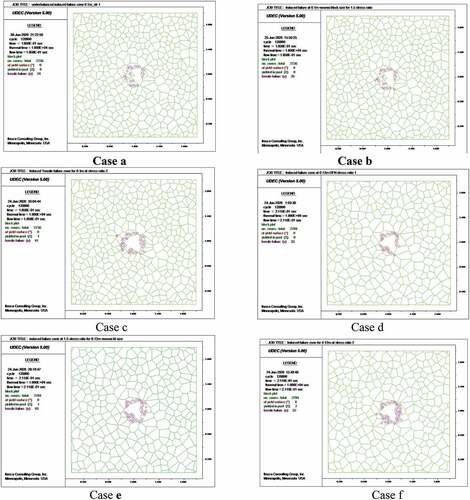
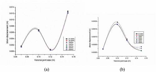
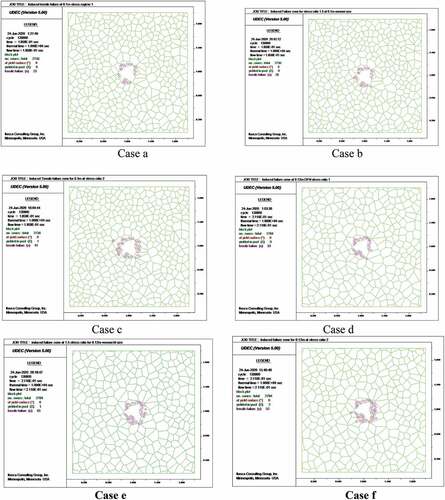
In this section, the four DFS were studied, the maximum block and shear displacements were recorded for every overbalanced and underbalanced drilling conditions. revealed that DFS of 0.12 m gives low block and shear displacement values. Also, Appendices 1 and 2 demonstrate that the number of induced tensile failure increases with the increase of DFS at constant pressure for all drilling cases. On the contrary, the increase of pressure at the same DFS did not change the magnitude of the induced failures. The critical case occurred at underbalanced pressure of 27.2 MPa where the number of tensile failures at zones reached 52 zones with 2 zones yielding (see Case f appendix 2).
Figure 8. Effect of DFS to wellbore failure: (a) block and (b) shear displacements at different underbalanced and overbalanced drilling pressures
3.3. Effect of in-situ stress ratio
3.3.1. Failure Area (FA) analysis
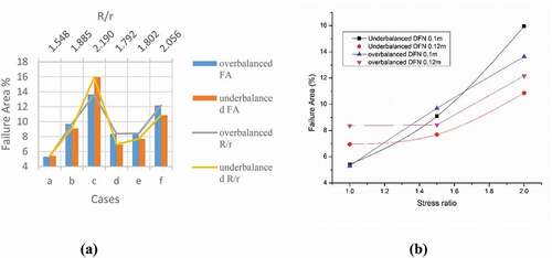
demonstrates that, for all drilling cases at DFS of 0.1 m, low values of failure area are obtained at a stress ratio of 1 which indicates stability around the wellbore, however, as this ratio increases the failure area extended toward the unstable zone. On the other hand, for DFS of 0.12 m, all drilling cases show that the failure area is higher than that of 0.1 m for the same stress ratio and gradually increases as the ratio increase (see ). Besides, also reveals that as the radial distance increases the FA value rises sharply to Case c and drops rapidly to Case d and e then rises again to Case f. The high peaks of FA values are due to the high-stress ratio.
Figure 9. Effects of failure area and radial distance for different drilling cases (a); Effect of stress ratio to failure area for different DFS (b)
EquationEq.7(Eq.7)
(Eq.7) and Equation8
(Eq. 8)
(Eq. 8) show the simple models for overbalanced drilling conditions extracted from the curves in for DFS values of 0.1 m and 0.12 m, respectively.
Eq. 8 can be used to predict the failure area extension given the horizontal in-situ stresses. The first derivative of EquationEq.8(Eq. 8)
(Eq. 8) is taken with respect to
and equated to zero to find the optimal value of the horizontal stress ratio that would provide the least failure zone area near the wellbore. Thus, EquationEq.10
(Eq.10)
(Eq.10) gives
, when substituted to EquationEq. 7
(Eq.7)
(Eq.7) and Equation8
(Eq. 8)
(Eq. 8) correspond to
of 7.46 and 7.94%, respectively
The values enlisted in , were used to verify the model the in-situ stress ratio of 1.42 is substituted in EquationEq.8(Eq. 8)
(Eq. 8) to provide the failure area of 8.17%.
3.4. Wellbore enlargement (WE) analysis
The WE analysis was conducted using EquationEq. (7(Eq.7)
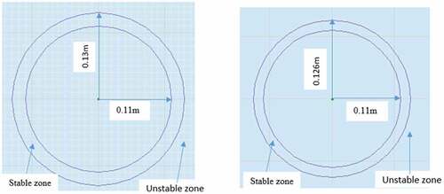
(Eq.7) ), the simulation results for both overbalanced and underbalanced drilling conditions were analyzed. It was found that near-wellbore enlargement is significantly affected by the degree of fracturing caused by DFS for overbalanced condition, nonetheless, in-situ stress ratio and wellbore pressure have been found not to affect the near-wellbore enlargement. The underbalanced drilling cases are seen in Appendix 2 (cases a and b) show that wellbore collapse due to pressure decline causing spalling of rock debris. Therefore, based on the radius of enlargement due to induced stress, the minimum WER value of 15% is obtained at DFS of 0.12 m and radius of 0.126 m as shown in (right). The annulus between two radii is considered to be a stable zone.
Figure 10. Radius of damage due to enlarged borehole showing stable and unstable zones for DFS 0.1 m (left) and 0.12 m (right)
4. Conclusion
Given the main objective of this paper is to establish the failure zone near the wellbore using UDEC codes to perform THM, borehole enlargement, and failure area analysis. The simulation results for both drilling conditions provide the following conclusions.
•The parametric analysis found that SSR is one of the most vital parameters to predict the wellbore failure around the wellbore. Different joints were studied near the wellbore under two drilling cases. An overbalanced drilling condition provides a lesser amount of shear failure as compared to underbalanced drilling conditions. However, both cases reveal that 71% of the joints were unstable, therefore for this case study precautions need to be taken to strengthen the wellbore.
•The coupled THM study reveals that drilling slightly underbalanced results in a 10 times increase of shear failure due to displaced blocks near the wellbore as compared to an overbalanced case. Hence, the magnitude of tensile failure raises from 40 to 45.
•The fractured formation accelerates the seepage of drilling fluid; therefore, it was suggested to study its degree of fracturing on the wellbore failure. Randomly DFS’s simulated show that optimal values of DFS were 0.1 m and 0.12 m due to low displacement. However, DFS of 0.1 m has been proven in this study to provide a lower number of tensile failure of 23 under the same horizontal stress ratio (1) than that 0.12 m which gives 33 making a 43% increase. On the other hand, an increase in horizontal stress ratios from 1 to1.5 and 1.5 to 2 increased the number of tensile failures generated by 13% and 58%, respectively. Therefore, operating under zones of higher values of DFS and horizontal stress ratios places the wellbore under severe wellbore failure problems, and should be avoided during planning.
•Moreover, the proposed model found that operating in a high in-situ stress ratio above 1.24 intensifies the risk of wellbore failure due to prolonged failure area extension. The simple model developed can be used to predict the failure area when the in-situ stress ratio is known for a given set of DFS in a fractured rock formation, however, more validation needs to perform when used in different formations such as shale.
•The conducted WEA provides a better understanding of how a slight increase in DFS can decrease the stability zone. Therefore, this study confirms that an integrated approach of parametric analysis, borehole enlargement, and Failure Area analysis has provided the best insight to estimate the damage zone as a result of shear and tensile failures using randomized Voronoi tessellation polygons herein referred to as DFS.
Author contribution statement
The manuscripts titled “Numerical Analysis to Estimate Near-Wellbore Drilling Induced Failures Area for Fractured Formation Using Universal Discrete Element Codes (UDEC)”. This article relates to many projects that were previous undertaken to improve the wellbore stability of the fractured formations using various methods. The manuscript has been fully prepared by the two authors, and the contribution of each author are as follows:
J. C. Rwechungula participated in the conception of the idea and design of the study, later Y. Cheng improved the idea and provide assistance for the acquisition of data and software which enabled J. C. Rwechungula to design a model and carry the numerical simulations and analysis of the results. J. C. Rwechungula issued a draft of the manuscript to Y. Cheng to be checked. Y. Cheng critically scrutinized the manuscript for important intellectual and technical observations to be included or omitted in the manuscript. Therefore, the corrections were made, and a revised version was issued by J. C. Rwechungula. The undersigned authors agreed and approved the submission of the above-named manuscript.
Table
Nomenclature and Abbreviations
Table
Additional information
Funding
Notes on contributors

James C Rwechungula
Mr. James Cleophace Rwechungula is an assistant Lecturer in the Department of Petroleum and Energy Engineering of the University of Dodoma. He is currently undertaking PhD in Oil and Gas Engineering at the China University of Petroleum (East China) under the supervision of Prof. Yuanfang Cheng who is an expert in Petroleum Geomechanics. Rwechungula has received BSc in Mining Engineering and MSc in Renewable Energy both from The University of Dar es Salaam. His research interest includes the development of Geomechanical models, conducting wellbore stability analysis of oil and gas wells, and numerical optimization of drilling path in a fractured formations. He has more than 10 years’ experience in teaching and supervision of drilling related researches for Bachelor Degrees (BSc) in Petroleum and Mining Engineering students.
References
- Alberty, M. W., & McLean, M. R.. A physical model for stress cages. in SPE annual technical conference and exhibition. 2004. Society of Petroleum Engineers.
- Al-Khayari, M. R., Al-Ajmi, A. M., & Al-Wahaibi, Y., Probabilistic approach in wellbore stability analysis during drilling. Journal of Petroleum Engineering, 2016. 2016. 1–13 https://doi.org/10.1155/2016/3472158
- Chuanliang, Y., et al., Borehole stability analysis in deepwater shallow sediments. Journal of Energy Resources Technology, 2015. 137(1).
- Fjar, E., et al., Petroleum related rock mechanics. Vol. 53. 2008: Elsevier.
- Itasca, U., Version 5.0, Itasca Consulting Group. Inc. 2011.
- Jia, S., et al., Coupled THM modelling of wellbore stability with drilling unloading, fluid flow, and thermal effects considered. Mathematical Problems in Engineering, 2019. 2019.
- Jing, L., & Stephansson, O., Fundamentals of discrete element methods for rock engineering: Theory and applications. Vol. 85. 2007: Elsevier.
- Karatela, E., et al., Study on the effect of in-situ stress ratio and discontinuities orientation on borehole stability in heavily fractured rocks using discrete element method. Journal of Petroleum Science and Engineering, 2016. 139: p. 94–17. https://doi.org/10.1016/j.petrol.2015.12.016
- Khatibi, S., et al., Evaluating Single-Parameter parabolic failure criterion in wellbore stability analysis. Journal of Natural Gas Science and Engineering, 2018. 50: p. 166–180. https://doi.org/10.1016/j.jngse.2017.12.005
- Lavrov, A., Lost circulation: Mechanisms and solutions. 2016: Gulf Professional Publishing.
- Li, G., & Bai, M., Parametric sensitivity investigation: Analysis of wellbore stability, in 12th ISRM Congress. 2011, International Society for Rock Mechanics and Rock Engineering: p. 6.
- Li, X., et al., Wellbore breakouts: Mohr-Coulomb plastic rock deformation, fluid seepage, and time-dependent mud cake buildup. Journal of Natural Gas Science and Engineering, 2018. 52: p. 515–528. https://doi.org/10.1016/j.jngse.2018.02.006
- Ma, Y., & Yu, R., New analytical methods to evaluate the uncertainty of wellbore stability. Journal of Petroleum Science and Engineering, 2019. 180: p. 268–277. https://doi.org/10.1016/j.petrol.2019.05.003
- Mehranpour, M. H., & Kulatilake, P. H., Comparison of six major intact rock failure criteria using a particle flow approach under true-triaxial stress condition. Geomechanics and Geophysics for Geo-Energy and Geo-Resources, 2016. 2(4): p. 203–229. https://doi.org/10.1007/s40948-016-0030-6
- Nicolson, J., & Hunt, S. Distinct element analysis of borehole instability in fractured petroleum reservoir seal formation. in SPE Asia Pacific Oil and Gas Conference and Exhibition. 2004. Society of Petroleum Engineers.
- Yetisir, M., Gracie, R., & Dusseault, M., Up-Scaling DEM Simulations, in 50th U.S. Rock Mechanics/Geomechanics Symposium. 2016, American Rock Mechanics Association: Houston, Texas. p. 9.
- Yongfeng, K., et al., Wellbore stability: A critical review and introduction to DEM October 2009: p. 4–7.
- Yousefian, H., et al., Wellbore trajectory optimization of an iranian oilfield based on mud pressure and failure zone. Journal of Mining and Environment, 2020. 11(1): p. 193–220.
- Zhang, X., & Sanderson, D. J., Numerical modeling and analysis of fluid flow and deformation of fractured rock masses. 2002: Elsevier.
- Zoback, M. D., Reservoir geomechanics. 2010: Cambridge University Press.
Appendix 1.
Tensile failure for overbalanced drilling at different DFS and stress ratio
Appendix 2.
Tensile failure for underbalanced drilling at different DFS and stress ratio