
Abstract
The total hip prosthesis is considered one of the greatest advancements in orthopaedic surgery in the early 20th century. In hip implant replacement, the stem is inserted into the femur and femoral head, acetabular cup, and backing cup over the stem. This felicitates the normal range of motion and stability of an individual compared to the natural hip joint. Several different types of biomaterials are used in the total hip prosthesis. Where the combination of UHMWPE, CoCrMo alloy, and Ti-6Al-4 V alloy is widely used due to their superior mechanical properties over the others. In this work, these material combinations are used for the analysis with changes in the femoral head sizes from 24 mm to 48 mm to know the best size with the better material combination. Static structural analyses are carried out using Ansys R-19. Two sets of analyses are performed for two different material combinations between Ti-6Al-4 V, CoCr, and UHMWPE. The circular cross-shaped stem with change in femoral head sizes from 24 mm to 48 mm is used for analysis. The acetabular cup and backing cup thickness are kept constant throughout the study. The size of the acetabular cup and backing cup is considered 6 mm and 4 mm respectively. Loading and boundary conditions are considered as per the ASTM standards. Hip implant with Ti-6Al-4 V for stem and a 4 mm backing cup of CoCr and 6 mm acetabular cup of UHMWPE shown the least stress value of 203.48 MPa over all the other models which are used in the analysis. This work shows the analysis to know the effect of the change in femoral head size and also the change in material combinations used in hip implants. Further experimental work can be carried out to validate the results obtained in the current work.
PUBLIC INTEREST STATEMENT
The total hip prosthesis is considered one of the greatest advancements in orthopaedic surgery in the early 20th century. This replacement helps the individual to retain their original mobility and weight bearing capacity. In hip implant replacement the stem is inserted into the femur with femoral head, acetabular cup, and backing cup over the stem. Different combinations of biomaterials are used in the total hip prosthesis. UHMWPE, CoCrMo alloy, and Ti-6Al-4 V alloy are the widely used due to their superior mechanical properties over the others. In the current work, these material combinations are used for the FE analysis with change in the femoral head sizes to know the optimal size with the better material combination. This work concludes best fit femoral head size for circular shaped hip implant stem.
1. Introduction
The hip is a ball and socket joint that facilitates movement of the body and supports the weight of the body (Lunn et al., Citation2016). Due to the joint being of ball and socket in nature, it can support both longitudinal and torsional loads. Nevertheless, due to the continuous acting loads and due to its load-bearing capabilities, the hip joint might develop possible degradations and wear over the years. Thus, to avoid such circumstances, a procedure is carried out to replace the worn-out hip joints with an artificial joint. This procedure is known as Total Hip Arthroplasty (Ramos et al., Citation2012), and this procedure is used to cure certain hip disorders as well like hip dysplasia, rheumatoid arthritis, and avascular necrosis (Sanfilippo & Austin, Citation2006; Taylor et al., Citation2013). This procedure is normally carried out due to a large number of contact stresses that develop at the hip joint which decreases the life of the Hip joint (Iglič et al., Citation2002).
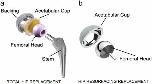
A hip implant is an artificial medical mobility device that connects the femur to the pelvis (Merola & Affatato, Citation2019). It consists of four components namely stem, femoral head, acetabular cup, and backing cup. The stem is connected to the femoral head which in turn is connected to the acetabular cup, together they act as a ball and socket joint, therefore, allowing unrestricted motion in all degrees of freedom (i.e. flexion, extension, abduction, adduction, internal rotation, and external rotation). The acetabular cup fits into the backing cup, thus, completing the assembly of the hip implant as shown in . (English et al., Citation2016; Chethan et al., Citation2021).
Figure 1. Main components of a Hip Implant (Mattei et al., Citation2011).
For selecting the materials there are two main requirements. Biological requirements mainly deal with the biocompatibility of the materials, and mechanical requirements deal with wear resistance, stress concentration, stability of the implant (Fiorentino et al., Citation2013; Bennett, Citation2008). The materials most commonly used in a hip implant are Cobalt-chromium alloys, Titanium alloys, stainless steel, and UHMWPE (Chethan, Zuber et al., Citation2019; Atar, Citation2013). These materials are used as they are compatible with humans and can be replaced by natural hip joints.
The major problem with the hip implants which are previously used was the disintegration of the metallic implant into metal ions which would result in the implant becoming harmful, causing adverse reactions in the body (Ihaddadene et al., Citation2011). Biomaterials that are currently used possess better mechanical properties and are biocompatible, thus generating lesser wear (Chethan et al., Citation2020; Iglič et al., Citation2002).
Recent studies mainly focus on design and analysis to determine various parameters (such as stress, wear rate, strain, deformation, etc.) to avoid the early failure of the hip implant. An analysis is performed using the finite element method using different loads as per ASTM standards (ASTM, Citation2015; Colic et al., Citation2016). Several studies have been carried out to improve the performance of implants. (Chethan, Zuber et al., Citation2019) determined the best suitable cross-section of a hip implant. They evaluated different designs of the stem (circular, ellipse, oval, trapezoidal) with a different set of materials (UHMWPE, CoCrMo alloy, and Ti-6Al-4 V alloy). The analysis showed that CoCrMo alloy was preferred for stem design and trapezoidal-shaped stem design showed the least deformation and stress. (Milovanović et al., Citation2020) to determine the fatigue crack growth, stress, and strain of the hip implant using Ti-6Al-4 V extra low interstitial alloy. The analysis showed the variation of stress with the thickness (maximum stress increased as thickness reduced) and the maximum stress was found at the neck. The highest stress states were located on and in the vicinity of the crack.
(Jawahir et al., Citation2016) studied that cryogenics of biomedical implants. Effect of cryogenics on the performance, quality, and sustainability of implants are studied. Their results concluded that cryogenics increased the wear resistance, surface hardness, and corrosion resistance of the surface, and it is also a non-toxic alternative to the conventional method of machining.
Some works focus on the interaction of the implant with different sets of materials (Chethan, Zuber et al., Citation2019; Göktaş et al., Citation2022). In the current work, a circular cross-shaped stem is considered, and FEM analysis was carried out by varying the diameter of the femoral head for two different sets of materials using ANSYS R-19. Femoral head sizes majorly depend on the anatomy of an individual which usually varies from 24 mm to 54 mm. In the study, a range of sizes from 24 mm to 48 mm has been taken based on previous studies (Cetin & Sofuoglu, Citation2018; Sofuoglu & Cetin, Citation2015; Celik et al., Citation2022). This work helps to understand the effect of change in the femoral head size and the best materials combination for the hip implant.
2. Material and methods
In the current study, two different sets of materials were considered. In the first set, Ti-6Al-4 V was selected as the material for the backing Cup, UHMWPE for the acetabular cup, CoCr for the femoral head, Ti-6Al-4 V for the stem of the implant. In the second set of materials considered, CoCr was selected as the material for the backing cup, UHMWPE for the acetabular cup, CoCr for the femoral head, CoCr for the stem of the implant (Mihalcea et al., Citation2021; Messellek et al., Citation2017; Atar, Citation2013). The circular cross-shaped stem with a total length of 180 mm is considered. Mechanical properties of the materials are given in .
Table 1. Material properties (Kadam et al., Citation2011; Chethan, Shyamasunder Bhat et al., Citation2019)
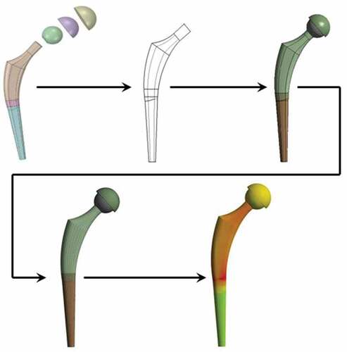
The models were designed using CATIA. The size of the acetabular cup and backing cup was kept constant at a value of 6 mm and 4 mm respectively (Al-hamad et al., Citation2014; Goebel et al., Citation2013; Liu et al., Citation2006). For the femoral head, the diameter was varied from 24 mm to 48 mm. The analysis was conducted at a gap of 4 mm starting from 24 mm up to 48 mm (Cho et al., Citation2016; Tsikandylakis et al., Citation2018; Cross et al., Citation2012).This analysis was done on both sets of materials mentioned earlier. The models developed were imported to ANSYS R-19 Workbench and the analysis was carried out. From the analysis, the values of equivalent stress, equivalent strain, and total deformation were noted. The frontal view of the stem is shown in .
Figure 2. Frontal view of the hip stem used in the study.
2.1. Meshing and boundary conditions
For the analysis, the unstructured mesh was used. For selecting the mesh size, separate trial analyses were conducted in which the mesh size was varied from 1 mm to 0.3 mm at intervals of 0.1 mm. A hip implant with a 36 mm femoral head is considered for the mesh grid independence study. From the results of the analyses, it was found that there was not a large variation in the values of stresses below 0.5 mm. So, in all the models the mesh is considered as 0.5 mm. The mesh grid independence study is shown in .
Figure 3. Mesh grid Independence.
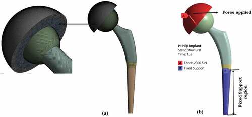
For the analysis, the loading conditions were taken as per ISO 7206–4:2010 (E). A resultant force of 2300 N (1800 N in X direction and −1420 N in Y direction) was applied on the surface of the backing cup and the bottom part of the stem was kept fixed in all degrees of freedom. shows the meshed file and the boundary condition applied to the implant.
Figure 4. (a) Meshing of the implant, (b) Boundary conditions and application of force on the implant.
2.2. Frictional properties
For the current study, contact behavior is considered as frictional contact. The values of coefficient of friction for the first set of materials were 0.18 for the interaction between the backing cup and the acetabular cup and 0.15 between the acetabular cup and the femoral head, and 0.2 between the femoral and the stem.
The values of coefficient of friction for the second set of materials were 0.23 for the interaction between the backing cup and the acetabular cup, 0.23 between the acetabular cup and the femoral head, and 0.21 between the femoral head and the stem surface (Duong et al., Citation2010; Huang et al., Citation1999; Saldívar-García & López, Citation2005). With these conditions, static structural analysis was performed for both the set of materials.
3. Results
Static structural analysis was conducted on the implant with femoral head sizes ranging from 24 mm to 48 mm. The values of equivalent stress, equivalent strain, and the total deformation were analysed and tabulated for each set of materials considered for the current study. . Shows the various values of stress, strain, and deformation for both sets of materials.
Table 2. Values of equivalent stress, equivalent strain, and the total deformation
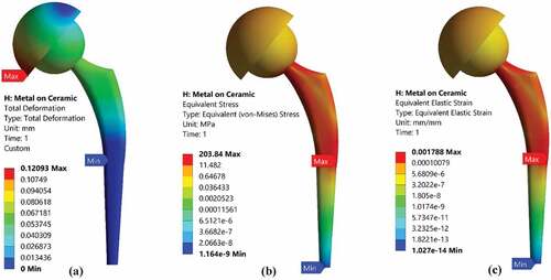
For the first set of materials, the backing cup was made of Ti-6Al-4 V, an acetabular cup of UHMWPE, femoral head of CoCr, and stem of Ti-6Al-4 V. Stress values varied from 218.13 MPa to 203.84 MPa as femoral head diameter was increased. The highest equivalent stress was observed for the femoral head diameter of 24 mm, and the lowest equivalent stress was observed for the femoral head diameter of 48 mm. Total deformation and equivalent strain also had a similar variation (Values decreased with increase in femoral head diameter). shows the stress, strain, and deformation for femoral head diameter of 48 mm.
Figure 5. (a) Total deformation, (b) equivalent stress, (c) equivalent strain of the Hip Implant with 48 mm femoral head diameter.
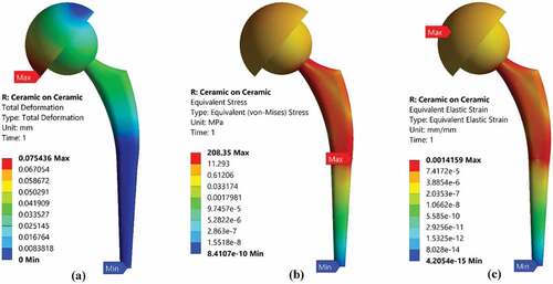
For the second set of materials, the backing cup was made of CoCr, an acetabular cup of UHMWPE, femoral head of CoCr, and stem of CoCr. Stress values varied from 222.78 MPa to 208.35 MPa as femoral head diameter was increased. The highest equivalent stress was observed for the femoral head diameter of 24 mm, and the lowest equivalent stress was observed for the femoral head diameter of 48 mm. Total deformation and equivalent strain also had a similar variation (Values decreased with an increase in femoral head diameter). shows the stress, strain, and deformation for femoral head diameter of 48 mm.
The maximum stress for all the models, for both sets of materials, is found on the middle portion of the stem, as shown in . Similarly, the maximum strain for all the models, for both sets of materials is found on the Acetabular Cup, as shown in , and the total deformation for all the sizes, for both sets of materials, is found on the backing cup, as shown in .
Figure 6. (a) Total deformation, (b) Equivalent stress, (c) Equivalent strain of the Hip Implant with 48 mm femoral head diameter.
4. Discussion
In today’s world, a lot of work has been done in the field of total hip arthroplasty for both in-vitro and in-vivo implants. There are several designs available from these studies that have improved the development of implants, both modular as well as non-modular designs. In a modular design, the neck is not directly connected to the stem. It is connected to the stem with the help of a coupling, hence allowing a wider range of modifications according to the requirements. Whereas in a non-modular design, the neck is directly connected to the stem, hence acting as one unit (Affatato, Citation2014a). The most commonly used materials for Hip Implants are titanium alloys, stainless steel, Cobalt-chromium alloys, high-strength alloys, ceramics, and polymers. Nowadays, various techniques are implemented to deduce a combination of these materials, thus, providing the best output, and enhanced life of the implant (Affatato, Citation2014b). Other studies showed that titanium alloys, Cobalt chromium alloys have better material characteristics than, stainless steel, etc. Thus, for the current study, circular stem design (Chethan, Zuber et al., Citation2019; K.N Chethan et al., Citation2020) with a material combination of Ti-6Al-4 V, CoCr and UHMWPE was considered (Colic et al., Citation2016; Desai et al., Citation2015; Saikko et al., Citation1993). To determine the mesh size, a separate set of trial analyses was conducted. The main focus of this trial analysis was to determine the variation of the parameters with a primary focus on the variation of stress. The mesh size was then selected when the variation of stress was minimal with respect to its corresponding mesh size. The values of the coefficient of friction of the different contact surfaces were then documented (Duong et al., Citation2010; Huang et al., Citation1999; Saldívar-García & López, Citation2005).
A study conducted by (Kluess et al., Citation2007), where the material for the model was selected as UHMWPE for different femoral Head sizes, i.e. 28 mm, 32 mm, 36 mm, and 40 mm. The resultant force acting on the hip joint was 1288 N in two degrees of freedom. The study showed that the maximum stress was found for the model with a femoral head size of 28 mm with a value of 3.25 MPa, and the minimum stress was found for the model with a femoral head size of 40 mm with a value of 1.25 MPa. Thus, arriving at the conclusion that, as the femoral head diameter was increased, the value of maximum stress decreased. Another study conducted by (Taylor et al., Citation2013) showed a maximum von Mises stress of 729 MPa for femoral head diameter of 48.2 mm, and it showed a minimum von Mises stress of 580 MPa for femoral head diameter of 45.6 mm. The Femoral Head was made of CoCr and the stem was made of Ti-6Al-4 V. A force of 1852 N was applied on the surface of the femur. (Oshkour et al., Citation2014), the maximum principal stress in the stem was found to be 76.7 MPa for a circular cross-section, similarly, the minimum principal stress was found to be 51.3 MPa for a trapezoidal cross-section, both models having a constant stem length of 179.77 mm. The applied force in the study was 3000 N on the head, and 1250 N on the side of the femur (lateral). (Anguiano-Sanchez et al., Citation2016) aimed at determining the variation of von Mises stress by applying a coating of PEEK over a stem that was made of Ti-6Al-4 V. They found that by applying a force of 3000 N on the model, the maximum equivalent stress was found to be 181.14 MPa. The FEM analysis showed that there was an increase in the load transfer with the PEEK coating as compared to without the coating. It also showed an increase in the load transfer as the thickness of the coating increased. (Vogel et al., Citation2021) examined two types of implant, i.e. cemented and uncemented implant, and calculated the maximum von Mises stress for each type. For the implant made of PEEK, the maximum von Mises stress ranged from 32 MPa for cemented to 33.8 MPa for the uncemented implant. Similarly, for a CoCr implant the von Mises ranged from 52.9 MPa for uncemented to 52.0 MPa for cemented.
In the current study, the maximum stress value for Ceramic-on-Ceramic for femoral head diameter of 24 mm was 222.78 MPa. Similarly, the maximum stress value was 218.13 MPa for metal on ceramic for femoral head diameter of 24 mm. Therefore, comparing these two values for the two different sets of materials, Metal-on-Ceramic material combination (Ti-6Al-4 V, UHMWPE, CoCr,) showed a lower Maximum Stress as compared to the maximum stress for Ceramic-on-Ceramic material combination (CoCr, UHMWPE, CoCr).
4.1. Limitations of the current study
This work it is tried to analyse the effect of the change in femoral head size in the hip implant. The backing cup and acetabular cups sizes are kept constant. A static load is applied to the hip implant as it is impossible to consider an exact load acting in the hip implants. However, it can be estimated that the effect of change in femoral head sizes in hip implants. In this study moments acting on the implants are not considered and also the joint reaction force. These two parameters can be considered in a future study to investigate further. In hip implants wear is a predominant factor that leads to a revision of hip implants. An average of 52.4% of hip implants is subject to revision due to wear (Burger et al., Citation2007; Chethan et al., Citation2018; Ulrich et al., Citation2008). So, the better-performed hip implant from the study can be further investigated to estimate the wear rate in the interfaces. Along with this, there is a need to consider the realistic loads acting on hip implants like running, walking, and stair climbing (Williams, Citation2013; Van Den Bogert et al., Citation1999). Also, these implants can be subjected to analysis along with femur bone. So, all the above-said analyses can be performed using finite element analysis and also in vivo studies to validate the results obtained from the finite element analysis.
5. Conclusion
In the current study, two sets of analyses are performed for two different material combinations between Ti-6Al-4 V, CoCr, and UHMWPE. These materials are widely used currently in hip implants due to their superior biomechanical properties. The circular cross-shaped stem with change in femoral head sizes from 24 mm to 48 mm is used for analysis. The acetabular cup and backing cup thickness are kept constant throughout the study. The size of the acetabular cup and backing cup is considered 6 mm and 4 mm respectively. Loading and boundary conditions are considered as per the ASTM standards. It was observed that the material combination of Ti-6Al-4 V for stem and a backing cup of CoCr and acetabular cup of UHMWPE showed lesser von Mises stress in all the femoral head sizes combinations over CoCr for stem and a backing cup of CoCr and acetabular cup of UHMWPE. It was also observed that with an increase in femoral head diameter, the maximum stress value decreased. Hip implant with Ti-6Al-4 V for stem and a 4 mm backing cup of CoCr and 6 mm acetabular cup of UHMWPE shown the least stress value of 203.48 MPa over all the other models which are used in the analysis. However in larger prospects, if we compare the material combinations there is a 1% variation in stress values with change in materials used for stem between Ti-6Al-4 V and CoCr keeping all other combinations constant. So practically both materials can be used for the total hip prosthesis and also there is a need to carry out in vitro experimental studies to validate the results obtained in current work.
Abbreviations
ASTM - American Society for Testing and Materials
CoCrMo alloy - Cobalt-chromium-molybdenum alloy
FEM - Finite element method
PEEK - Polyether Ether Ketone
Ti-6Al-4V alloy - Alpha-beta titanium alloy
THA - Total Hip Arthroplasty
UHMWPE - Ultra-high molecular weight polyethylene
Authors’ contributions
Kavish Maulik Shah: Visualization, Writing – review & editing, Investigation.
Aniket Kunal Bhawe: Writing – review & Investigation.
N. Shyamasunder Bhat: Project administration, Writing – review & editing.
B Satish Shenoy: Project administration, Visualization, Writing – review & editing.
Chethan K N: Project administration, Visualization, Writing – review & editing, Investigation.
All authors reviewed and approved the final manuscript before submitting it to the journal.
Consent for publication
All authors consent to the publication of this manuscript.
Acknowledgements
The authors thank the Department of Aeronautical and Automobile Engineering, Manipal Institute of Technology, Manipal Academy, Manipal for providing the computational facility to carry out this research.
Disclosure statement
No potential conflict of interest was reported by the author(s).
Additional information
Funding
Notes on contributors
Chethan K N
Dr. Chethan K N working as Assistant Professor-Senior Scale in the Department of Aeronautical and Automobile Engineering, Manipal Institute of Technology, Manipal Academy of Higher Education, Manipal, Karnataka, INDIA. He holds B.E. (Mechanical Engineering), M.Tech (Manufacturing Engineering & Technology) and Ph.D. (Computational Biomechanics) degrees. He has a more than Nine years of teaching and research experience. His area of interest includes Biomechanics of the hip joint, Finite element analysis of biomedical implants, Composite materials, and Manufacturing of medical implants. The author has published several articles in reputed journals related to finite element analysis of hip implants, mechanical characterization of materials, and composite materials.
References
- Affatato, S. (2014a). Contemporary designs in total hip arthroplasty (THA). Perspectives in Total Hip Arthroplasty, 46–13. https://doi.org/10.1533/9781782420392.1.46
- Affatato, S. (2014b). The history of biomaterials used in total hip arthroplasty (THA). Perspectives in Total Hip Arthroplasty, 19–36. https://doi.org/10.1533/9781782420392.1.19
- Al-hamad, M., Duff, J. M., Takamura, K. M., & Amstutz, H. C. (2014). Acetabular component thickness does not affect mid-term clinical results in hip resurfacing. Clinical Orthopaedics and Related Research, 472(5), 1528–1534. https://doi.org/10.1007/s11999-014-3468-2
- Anguiano-Sanchez, J., Martinez-Romero, O., Siller, H. R., Diaz-Elizondo, J. A., Flores-Villalba, E., & Rodriguez, C. A. (2016). Influence of PEEK coating on hip implant stress shielding: A finite element analysis. Computational and Mathematical Methods in Medicine, 2016(March), 1–10. https://doi.org/10.1155/2016/6183679
- ASTM. (2015). Standard practice for finite element analysis (FEA) of non-modular metallic orthopaedic hip femoral stems 1. In Astm. (Issue August 2013). ASTM International. https://doi.org/10.1520/F2996-13.Copyright
- Atar, E. (2013). Sliding wear performances of 316 L, Ti6Al4V, and CoCrMo alloys, Kovove Mater. 183–188.
- Bennett, D. (2008). Materials & design finite element analysis of hip stem designs. Materials & Design. 291, 45–60. https://doi.org/10.1016/j.matdes.2006.12.014
- Burger, N. D. L., de Vaal, P. L., & Meyer, J. P. (2007). Failure analysis on retrieved ultra high molecular weight polyethylene (UHMWPE) acetabular cups. Engineering Failure Analysis, 14(7), 1329–1345. https://doi.org/10.1016/j.engfailanal.2006.11.005
- Celik, E., Alemdar, F., Bati, M., Dasdemir, M. F., Buyukbayraktar, O. A., Chethan, K. N., Kara, M., & Mihçin, Ş. (2022). Mechanical investigation for the use of polylactic acid in Total Hip Arthroplasty using FEM analysis (pp. 17–23). Springer. https://doi.org/10.1007/978-3-030-86297-8_2
- Cetin, M. E., & Sofuoglu, H. (2018). A statistical approach to explore cemented total hip reconstruction performance. Australasian Physical and Engineering Sciences in Medicine, 41(1), 177–188. https://doi.org/10.1007/s13246-018-0627-x
- Chethan, K. N., Ogulcan, G., Bhat, N. S., Zuber, M., & Shenoy, B. S. (2020). Wear estimation of trapezoidal and circular shaped hip implants along with varying taper trunnion radiuses using finite element method. Computer Methods and Programs in Biomedicine, 196(1), 105597. https://doi.org/10.1016/j.cmpb.2020.105597
- Chethan, K. N., Satish Shenoy, B., & Shyamasunder Bhat, N. (2018). Role of different orthopedic biomaterials on wear of hip joint prosthesis: A review. Materials Today: Proceedings, 5(10), 20827–20836. https://doi.org/10.1016/j.matpr.2018.6.468
- Chethan, K. N., Shyamasunder Bhat, N., Zuber, M., & Satish Shenoy, B. (2019). Finite element analysis of different hip implant designs along with femur under static loading conditions. Journal of Biomedical Physics and Engineering, 9(5), 507–516. https://doi.org/10.31661/jbpe.v0i0.1210
- Chethan, K. N., Shyamasunder Bhat, N., Zuber, M., & Satish Shenoy, B. (2021). Finite element analysis of hip implant with varying in taper neck lengths under static loading conditions. Computer Methods and Programs in Biomedicine, 208(1), 106273. https://doi.org/10.1016/j.cmpb.2021.106273
- Chethan, K. N., Zuber, M., Bhat, N. S., Shenoy, B. S., & Kini, R. C. (2019). Static structural analysis of different stem designs used in Total Hip Arthroplasty using finite element method. Heliyon, 5(6), e01767. https://doi.org/10.1016/j.heliyon.2019.e01767
- Chethan, K. N., Zuber, M., Bhat, N. S., & Shenoy, B. S. (2020). Optimized trapezoidal-shaped hip implant for Total Hip Arthroplasty using finite element analysis. Cogent Engineering, 7(1), 1–13. https://doi.org/10.1080/23311916.2020.1719575
- Cho, M.-R., Choi, W. K., & Kim, J. J. (2016). Current concepts of using large femoral heads in Total Hip Arthroplasty. Hip & Pelvis, 28(3), 134. https://doi.org/10.5371/hp.2016.28.3.134
- Colic, K., Sedmak, A., Grbovic, A., Tatic, U., Sedmak, S., & Djordjevic, B. (2016). Finite element modeling of hip implant static loading. Procedia Engineering, 149(June), 257–262. https://doi.org/10.1016/j.proeng.2016.06.664
- Cross, M. B., Nam, D., & Mayman, D. J. (2012). Ideal femoral head size in Total Hip Arthroplasty balances stability and volumetric wear. HSS Journal, 8(3), 270–274. https://doi.org/10.1007/s11420-012-9287-7
- Desai, C., Hirani, H., & Chawla, A. (2015). Life estimation of hip joint prosthesis. Journal of the Institution of Engineers (India): Series C, 96(3), 261–267. https://doi.org/10.1007/s40032-014-0159-4
- Duong, C.-T., Nam, J.-S., Seo, E.-M., Patro, B. P., Chang, J.-D., Park, S., & Lee, -S.-S. (2010). Tribological property of the cobalt—chromium femoral head with different regions of wear in total hip arthroplasty. Proceedings of the Institution of Mechanical Engineers, Part H: Journal of Engineering in Medicine, 224(4), 541–549. https://doi.org/10.1243/09544119JEIM709
- English, R., Ashkanfar, A., & Rothwell, G. (2016). The effect of different assembly loads on taper junction fretting wear in total hip replacements. Tribology International, 95(1), 199–210. https://doi.org/10.1016/j.triboint.2015.11.025
- Fiorentino, A., Zarattini, G., Pazzaglia, U., & Ceretti, E. (2013). Hip prosthesis design. Market analysis, new perspectives and an innovative solution. Procedia CIRP, 5(1), 310–314. https://doi.org/10.1016/j.procir.2013.01.061
- Goebel, P., Kluess, D., Wieding, J., Souffrant, R., Bader, R., Heyer, H., & Sander, M. (2013). The influence of head diameter and wall thickness on deformations of metallic acetabular press-fit cups and UHMWPE liners: A finite element analysis. Journal of Orthopaedic Science, 18(2), 264–270. https://doi.org/10.1007/s00776-012-0340-7
- Göktaş, H., Subaşi, E., Uzkut, M., Kara, M., Biçici, H., Shirazi, H., Chethan, K. N., & Mihçin, Ş. (2022). Optimization of hip implant designs based on its mechanical behaviour. Lecture Notes in Networks and Systems, 328 LNNS(1), 37–43. https://doi.org/10.1007/978-3-030-86297-8_4
- Huang, P., Salinas-Rodriguez, A., & López, H. F. (1999). Tribological behaviour of cast and wrought Co-Cr-Mo implant alloys. Materials Science and Technology, 15(11), 1324–1330. https://doi.org/10.1179/026708399101505284
- Iglič, A., Kralj-Iglič, V., Daniel, M., & Maček-Lebar, A. (2002). Computer determination of contact stress distribution and size of weight bearing area in the human hip joint. Computer Methods in Biomechanics and Biomedical Engineering, 5(2), 185–192. https://doi.org/10.1080/10255840290010300
- Ihaddadene, R., Affatato, S., Zavalloni, M., Bouzid, S., & Viceconti, M. (2011). Carbon composition effects on wear behaviour and wear mechanisms of metal-on-metal hip prosthesis. Computer Methods in Biomechanics and Biomedical Engineering. 14(August), 33–34. https://doi.org/10.1080/10255842.2011.591623
- Jawahir, I. S., Puleo, D. A., & Schoop, J. (2016). Cryogenic machining of biomedical implant materials for improved functional performance, life and sustainability. 46(1), 7–14. https://doi.org/10.1016/j.procir.2016.04.133
- Kadam, M., Gupta, M., Sivaprasad, P. V., Kumar, G. S., & Wijk, O. (2011, March). International Conference of World-Class Technology in Materials and Manufacturing. Modelling and finite element analysis of stress distribution in total hip replacement using different material combinations M & MT 2011 M & MT 2011.
- Kluess, D., Martin, H., Mittelmeier, W., Schmitz, K. P., & Bader, R. (2007). Influence of femoral head size on impingement, dislocation and stress distribution in total hip replacement. Medical Engineering and Physics, 29(4), 465–471. https://doi.org/10.1016/j.medengphy.2006.07.001
- Liu, F., Jin, Z., Roberts, P., & Grigoris, P. (2006). Importance of head diameter, clearance, and cup wall thickness in elastohydrodynamic lubrication analysis of metal-on-metal hip resurfacing prostheses. Proceedings of the Institution of Mechanical Engineers, Part H: Journal of Engineering in Medicine, 220(6), 695–704. https://doi.org/10.1243/09544119JEIM172
- Lunn, D. E., Lampropoulos, A., & Stewart, T. (2016). Basic science - Basic biomechanics of the hip. Orthopaedics and Trauma, 30(3), 239–246. https://doi.org/10.1016/j.mporth.2016.04.014
- Mattei, L., Di Puccio, F., Piccigallo, B., & Ciulli, E. (2011). Lubrication and wear modelling of artificial hip joints: A review. Tribology International, 44(5), 532–549. https://doi.org/10.1016/j.triboint.2010.06.010
- Merola, M., & Affatato, S. (2019). Materials for hip prostheses: A review of wear and loading considerations. Materials, 12(3), 495. https://doi.org/10.3390/ma12030495
- Messellek, A. C., Ouali, M. O., Benabid, Y., Amrouche, A., & Beloulla, A. (2017). Design optimization and material selection of acetabular component of hip prosthesis using computational concepts. Computer Methods in Biomechanics and Biomedical Engineering, 20(sup1), 131–132. https://doi.org/10.1080/10255842.2017.1382896
- Mihalcea, E., Vergara-Hernandez, H. J., Jimenez, O., Olmos, L., Chavez, J., & Arteaga, D. (2021). Design and characterization of Ti6Al4V/20CoCrMo−highly porous Ti6Al4V biomedical bilayer processed by powder metallurgy. Transactions of Nonferrous Metals Society of China (English Edition), 31(1), 178–192. https://doi.org/10.1016/S1003-6326(20)65486-3
- Milovanović, A., Sedmak, A., Grbović, A., Mijatović, T., & Čolić, K. (2020). Design aspects of hip implant made of Ti-6Al-4V extra low interstitials alloy. Procedia Structural Integrity, 26(2019), 299–305. https://doi.org/10.1016/j.prostr.2020.06.038
- Oshkour, A. A., Osman, N. A. A., Bayat, M., Afshar, R., & Berto, F. (2014). Three-dimensional finite element analyses of functionally graded femoral prostheses with different geometrical configurations. Materials and Design, 56(1), 998–1008. https://doi.org/10.1016/j.matdes.2013.12.054
- Ramos, A., Relvas, C., Completo, A., & Simo, J. A. (2012). The strain distribution for the natural and implanted hip joint articulation. Computer Methods in Biomechanics and Biomedical Engineering, 15(September), 363–364. https://doi.org/10.1080/10255842.2012.713603
- Saikko, V. O., Paavolainen, P. O., & Slätis, P. (1993). Wear of the polyethylene acetabular cup: Metallic and ceramic heads compared in a hip simulator. Acta Orthopaedica, 64(4), 391–402. https://doi.org/10.3109/17453679308993653
- Saldívar-García, A. J., & López, H. F. (2005). Microstructural effects on the wear resistance of wrought and as-cast Co-Cr-Mo-C implant alloys. Journal of Biomedical Materials Research - Part A, 74(2), 269–274. https://doi.org/10.1002/jbm.a.30392
- Sanfilippo, J. A., & Austin, M. S. (2006). Implants for total hip arthroplasty, 3(6), 769–776. https://doi.org/10.1586/17434440.3.6.769.
- Sofuoglu, H., & Cetin, M. E. (2015). An investigation on mechanical failure of hip joint using finite element method. Biomedizinische Technik, 60(6), 603–616. https://doi.org/10.1515/bmt-2014-0173
- Taylor, P., George, S. P., & Kumar, G. S. (2013). Virtual and Physical Prototyping Patient specific parametric geometric modelling and finite element analysis of cementless hip prosthesis Patient specific parametric geometric modelling and finite element analysis of cementless hip prosthesis This paper p. November 2014, 3(1), (pp. 37–41). https://doi.org/10.1080/17452759.2012.755654
- Tsikandylakis, G., Mohaddes, M., Cnudde, P., Eskelinen, A., Kärrholm, J., & Rolfson, O. (2018). Head size in primary total hip arthroplasty. EFORT Open Reviews, 3(5), 225–231. https://doi.org/10.1302/2058-5241.3.170061
- Ulrich, S. D., Seyler, T. M., Bennett, D., Delanois, R. E., Saleh, K. J., Thongtrangan, I., Kuskowski, M., Cheng, E. Y., Sharkey, P. F., Parvizi, J., Stiehl, J. B., & Mont, M. A. (2008). Total hip arthroplasties: What are the reasons for revision? International Orthopaedics, 32(5), 597–604. https://doi.org/10.1007/s00264-007-0364-3
- Van Den Bogert, A. J., Read, L., & Nigg, B. M. (1999). An analysis of hip joint loading during walking, running, and skiing. Medicine & Science in Sports & Exercise, 31(1), 131–142. https://doi.org/10.1097/00005768-199901000-00021
- Vogel, D., Wehmeyer, M., Kebbach, M., Heyer, H., & Bader, R. (2021). Stress and strain distribution in femoral heads for hip resurfacing arthroplasty with different materials: A finite element analysis. Journal of the Mechanical Behavior of Biomedical Materials, 113(1), 104115. https://doi.org/10.1016/j.jmbbm.2020.104115
- Williams, P. T. (2013). Effects of running and walking on osteoarthritis and hip replacement risk. Medicine & Science in Sports & Exercise, 45(7), 1292–1297. https://doi.org/10.1249/MSS.0b013e3182885f26