
 ?Mathematical formulae have been encoded as MathML and are displayed in this HTML version using MathJax in order to improve their display. Uncheck the box to turn MathJax off. This feature requires Javascript. Click on a formula to zoom.
Abstract
Design and manufacturing process activities of a product require different software applications for facilitating to test of replicas without the need for a physical model. Practically, CAE (computer-aided engineering) software can be used for simulation analysis with FEM (finite element method) and other engineering programs. This study was undertaken to analyze the CAD (computer-aided design) file of a homogeneous rough surface model that can be integrated into CAE software (i.e. ABAQUS) with reduced file size. The rough surface of the static contact model for CAE software analysis was presented in different file formats, namely; solid part (*.sldprt), IGES (*. igs), STEP (*.stp), Parasolid part (*.x.t), and ACIS (*sat) files. The comparative analysis of each file for the static contact model was performed from CAD file, ODB (Open Document Database) file, and CAE file. The obtained file formats did not result in any difference in the geometry of the surface model. Among file formats present, using a typical Parasolid part file for simulations of static rough surfaces seemed to be superior by generating the smallest size files. The results of the study would add knowledge for enhancing CAD interoperability with the CAE program.
PUBLIC INTEREST STATEMENT
Computer-aided design or engineering (CAD/CAE) with the finite element method (FEM) may help in designing and manufacturing a product. Using CAD/CAE enables designers to develop the concept of constructing a complicated object into various simple pieces (blocks), or by dissecting the object into a smaller part. The CAD solid surface provides a model at both macro- and micro- or nano-levels with a precise dimension as required for the CAE application. The present work analyzed the different file formats of the point cloud in the computer-aided design (CAD) software for transferring into the CAE program. The use of CAD data exchange of Parasolid XT in the study generated files serving as a superior program with reduced file size. This finding may add to the knowledge of interoperability CAD/CAE software for the improvement of design and manufacturing products.
1. Introduction
Recently, varying CAx systems such as CAD/CAE have been efficiently developed to facilitate technological revolutions in product design (Berselli et al., Citation2020). In particular, CAD can generate articles of a product-shaped model by defining or selecting parameters and constraints (Chaparala et al., Citation2013; Hadj et al., Citation2018; Ramnath et al., Citation2020). Moreover, objects represented in CAD data with the full parameters can be enhanced before transferring of design intent into other CAx systems. Specifically, CAE system based-computer software can be applied for improving product design and resolving engineering problems in many industrial sectors. This system may serve for simulating, optimizing, and validating designs, products, and manufacturing processes that can be integrated with computer-aided manufacturing (CAM). Correspondingly, CAE technologies provide a precise model for supporting engineers during the design process (Chaparala et al., Citation2013). For instance, CAE simulations present multi-body analysis (MBD), and deflection and stress analysis using finite element method (FEM), simulating the actuation system, or performing optimization studies. Accordingly, virtual models of CAE provide benefits of integrating various data and supporting product testing, compared to physical testing (Chaparala et al., Citation2013).
In practice, products of biomedical implants such as artificial hips and knees could be modeled and simulated for their contact surfaces with the usage of FEM existing in CAE software (Kartini et al., Citation2018). Particularly, these contact surfaces have a homogeneous rough surface at a micro-scale, which can be generated using mathematical equations available in MATLAB. It was demonstrated previously that developing an algorithm could be implemented by changing in 3D-topography of surface micro-geometry at the level of asperity using image processing techniques of both artificial and real surfaces for 3D-CAD models (Sloetjes et al., Citation2002).
Since CAD systems have powerful electronic files for print, machining, or other manufacturing operations, it may be beneficial to add the CAD models containing files into some operating systems. Correspondingly, the stored files of the informant system could be written and subsequently changed into the data and the entity map data by converting them to the system of destiny. Here, the CAD model should describe mathematically for a physical and geometric object. These descriptions may include algorithms and numerical data and in the prescription of the geometry of the object. In these geometry descriptions, the CAD system provides the tools to create, transmit, and manipulate the file formats (Field, Citation2004).
Conventionally, CAD systems have also filed-based storage structures (Kim & Han, Citation2003). Using CAD software for designing a geometrical product can save files in several types of formats (solid parts, Parasolid, STEP, IGES, and ACIS files). These typical files can be transferred into the CAE software. Due to the CAD interoperability of models with CAE software, the signed algebraic levels in the Boundary-representative (B-rep) model could be recognized within a discretized domain of the geometric accuracy of the surface and be kept according to the original representation of NURBS (Upreti & Subbarayan, Citation2017). At this case, CAD and CAE have the capability for integration or cooperation with each other (Hong et al., (Citation2003); Park Hong & Dang, Citation2010). However, the CAD-CAE integration system for automation and optimization of the design processes has not been fully realized (Hong et al., (Citation2003); Park Hong & Dang, Citation2010; Sun et al., Citation2007).
On the other hand, generating 3D models of existing objects involve point clouds with a large collection of points expressed as Cartesian coordinates (X, Y, Z) could be acquired by 3D laser scanners or other technologies. These point cloud files can assist the CAD process by providing a real model of objects. Also, 3D modeling with point cloud files provides powerful tools for storing and using spatial data. Furthermore, 3D models of these data points could be manipulated into CAD software (Park Hong & Dang, Citation2010), which generally became an extension file compatible with IGES (*.iges) with the FEM software.
In cases of static contact surfaces models, the ABAQUS software can be used for FEM simulations. The previous work suggested that the rolling contacts could be modeled using a two-dimensional (2D) in which the rigid cylinders roll pushed on an artificial rough surface (Ismail & E. Saputra, Citation2014; Ismail et al., Citation2013). In the current experiment, however, the rolling surface contacts for FEM simulation purposes were examined for the ball acting upon the 3D-rough surface, and the simulation of the severity of the contact was performed under three normal forces (Ismail et al., Citation2013).(Lipman & Lubell, Citation2015)
Further, there is a limitation to using FEM simulation of a contact surface if a ball-normal force acts upon it. This restriction could be solved with an alternative solution (Ismail & E. Saputra, Citation2014). For this reason, the distribution of the contact surface could be manipulated by changes in surface topography. In this case, three models of the rough surface had been proposed and presented in other file formats. Consequently, this file format resulted in the smallest file size that could be reported in percentage increments from the stationary phase entry phase (Anggoro et al., Citation2017; Ismail et al., Citation2012). Instead, the highest accuracy of the geometric model for the homogeneous rough surfaces could be obtained by the curve wizard method towards enhancing the interoperability process of CAD and CAE models (Kartini et al., Citation2018; Md & Rezwana, Citation2021).
This study presents a processing approach for the CAD model with the point cloud files in varying formats that can be implemented into the CAE software. For this purpose, 5 (five) different file formats of the homogeneous rough surface were acquired from the CAD software, namely; solid parts, Parasolid (x*t), IGES (igs. file), STEP (stp. file), and ACIS file (sat.). These formats were then transferred through ABAQUS software for simulations in CAE software. Here the parameters examined in data transferability included the size of files generated from CAD, CAE, and the Open Document Database (ODB) programs. Results are expected to get an insight into how the domain for mutual dependency CAD and CAE programs influence both the design and the overall product development process.
2. Background and theory
2.1. Data transfers of CAD model
Data transfers of CAD model represent for exchanging data between different CAD systems and to downstream applications of CAx systems. Moreover, the CAD data exchange may include direct model translation, neutral file exchange, and third-party translators (Chang, Citation2014). Typically CAD data transfers are focused on geometric products covering wireframes, surfaces, solids, and drawings. Yet other targets of transferring CAD data may involve metadata (non-graphical attributes). Additionally, the CAD data content covers model targets (history trees, formulas, rules, guidelines), while the usage data may include Numerical Control tool paths, Geometric dimensioning, and tolerancing (GD&T), process planning, and assembly structure. Instead, the exchanging process of CAD data files involves varying the life cycle of the product. Accordingly, the first stage of the design process is focused on data exchange of pieces of information on the geometry and design targets, afterward with metadata and application data (Sergej et al., Citation2015).
2.2. CAD data exchange preferences
The first option for CAD data exchange relates to the direct model translation, for which the data file stored in a product database can translate directly in one step from any CAD system format to others. Typically, a neutral database may translate data directly and its structure must be universal, generated by the least prerequisite designations of varying modeling data, and be the impartial format of supplier software (Xu, Citation2009). In this case, using options such as File Open and File Save As can read and/or write other CAD systems such as SolidWorks, PTC Creo, Siemens NX, and CATIA (Chang, Citation2014). However, this choice is often restricted because most CAD formats are privately owned by suppliers. Accordingly, these direct translators may have unidirectional, partially functional, and un-standardized CAD formats (Choi et al., Citation2002; Kim et al., Citation2019)
On the other hand, the neutral file exchange may be used for translating data within CAD systems based on intermediary neutral format. This method uses the original CAD data by embedding a preprocessor root into the system along with the generation of the neutral file. After processing the neutral file, its format can be converted into the target native formats (Choi et al., Citation2002; Kim et al., Citation2019). Here, neutral formats (e.g., IGES, and STEP) are commonly used by standards organizations, but other branded software packages are still available, even considered as quasi-industry standards.
Further, many files with neutral formats according to their proprietary formats are available as follows: IGES (Initial Graphics Exchange Specification); DXF (Drawing exchange Format); VDA-FS (Verband der Automobilindustrie-Flächenschnittstelle); PDES (Product Data Exchange Specification); STEP (ISO 10303-Standard for the exchange of product model data); and Parasolid XT. Moreover, the CAD data translator from many software packages may be employed for reading and/or writing from other CAD systems into other CAD formats. Correspondingly, these translators may have owned functions, for which the machine translator requires one or both of the CAD packages installed with code (APIs) for reading/writing the data. Additionally, low-level toolkits can be employed for importing or exporting software code for the usage of CAD.
For enhancing the quality of product data, a great concern has been made by avoiding intrinsic and extrinsic problems during CAD data exchange. This condition can be achieved by simplifying the integration of downstream applications in the design sequence. Accordingly, the product data quality may relate to intrinsically (CAD model structure) and extrinsically problems of these issues appearing during translation. In this case, a STEP file has been developed for another CAD system to solve the extrinsic problems controlling parameters of 2-D and 3-D models, and history-based modeling.
2.3. The proposed solid models
This present work used various computer software to generate a rough surface 3D model containing point cloud files which were stored using spatial data. Each software was used in the study involving MATLAB processing with Gaussian Height Distribution (GHD), CAD Solidworks processing, and ABAQUS processing of CAE as shown in the flow diagram (). Each running of the FEM simulation of the contact surface was performed in different software. The resulting data from the simulation was then recorded and presented in the different file formats. Later, MATLAB processed three models of GHD and the resulting data are shown in . This visual image was transferred to Solidworks processing and resulted in a point cloud with parametric dimensions of a, b, c, and d on each model, and then stored in 5 (five) different file formats. Instead, the CAD file size was examined for the image on Solidworks processing which was transferred to ABAQUS processing to save with file extension similar to Solidworks processing. In this way, ODB and CAE file size were evaluated with the same software.
Figure 1. Flowchart at each stage of the research process.
3. Materials and method
The file data was processed in the study involving Gaussian Height Distribution; Creation of cloud point, Cloud point generation, Determination of point cloud, Exporting point cloud, and ABAQUS software processing.
3.1. Generating gaussian height distribution
In this work, a rough surface arithmetic model of 3D point cloud was expressed with an extension file (*. XYZ). The artificial models of the rough surface were created by MATLAB using mathematical equations of two variations corresponding to the homogeneous Gaussian height distribution Equationequations (1)(1)
(1) as follows;
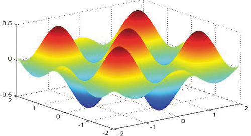
where: a represents the size of the curve’s peak, b is location of the midpoint of the peak, and c denotes the standard deviation, called the Gaussian RMS controlling “bell” width. shows the rough surfaces of the 3D point cloud obtained from MATLAB software with the Gaussian height distribution (GHD) equation, which contains several variables (Sun et al., Citation2007).
Figure 2. The point cloud resulting from MATLAB.
3.2. Creating a set of data cloud point
When using 3D data, for example, for 3-D printing, surface models of 3D point clouds were required. The 3D point clouds were subsequently transformed into a 3D mesh with the help of modeling software, yielding the model for employing CAD software. In this present study, the Gaussian distribution of the height (GHD) in MATLAB software was adopted for the rough surface model, including the set of data point clouds (), while the plotting of the point clouds from CAD processing is shown in .
Figure 3. Point cloud resulting from CAD.
3.3. Generating the point clouds
The next step in rough surface modeling was to determine mathematical expressions in MATLAB to generate 3D shape/object in CAD software. The resulting point clouds were generated by the extension *.Xyz () and then taken to the next determination process. After generating the point clouds, the determination of the geometry was performed before continuing with the next process. The resulting geometry was subsequently plotted with MS*Excel program or from the computer display of the point clouds. The dimensional parameters (a, b, c, and d) of the rough surface were determined as shown in . The results of the point cloud geometry are presented in .
Figure 4. Dimensional (a, b, c, d) geometric modelling.
Table 1. Determined data point cloud
3.4. Exporting solid models
The obtained point cloud files with five different formats could be exported for solid modeling with other file formats. These five file formats consisted of the solid piece part (*.sldprt), IGES (*.iges), Parasolid part (*.x.t), ACIS (*.sat), and STEP (*.stp) files, which were subsequently processed in the ABAQUS software.
3.5. Processing by ABAQUS
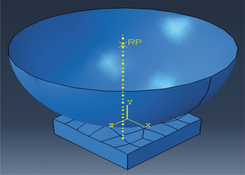
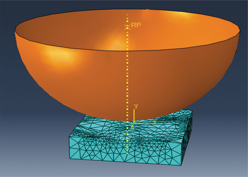
The ABAQUS software is a powerful program for Computer-Aided Engineering (CAE). Stages in ABAQUS processing included importing files for respective measurements of geometry in ABAQUS, determination of the material assembly, determination of the type of contact, and generating the mesh. In the first stage, the solid surface was modeled and pre-processed in the ABAQUS, which was integrated into CAE 6 program (Ismail et al., Citation2013; Sloetjes et al., Citation2002). The subsequent stage could produce the solid modeling file with five extensions acquired by clicking on the toolbar menu. shows the shape of solid surface examined in the present study.
Figure 5. Solid surface produced from ABAQUS software.
Further, the imported file of a surface model was generated by the toolbar menu as shown in . The next stage was to post-process the imported results for each file so that comparative data analysis between the software and the manual measurements could be carried out. This stage was done by clicking on the “Tools” menu; followed by clicking on “Consult” as shown in . By selecting menu options of “Distance” can provide a distance between the longest point and wider foot to be scanned. After following the stages above, the value in the text box below stated “Distance: 243.214824 components … ” () showing that distance was determined. Accordingly, the parametric dimensions of a, b, c, and d could be determined (). Here, the same resulting parameter values for a, b, c, and d are presented in five files (*.sldprt;*.sat; *.iges; *.x.t; *.step) to be 0.499, 0.499, 1.24, 2.499 mm, respectively.
Figure 6. Visual menu in ABAQUS program.
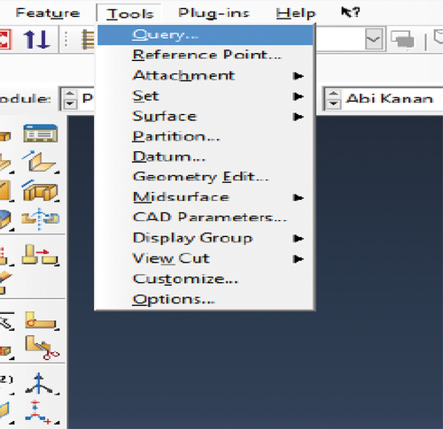
Figure 7. The measured data resulted from ABAQUS Program.
The next stage was to input the material model of aluminum 1060 having characteristics of Young’s modulus (E) of 6900 MPa and Poisson’s Ratio of 0.33. Moreover, the assembly material model with a penetrator was drawn with the rigid indenter and discrete sphere having a radius of 4 mm, while the surface model is penetrated under normal load where the position of the penetrator is perpendicular above the surface ().
Figure 8. Assembly of surface solid model.
For FEM analysis, the type of surface contact was first defined. In this way, the typical node-to-surface interaction was selected, while the boundary conditions in the model were determined to be analyzed by assigning an Encast/Fix lock. In the analysis, the penetrator was allowed to move down along the y-axis 0.5 mm, corresponding to the depth of indentation of 0.5 mm (). Moreover, the meshing of the surface model was performed to determine the mesh size, the number of ingredients, and the type of element ().
Figure 9. FEM with boundary condition.
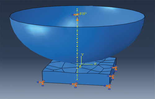
Figure 10. FEM meshing.
4. Results and discussion
After running FEM analysis using the ABAQUS software, output visual files of the model could be produced. In addition to CAD files also included the large generated CAE files and the large ODB files generated with the Gaussian rough surface model 1 (). Additionally, other Gaussian models (model 2 and model 3) with the equal wavelength were simulated and compared, while the resulting data from the simulation are presented in .
Table 2. Varying file size obtained from transfer file of surface model 1
Table 3. Varying file size obtained from transfer file of surface model 2
The results of the three models of Gaussian surface roughness in the simulation processes were compared and presented in . The three models of Gaussian roughness that have been developed, and then saved as files. These files were examined for the effect on the CAD file size for five types of files, namely (* sldprt), (* igs), (* stp), (* xt), and (* sat), presented in the CAE file size and the ODB file size. The CAD file size is related to the size of imported files from MATLAB to CAD, while CAE file size corresponding to the size imported from CAD to ABAQUS. The ODB file size relates to the size generated from the running process of the simulation.
Table 4. Varying file size obtained from transfer file of surface model 3
present file formats with the extensions of *.sldprt, *.sat, *.iges, *.x.t, *.step corresponding to file size obtained from CAD, CAE, and ODB processes. presents the type file size obtained during the transferring data of MATLAB into CAD. It is shown that the third model Gaussian of the surface roughness has the highest file size among all types of files. Here the type file has the smallest file size (*.xt), while the biggest size of the file is the type (*.sldprt).
Figure 11. CAD file size for the three Gaussian rough surface model.
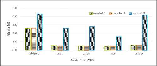
Figure 12. CAE files size for three models of Gaussian rough surface.
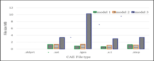
However, all three Gaussian models for rough surfaces show that .sldprt file type could not be transferred from CAD to ABAQUS. Out of the three Gaussian models on the transferring process from CAD to ABAQUS, .iges file type requires the highest file size, whereas .xt file type requires the lowest file size (). Likewise, for all three Gaussian models of the rough surface, the ODB file size () is similar to the CAE file size (). Here file (*.sldprt) could not be transferred from CAD to ABAQUS and could not be saved in the ODB file. It is obvious that the file type (*.iges) requires the highest file size and the lowest file size is needed for (*.xt) file type.
Figure 13. ODB file size of three models of the Gaussian rough surface.
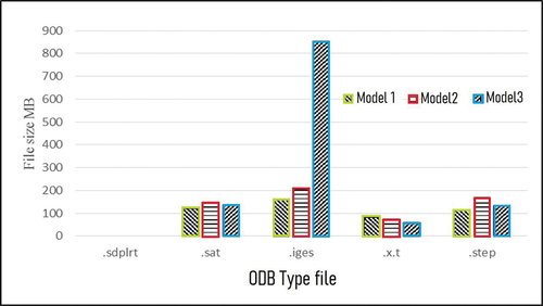
The results of file type comparisons could be made by the percentage comparison of file size. It was found that the largest size corresponded to the file type (*.iges), while the smallest file size related to file (*.xt) for each model. The comparative percentage can be seen in . The smallest percentage in model 3 of Parasolid type is 57%. In this type of Parasolid, the ODB file size has much smaller than that in the (*.iges) file (6%). Therefore, this file is more efficient for storing the output visual file.
Table 5. Comparative percentage of the various file type of model 1 [(*.xt) vs (*.iges)]
Table 6. Comparative percentage of the various file type of model 2 [(*.xt) vs (*.iges)]
Table 7. Comparative percentage of the various file type of model 3 [(*.xt) vs (*.iges)]
From an output result point of view, using Parasolid for exporting the 3D CAD models provided a reduced file size compared to that of other file formats. This is because the Parasolid software is supported by the hybrid models, containing both B-Rep and mesh geometry. Correspondingly Parasolid can store complex B-Rep models with a solid, sheet, wireframe, mixed, and even non-manifold topology. With this file, a full range of CAD operations with any type of model is provided for the designer. Accordingly, the Parasolid file can capture high-detailed information for 3D CAD models with both precise and meshed surfaces.
5. Conclusion
The three Gaussian models of the rough surfaces were built and stored in five different file formats namely *.sldprt, *.iges, *.step, *.x.t, and *.sat. Those file formats were then examined for their effects on CAD file size, CAE file size, and ODB file size. It can be concluded that:
Among the three file formats, the ODB file format required the largest file size. The lowest file size was obtained with the ODB file corresponding to the (*. xt) file extension. In contrast, the highest file format was obtained corresponding to the (*.iges) file type. The (*.xt) file format has the lowest file size, suggesting that the (*.xt) file format is the most effective file type to store the data. Moreover, the (*.xt) file extension may provide a more effective computation process, in which the faster computation time may relate to the lower file size. The study demonstrated the type of Parasolid file that provided superior storage for simulations of static rough surfaces with output CAD, CAE, and ODB file size. The largest file size on average of 57% could be obtained using the Parasolid file format. Accordingly, the Parasolid file is recommended for transferring geometric CAD data of homogeneous rough surfaces into CAE software.
Acknowledgements
This work is part of research funded by Diponegoro University under contract, to the Research Publication International (RPI) Grant-No: 185-91/UN7.6.1/PP/2021. High appreciation also goes to Universitas Pembangunan (UPN) “Veteran” Jawa Timur for providing the Ph.D. scholarship.
Disclosure statement
No potential conflict of interest was reported by the author(s).
Additional information
Funding
Notes on contributors
A.P. Bayuseno
K. Kartini received Ph.D. in Mechanical Engineering from Diponegoro University, Indonesia. The focus of the research was conducted on the study of software engineering, especially on the design and construction of micro and macro surface roughness software and FEM.
G. A Sipayung finished a Bachelor of Engineering (BE) from the Department of Mechanical Engineering, Diponegoro University. The focus of his research is to design and construct, micro surface roughness by software.
R. Ismail is a senior lecturer at the Department of Mechanical engineering, Diponegoro University. His research interests cover many aspects of tribology and surface properties of biomedical materials.
J. Jamari is a Professor in Mechanical Engineering, at Diponegoro University. Research interest covers many aspects of material design, surface treatment, including wear characterization and lubrication technology.
A. P. Bayuseno is a Professor in Material Science and Engineering at Diponegoro University, Indonesia. Research interest covers many aspects of ceramics design, applied crystallography, including materials characterization and waste processing.
References
- Anggoro, P. W., Saputra, E., Tauviqirrahman, M., Jamari, J., & Bayuseno, A. P. (2017). A 3-dimensional finite element analysis of the insole shoe orthotic for foot deformities. International Journal of Applied Engineering Research, 12 (15) , 5254–14 0973-4562 d o i: 37622/000000.
- Berselli, G., Bilancia, P., & Luzi, L. (2020). Project-based learning of advanced CAD/CAE tools in engineering education. International Journal on Interactive Design and Manufacturing (Ijidem), 14(3), 1071–1083. https://doi.org/10.1007/s12008-020-00687-4
- Chang, K.-H. (2014). Product design modeling using CAD/CAE. Academic Press.
- Chaparala, R. T., Hartman, N. W., & Springer, J. (2013). Examining CAD Interoperability through the use of ontologies. Computer-Aided Design and Applications, 10(1), 83–96. https://doi.org/10.3722/cadaps.2013.83-96
- Choi, G.-H., Mun, D.-H., & Han, S.-H. (2002). Exchange of CAD part models based on the macro-parametric approach. International Journal of CAD/CAM, 2 (1), 13–21 http://cde.kr/ .
- Field, D. A. (2004). Education and training for CAD in the auto industry. Computer-Aided Design, 36(14), 1431–1437. https://doi.org/10.1016/j.cad.2003.10.007
- Hadj, R. B., Belhadj, I., Gouta, C., Trigui, M., Aifaoui, N., & Hammadi, M. (2018). An interoperability process between CAD system and CAE applications based on CAD data. International Journal on Interactive Design and Manufacturing (Ijidem), 12(3), 1039–1058. https://doi.org/10.1007/s12008-017-0445-5
- Hong, S. P., Lee, G. B., & Kim, H. (2003). Collaborative engineering system supporting product. ASME Design Engineering Technical Conferences sept 2-6, 2003 Chicago, Illinois, USA, Vol. 1: 873–880 doi:10.1115/DETC2003/CIE-48267
- Ismail, R., & E. Saputra, M. (2014). Tauviqirrahman and J.Jamari. Modeling of repeated rolling contact on rough surface: Surface topographical change. Advanced Materials Research, 896 (0) , 642–645. https://doi.org/10.4028/www.scientific.net/AMR.896.642
- Ismail, R., Tauviqirrahman, M., Jamari, & Schipper, D. J. 2012. The observation of the steady state phase on rolling contact using finite element analysis. American Institute of Physics (AIP) Conference Proceeding Sept 23-25, 2011 Bali, Vol. 1415: 136–139.
- Ismail, R., Tauviqirrahmana, M., Saputra, E., Jamari, J., & Schippera, D. (2013). Modeling of repeated rolling contact of rigid ball on rough surface: Residual stress and plastic strain analysis. Procedia Engineering, 68 (0) , 593–599. https://doi.org/10.1016/j.proeng.2013.12.226
- Kartini, K., Saputra, E., Ismail, R., Jamari, J., & Bayuseno, A. (2016). Analysis of the contact area of smooth and rough surfaces in contact with sphere indenter using finite element method. MATEC Web of Conferences Oct. 15-17 Bali, 58.
- Kartini, K., Sipayung, G. A., Saputra, E., Ismail, R., Jamari, J., & Bayuseno, A. P. 2018. The use of curve wizard method for generating rough surface in CAD model and data transferring analysis in CAE model. Proceding IEEExplore Nov. 24-25, 2017 Malang, 978-1-5386-2182-0/17IEEE (273-277).
- Kim, J., & Han, S. (2003). Encapsulation of geometric functions for ship structural CAD using a STEP database as native storage. Computer-Aided Design, 35(13), 1161–1170. https://doi.org/10.1016/S0010-4485(03)00020-4
- Kim, Y., Lee, H., Safdar, M., Jauhar, T. A., & Han, S. (2019). Exchange of parametric assembly models based on neutral assembly constraints. Concurrent Engineering: Research and Applications, 27(4), 285–294. https://doi.org/10.1177/1063293X19869047
- Lipman, R., & Lubell, J. (2015). Conformance checking of PMI representation in CAD model STEP data exchange files. Computer-Aided Design, 66 (c) , 14–23. https://doi.org/10.1016/j.cad.2015.04.002
- Md, T. H. K., & Rezwana, K. S. (2021). A review of CAD to CAE integration with a hierarchical data format (HDF)-based solution. Journal of King Saud University - Engineering Sciences, 33(4), 248–258. https://doi.org/10.1016/j.jksues.2020.04.009
- Park Hong, S., & Dang, X. P. (2010). Structural optimization based on CAD–CAE integration and metamodeling techniques. Computer-Aided Design, 42 (10) , 112–126 doi:10.1016/j.cad.2010.0603.
- Ramnath, S., Haghighi, P., Venkiteswaran, A., & Shah, J. J. (2020). Interoperability of CAD geometry and product manufacturing inion for computer integrated manufacturing. International Journal of Computer Integrated Manufacturing, 33(2), 116–132. https://doi.org/10.1080/0951192X.2020.1718760
- Sergej, B., Abdul, S., Josip, S., & Ken, T. (2015). Advances in parameterized CAD feature translation: Transdisciplinary lifecycle analysis of systems. In Advances in Transdisciplinary Engineering (Vol. 2). Delft: IOS Press 615–624 doi:10.3233/978-1.61499-544-9-615 .
- Sloetjes, J. W., Tasan, J. C., De Roou, M. B., & Schipper, D. J. (2002). Algorithm for determining 3D changes in micro-geometry using image processing techniques. Proceedings of The Second Asia International Conference on Tribology Malaysia, Vol. 10: 251–252.
- Sun, J., Frazer, J. H., & Minngxi, T. (2007). Shape optimisation using evolutionary techniques. Computer & Industrial Engineering, 53(2), 200. https://doi.org/10.1016/j.cie.2007.06.010
- Upreti, K., & Subbarayan, G. (2017). Signed algebraic level sets on NURBS surfaces and implicit Boolean compositions for isogeometric CAD–CAE integration. Computer-Aided Design, 82 (C) , 889–902. https://doi.org/10.1016/j.cad.2016.09.006
- Xu, X. (2009). Integrating advanced computer-aided design, manufacturing, and numerical control: Principles and implementations. Information Science Reference.