
 ?Mathematical formulae have been encoded as MathML and are displayed in this HTML version using MathJax in order to improve their display. Uncheck the box to turn MathJax off. This feature requires Javascript. Click on a formula to zoom.
Abstract
This article highlights a comparison and classification of six algorithms for extracting reference currents used in the context of harmonic compensation for the case of a TLC hybrid filter on a stochastic electrical network. With the ultimate goal of determining the most robust and reliable algorithm, the electrical network presents four variable configurations such as, operation in sinusoidal and balanced voltage, sinusoidal and unbalanced voltage, balanced and disturbed voltage, or even in unbalanced voltage and disrupts. Firstly, a presentation of these six algorithms or methods identified in the time domain will be made with injections of the fifth-order harmonics taken in positive sequences during the execution or compilation of the six algorithms for the four network operating hypotheses. And in a second step, a cross-comparison of the performances on the basis of indicators such as the THD (harmonic distortion rate) and UFI (unbalance factors) required by the IEEE 519–2014 and EN 50160 standard, then a cross-validation is based on some results available in the literature. These results will now facilitate the choice of the most appropriate algorithm depending on the nature of the electrical network in force according to the case studies.
PUBLIC INTEREST STATEMENT
The quality of electrical energy is positioned as a determining factor in the industrial, economic, and social development of several countries in the world and in this case in the case of Cameroon and Chad. This is why the optimization of harmonic depollution on a stochastic three-phase electrical network occupies an important place in this article. It is therefore a question of comparing the performance of several algorithms for extracting reference currents under complex conditions and very close to the industrial world (by associating external and varied disturbances) during depollution or harmonic compensation processes, all combined with a hybrid filter. For the sole purpose of optimizing online harmonic depollution by choosing and implementing the most suitable algorithm according to the characteristics of the electrical network in force at the end of the study, the results obtained in this work will contribute to increasing the lifespan and production capacities of electrical systems in general and especially in the industrial sector.
1. Introduction
The proliferation of non-linear loads is growing exponentially with technological evolution. In general, energy electronics receive special attention for several researchers and engineers at the level of harmonic contamination for harmonic power systems, which are at the origin of the degradation of the power factor, the overheating and the complete destruction of equipments, the errors in the measurements with the instruments, the breakdown of the capacitors (Akagi et al., Citation1999). In order to reduce the harmonic currents, the standard IEEE 519 − 2014 was adopted. The overall harmonic distortion must be at most 5% of the initial value before filtering (Kim & Akagi, Citation1999). Therefore, the current 5% THD limit has always been the performance target that all researchers and designers do their best to achieve. In order to deal directly with harmonic problems and to respect the 5% limits, conventional passive harmonic filters are applied. However, due to their major weaknesses of bulky sizes and patch mitigation tools, innovative harmonic mitigation tools and efficient hybrid filters, combining passive and active models are being developed to replace them. In addition, the development of hybrid filters is also being spurred by the emergence of power semiconductor switching devices such as insulated gate bipolar transistors (IGBTs), thyristor and the availability of powerful controllers such as processors and digital signals (DSP; Shu et al., Citation2022). On the other hand, the success of the compensation or filtering process depends on the reliability and robustness of the algorithm for extracting the reference currents while knowing that the current control laws that cannot act correctly when the network is disturbed and unbalanced in tension. Based on this observation, the aim of this work is to provide a solution to this problem by the comparative evaluation of the techniques for extracting the reference currents. This paper presents the review of six control strategies (original pq, modified pq, pq pseudo mapping matrix, pqr, NFp-q and DCAP methods) for operating conditions in sinusoidal and balanced voltage, sinusoidal and unbalanced voltage, voltage balanced and disturbed, or in unbalanced and disturbed tensions, with the ultimate goal of determining the most suitable method in the event of disturbances.
2. Reference current extraction algorithms
2.1. The P-Q method ON A 4-wire network
The original p-q theory is defined by a transformation of the electrical quantities of coordinates a, b, c into coordinates α, β, 0. A homogeneity exists between the powers expressed in the two coordinates. This method is based on the notion of instantaneous active power P (t) and reactive power q (t), which is the originality of the method (Marini et al., Citation2019) as shown in .
Figure 1. Functional diagram to extract the reference current based on the original p-q method (CitationHarrison).
With and
, the neutral unbalance voltage and current in the reference a, b, c,
are the homopolar in the coordinates a, b, c. The zero sequence voltage and the current in the coordinates α, β, 0, are given by:
The transformation in the orthogonal coordinate system α, β, 0 of the current of a three-phase system are
In addition, the tension is:
With is the Concordia transformation matrix defined by:
In this theory for a four-wire application, we consider that the zero sequence circuit is independent of the circuit in the coordinate, we define two active powers P0 and Pαβ in addition to reactive power qαβ. The total instantaneous active power is defined as the sum of the two active powers and the instantaneous reactive power is the same for the 3-wire p-q system (“IEEE Recommended Practice and Requirements,” Citation2014; Mistry & Patel, Citation2017; Shu et al., Citation2022)
Or,
The powers in the reference α, β, 0 are expressed as below:
Currents in the system α, β, 0 are given as
The reference currents as a function of the powers to be compensated are expressed as follows:
Once the reference currents in the coordinate α, β, 0, are calculated, the inverse formulation of the matrix by Clark/Concordia gives these currents in the coordinates a, b, c, according to the following relation (Hanna Nohra et al., Citation2019):
2.2. Modified P-Q method on the 4-wire network
This technique explores the Concordia transformation applied to simple source voltage and line currents in order to obtain real, imaginary, and zero sequence instantaneous powers (Dubey et al., Citation2021; Sun et al., Citation2020; Yu & Tao, Citation2016). The direct component must be eliminated by transforming the fundamental component into a direct component and the harmonic component into oscillatory harmonics (Marini et al., Citation2019; Naderipour et al., Citation2018; Shu et al., Citation2022) This principle is as follows: consider simple voltage and line currents
of a three-phase homopolar system. Each block of the current extraction diagram contains an equation as shown in . The Concordia transformation makes it possible to bring a three-phase system from a, b, c ax to α, β, and 0 coordinated as follows:
Figure 2. Functional diagram to extract the reference current based on the modified p-q method (Vardar et al., Citation2009).
From there, we get the real, imaginary, and homopolar powers:
These powers can be expressed as the sum of the direct components and the ripple component as follows:
The load current in the axes α, β, 0:
With
Using 2.30, we get the expression of real and imaginary powers:
The expression of the current in the plane α, β, 0 as a function of the instantaneous power is given by:
Likely equation II.31, equation II.32 becomes
Depending on the function given to the filter, it is possible to compensate the harmonic current and the reactive power or either the harmonic current or the reactive power (Abolfathi et al., Citation2017; Bhople & Rayarao, Citation2018; Chang et al., Citation2006; Hoon et al., Citation2017; Mistry & Patel, Citation2017).
We want to compensate for both at the same time, equation II.23 becomes:
Finally, the reference current is obtained using the inverse Concordia transformation.
2.3. P-Q pseudo-mapping matrix method
The modified p-q method could not compensate for the neutral current because the expression of the zero sequence reference component is not equal to the zero sequence current of the circuit. Then, the author proposes to modify the matrix so that the zero sequence currents and that of the power circuit are equal. This led to the pseudo-mapping matrix method. Powers are defined in the same way and the concept remains defined (Chicco et al., Citation2009; Hernández et al., Citation2011; Li et al., Citation2020; Santos et al., Citation2020; Suresh et al., Citation2011) as shown in .
Figure 3. Functional diagram for extracting the reference current based on the p-q pseudo-mapping matrix method (Kalair et al., Citation2017).
The diagram in figure II.3 shows the extraction of the reference currents, which only changes at the level of equation (II.25) instead of (II.26)
2.4. The P-Q-R method
This method introduced by Kim performs a double transformation, a first transformation of the phase-to-neutral voltage and line currents of the coordinate a, b, c to the coordinate α, 0, then a second transformation of the coordinate α, 0 to coordinate PQR as shown in . Its principle is stated as follows: Consider simple voltage and charging currents
of a three-phase homopolar system (Al-Mawali et al., Citation2011; Andari & Beheshti, Citation2011; Barutçu et al., Citation2019; De Araujo et al., Citation2021; Edri et al., Citation2021; Oliveira et al., Citation2018). The figure below illustrates the identification of the reference currents during harmonic current and reactive power compensation. The equations to be introduced in each block are collected as data as follows:
Figure 4. Functional diagram to extract the reference current based on the method p-q-r (Hanna Nohra et al., Citation2019).
Using the Concordia transformation, we get the two relations asfollows:
The following transformation called p-q-r we give:
Ou et
The instantaneous active and reactive powers are given by the equation below:
This gives us the current in the p-q-r axis expressed by:
Depending on the function assigned to the filter, it is possible to compensate the harmonic current and the reactive energy or one of them at the same time. If we want to compensate the harmonic current and the reactive power, EquationEquation 1(1)
(1) becomes:
What gives the currents in the axes α, β, 0:
Finally, the reference current in the axes a, b, c is obtained by the inverse Concordia transformation
(Bhople & Rayarao, Citation2018).
2.5. The NFP-Q method
This method is based on the p-q theory with a difference that the zero sequence component of the current is separated from the zero sequence power (Andari & Beheshti, Citation2012; Chang & Low, Citation2008; Hu et al., Citation2015; Infield et al., Citation2004; CitationJannesar et al.; Jannesar et al., Citation2019). The zero sequence component is distributed over the three line currents and the compensation is independent of the zero sequence voltage. This method is intended for an equilibrium voltage network as shown in . Now, the system of currents expressed as a function of the quantities in the reference α, 0 in (.35).
Figure 5. Functional diagram to extract the reference current based on the method NFp-q (Hanna Nohra et al., Citation2014).
With
We can then write the currents in the reference a, b, c as:
With this equation, the zero sequence component is separated from the current system. The currents will be treated as in a 3-wire network and we then add the zero sequence component (Hanna Nohra et al., Citation2019).
The reference current becomes:
The current in the reference a, b, c is:
On the basis of this formulation, the zero sequence component is added to the reference currents. The new formulation of the reference current is then:
2.6. The DCAP method
The patented DCAP method proposed (Hanna Nohra et al., Citation2014) is based on the distribution of sinusoidal and balanced currents on the source side and not on the distribution of equal powers in the doubled source. It is developed for a polyphase system. Subsequently, we sought to determine the active sinusoidal currents desired in the source. i_sa(t), which provides a unit power factor with a corresponding voltage even in the event of a disturbed voltage system. However, this sinusoidal current makes it possible to ensure a unit power factor with a disturbed voltage necessarily a linear relationship with the fundamental component. v_f (t) disturbed voltage v (t) as (II.41) as shown in .
Figure 6. Schematic diagram for the extraction of the reference current for the DCAP method (Hanna Nohra et al., Citation2014).
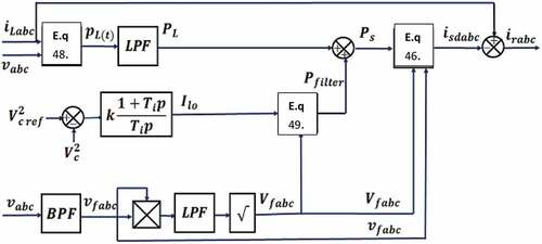
Or Gf is the conductance of the fundamental current and voltage. It should be noted that a sinusoidal current is equivalent to its fundamental component.
The snapshots of the desired sinusoidal currents at the source in phase with their corresponding fundamental voltages are given by:
Finally, by substituting the expression of the voltage in (II.42), the desired active currents at the source become
The fundamental conductance of the polyphase system is:
The system of currents in the phases is obtained as a function of the conductance as follows
By replacing the conductances with their values, it finally allows to see the desired active sinusoidal currents in the source, in phase with their fundamental voltage, and as a function of the total power in the source (Hanna Nohra et al., Citation2019).
The reference currents can simply be deduced from the load currents and the currents in (II.80) noted:
With i = a, b, c the phase index of the three-phase system.
In calculating the power of the load, we do not capture the fundamental components of the voltages. In fact, the instantaneous voltages which exist in the circuit are taken into account. The power of the load is (Akagi et al., Citation1999; Hanna Nohra et al., Citation2014; CitationHarrison; Kalair et al., Citation2017; Kim & Akagi, Citation1999; Padilla-Vento, Citation2021)
is the power absorbed by the filter and required to regulate the DC bus voltage. He expresses himself thus:
The basic concept of compensation in the known methods or already classic algorithms for extracting reference currents consists of distributing the power equally over the three phases in order to balance the currents, which is not valid when the voltage are unbalanced. From these elements, the method (DCAP-Direct Control for Active Power) which is based on another approach for compensation and which makes it possible to formulate the active current (then the reference currents), in a way other than those traditionally used. We have developed thus resulting in a current-balanced system when the network is even highly unfavourable. Thus, the compensation is done in the presence of the negative sequence and zero sequence component of the network. The first author to have developed this new control approach is (Hanna et al, 2018). Subsequently, we sought to determine the desired sinusoidal active current in the source i(t) which ensures a unity power factor with its corresponding voltage v(t) even in the event of disturbance of the voltage system. However, this sinusoidal current making it possible to ensure a unity power factor with a disturbed voltage v(t) therefore has a linear relationship with the fundamental component vf(t) of the disturbed voltage v(t).
3. System modeling
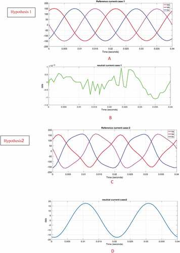
At this level, it is important to recall the spirit of the research in this work by contributing to the classification of the six algorithms for extracting reference currents according to certain indicators. To do so, the electrical system in this article will be studied in four cases of network voltage as shown in :
Hypothesis 1: Sinusoidal and balanced voltage.
Hypothesis 2: Sinusoidal and unbalanced voltage.
Hypothesis 3: Balanced and disturbed voltage.
Hypothesis 4: Unbalanced and disturbed voltage.
Table 1. Digital values of voltage and harmonics
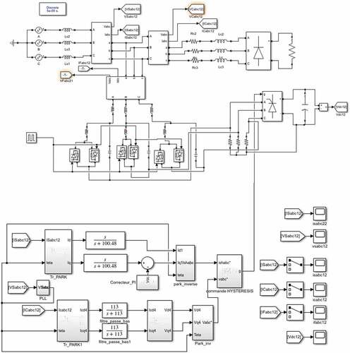
The synoptic of the TLC hybrid filter will as shown in be studied in its four cases with several sought-after objectives which will be developed and commented in our results. On the other hand, the constituted voltage system consists of a fundamental voltage and the harmonic of the order 5, expressed as follows:
Figure 7. Simulink electrical networks with integration of algorithms for extracting reference currents.
With as expressions of the fundamental quantities:
And order 5 harmonic voltages taken in positive sequence as follows:
With is the maximum amplitude of the order harmonic 5.
Table shows the numerical values of the voltage in the four cases studied.
The filter parameters used in the rest of our work have become in the following
Table 2. Parameters of the system to be simulated
4. Result and disscussion
It is important to remember at this level that a fourth connection is made on the neutral wire to observe the behavior of that over time for the four operating hypotheses.
4.1. Original PQ method
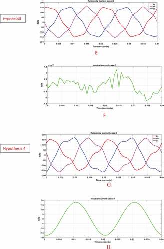
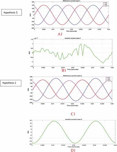
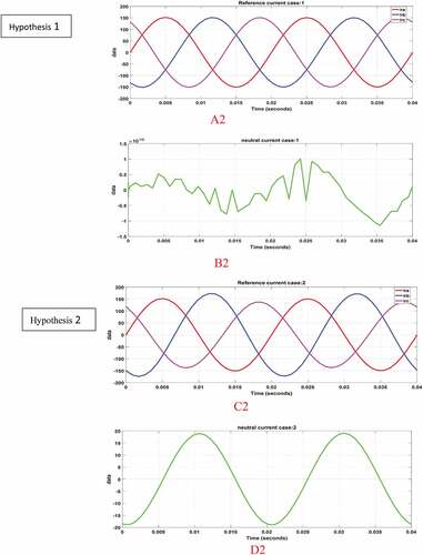
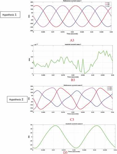
) shows a THD of 1.73% and UFI 0.33% satisfactory results compared to the standard (IEEE 519–2014) for voltage below 69kv, for a THD between 3% and 5%. And the EN 50160 standard which requires an UFI of less than 2%. Hypotheses 2, 3, 4, respectively, present 1.79%; 2%; 0.33% in THD results also in accordance with the standard. On the other hand in UFI boxes 2.3 present respectively 5.33%, 16.66% which are of poor quality with regard to the requirements of the standard above and finally case 4 which offers 1.73% which on the other hand is validated by the standard in force stated above. also shows the evolution of the current in the neutral for each case.
Figure 8. Results with the original PQ method for current (ia, ib,ic) and neutral current for 4 hypothesis (A, B, C, D, E, F, G, H).
4.2. Results with the modified PQ method
shows, respectively, THDs of: 1.73%, 2%, 1.8%, 1.7% for hypothesis 1, 2, 3, 4, which also comply with the IEEE 519–2014 standard; on the other hand, only case 1 has a UFI of 0.33% which also conforms to the standard but cases 2, 3.4 present, respectively, 5%; 8.33% and 3.33%, which are not of good quality in accordance with the standard. Any time on the remark that the modified PQ method succeeded in improving by half the case 3. With a UFI of 8.33%, it seems to be the most indicated method for this hypothesis of functioning.
Figure 9. Results with the modified PQ method for current (ia, ib,ic) and neutral current for 4 hypothesis (A1, B1, C1, D1, E1, F1, G1, H1).
4.3. P-q pseudo-mapping matrix method
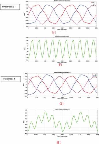
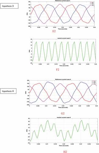
shows THDs of: 1.73%, 2.1%, respectively; 0.33%; 2% for cases 1, 2, 3, 4, which are also satisfactory for the IEEE 519–2014 standard, on the other hand only cases 1, 3 have a UFI of 0.33% and 1.76% which also conforms to the standard but cases 2, 4 show 20%, respectively; 13.76%, which are not of good quality in accordance with the standard. Any time we notice that the pq pseudo-mapping matrix method succeeds in improving box 3 by half better than the first two methods with an UFI of 1.76%. It seems to be the method which ise most suitable for this operating hypothesis.
Figure 10. Simulation p-q pseudo-mapping matrix method for current (ia, ib,ic) and neutral current for 4 hypothesis (A2, B2, C2, D2, E2, F2, G2, H2).
4.4. Simulation results for p-q-r method
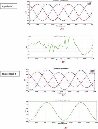
shows, respectively, THDs of: 1.73%, 2.12%; 1.73%; 2.23% for cases 1, 2, 3, 4, which also comply with the IEEE 519–2014 standard; on the other hand, only cases 1 and 3 have a UFI of 0.33% and 0.66%, which also conform to the standard but cases 2 and 4 present 28.33%, and 36.2%, respectively, which are not of good quality in accordance with the standard. Any time on the remark, the PQR method succeeds in improving case 3 with a UFI of 0.66%, it seems to be the most indicated method compared to the first three methods for this working hypothesis.
Figure 11. Simulation results for p-q-r method for current (ia, ib,ic) and neutral current for 4 hypothesis (A3, B3, C3, D3, E3, F3, G3, H3).
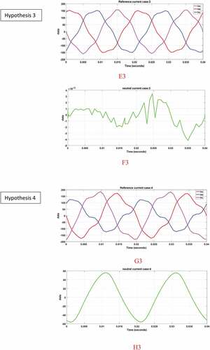
4.5. Simulation results for the NFP-Q theory
shows, respectively, THDs of: 1.73%, 1.95%, 1.74%, 1.95% for cases 1, 2, 3, 4, which also comply with the IEEE 519–2014 standard, on the other hand only cases 1 and 3 have an UFI of 0.33% and 1%, which also comply with the standard but cases 2 and 4 present, respectively, 16.66% and 16.66%, which are not of good quality in accordance with the standard. Any time on the remark that the PQ R method succeeds in improving case 3 with a UFI of 1%, it seems to be the most indicated method compared to the first three methods for this hypothesis operating. But it is also important to note that the PQR method gives us a result of 0.66% UFI, which remains a better result than that obtained with the NFPQ method.
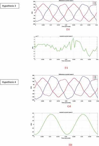
Figure 12. Simulation results for the NFP-Q THEORY for current (ia, ib,ic) and neutral current for 4 hypothesis (A4, B4, C4, D4, E4, F4, G4, H4).
4.6. Simulation results for the DCAP method
shows, respectively, THDs of: 1.73%, 1.73%, 1.73%, and 1.74% for cases 1, 2, 3, and 4, which also comply with the IEEE 519–2014 standard, on the other hand only cases 1, 2, 3, and 4 have an UFI of 0.33%, 0.66 %, 0.66%, 1, respectively, which also conform to the standard. On its own, it succeeds in giving satisfaction for cases 1, 2, 3, and 4 with a better result in case 4 compared to all the methods developed. The DCAP algorithm therefore stands out as being the best for all network operating conditions in this job. The research spirit of this article is to contribute to a classification of six algorithms for extracting reference currents within the framework of harmonic compensation for a stochastic electrical network which for the particular case of this work presents four configurations. A general presentation of all the parameters or indicators is concentrated in a table with the objective also to facilitate the discussion, but above all to validate the results obtained.
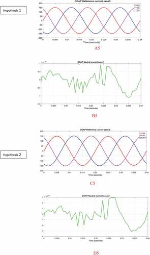
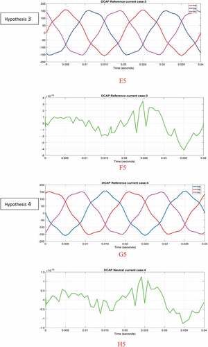
Figure 13. Simulation results for the DCAP theory for current (ia, ib,ic) and neutral current for 4 hypothesis (A5, B5, C5, D5, E5, F5, G5, H5).
5. Validation of results
A double-level validation will be carried out: firstly the IEEE-519-2014 standard will be used as a benchmark, secondly a validation through certain authors such as (“IEEE Recommended Practice and Requirements,” Citation2014) as shown in .
Table 3. Summary table of simulation results
The original PQ method offers 100% satisfaction for the hypotheses (1, 2, 3, and4) in THD, which all comply with the standard (IEEE 519–2014) on the other hand, it is satisfactory at 50% hypotheses (1, 2, 3,4) for the UFI value as shown in . It is better than the modified PQ which offers 25% satisfaction for the UFI value for the hypotheses (1, 2, 3, 4), however we notice that the quality in THD is better for the modified PQ for the hypotheses (1, 2, 3, 4) in comparison with the original PQ. Results are comforted by the work of (LI-WANG et al 2018). The observation is the same for the pq Mapping-matrix method which also offers 50% of UFI for the hypotheses (1, 2, 3, 4) and 100% for the THD being the same assumptions. We can also see that the quality in THD is less good than the first two methods. Results also reassured by the work of (HANNA et al 2018). On the other hand, the NFPQ and PQR methods are at 50% and 100%, respectively, for their THD and common UFI for the hypotheses (1, 2, 3, 4) defined. Finally, the DCAP method which offers 100% satisfaction in THD and UFI for the hypotheses (1, 2, 3, 4), which in the end, appears as the most satisfactory extraction method. These results are supported by the work of (Hanna Nohra et al., Citation2014).
Table 4. Validation table in accordance with IEEE-519-2014
6. Conclusion
In this article, it was a question of making a contribution to the classification of six algorithms for extracting reference currents for harmonic compensation with the TLC hybrid filter under operating conditions in sinusoidal and balanced voltage, sinusoidal and unbalanced voltage, voltage balanced and disturbed. Finally in unbalanced and disturbed tensions with the ultimate goal of determining the algorithm best suited to the disturbances that the electrical network may undergo. Thus, offering the possibility of optimizing the sequence or the compensation step by injection into the electrical network thanks to a robust and reliable extraction algorithm. Harmonic voltage of order 5 taken in positive sequences were used during the execution or compilation of these six algorithms. And it emerges that the algorithm of the DCAP method is positioned as being the extraction technique which resists the most disturbances with results both validated by standard IEEE 519–2014 and EN 50160; on the other hand (Hanna Nohra et al., Citation2014), which in its work with active compensators already presented the advantages of this new approach for extracting reference currents. These results are reinforced in the four operating conditions developed for our case study.
Disclosure statement
No potential conflict of interest was reported by the author(s).
Data availability statement
The data which contributed to the realization of this article are at the same time in the number of the literature but also of the protocols of several experimental tests in laboratories, thus the possible submissions for publications will be made in the days to come. Each time, several data are directly accessible by the following DOI:
doi: 10.1016/j.ijepes.2019.06.020;
doi: 10.1016/j.matcom.2018.07.007;
doi: 10.1016/j.ijepes.2019.105581
doi: 10.1016/j.egypro.2017.11.052.
doi: 10.1016/j.ijepes.2019.105731
Additional information
Funding
Notes on contributors
Luc Vivien Assiene Mouodo
Luc Vivien Assiene Mouodo is a Lecturer in the Engineering Electrical and Department (EED) at Higher Normal School of Technical Education (ENSET) in the University of Douala, Cameroon. He is a PhD student in Electrical and Robotic Energy (EER) Laboratory of modeling Materials and Methods of the National Higher Polytechnic School, Douala University.
Abdel-Hamid Mahamat ALI
Abdel-Hamid Mahamat Ali, is currently working as the director general of l’Institut National Petroleum School of Mao (INSPEM). He has held several positions in the Tchadian government and a researcher at the faculty of exact and applied sciences University of N’Djamena, Tchad.
Jean Gaston Tamba
Jean Gaston Tamba is currently working as an Associate Professor in the University Institute of Technology (IUT) Douala, Cameroon. He received PhD degree in Physics from Yaounde 1 University, Cameroon in 2013.
Thierry Sosso Mayi Olivier
Olivier Sosso Mayi Thierry is currently working as an Associate Professor in the, Higher Normal School of Technical Education Douala University Cameroon. He received PhD degree in Energy Management Systems and Technology fron University of Quebec Three Rivers Canada in 2014. He is head of Electrical Engineering Department at Higher Normal School of Technical Education (ENSET).
References
- Abolfathi, K., Babaei, M., & Ahmarinejad, A. (2017, December). Designing optimal passive filters for transformers under harmonic conditions. Energy Procedia, 141, 411–30. https://doi.org/10.1016/j.egypro.2017.11.052
- Akagi, H., Ogasawara, S., & Kim, H. (1999, October). The theory of instantaneous power in three-phase four-wire systems: A comprehensive approach. In Conference Record of the 1999 IEEE Industry Applications Conference. Thirty-Forth IAS Annual Meeting (Cat. No. 99CH36370) (Vol. 1, pp. 431–439). https://doi.org/10.1109/IAS.1999.799991
- Andari, M. K, & A. A Beheshti. (2012). Pilot based channel estimation in broadband power line communication networks. Communications and Network, 4(3), 240–247. https://doi.org/10.4236/cn.2012.43028
- Al-Mawali, K. S., Sadik, A. Z., & Hussain, Z. M. (2011). Low complexity discrete bit-loading for OFDM systems with application in power line communications. International Journal of Communication Network and System Sciences, 4(6), 372–376. https://doi.org/10.4236/ijcns.2011.46043
- Andari, M. K., & Beheshti, S. A. A. (2011). MAC sub-layer analysis with channel estimation in broadband power line communication. Communications and Network, 3(3), 141–148. https://doi.org/10.4236/cn.2011.33017
- Barutçu, I., Karatepe, E., & Boztepe, M. (2019, December). Impact of harmonic limits on PV penetration levels in unbalanced distribution networks considering load and irradiance uncertainty. International Journal of Electronics and Power Energy System, 118, 105708. https://doi.org/10.1016/j.ijepes.2019.105780
- Bhople, S. U., & Rayarao, S. K. (2018). Comparison of various reference current generation techniques for performance analysis of shunt active power filter using MATLAB simulation. International Journal of Current Engineering and Technology, 6(2): 606–611.
- Chang, G. W., Chu, S. Y., & Wang, H. L. (2006). A new method of passive harmonic filter planning for controlling voltage distortion in a power system. IEEE Transactions on Power Delivery, 21(1), 305–312. https://doi.org/10.1109/TPWRD.2005.852355
- Chang, Y.-P., & Low, C. (2008). Optimization of a passive harmonic filter based on the neural-genetic algorithm with fuzzy logic for a steel manufacturing plant. Experts on System Applications, 34(3), 2059–2070 https://doi.org/10.1016/j.eswa.2007.02.040
- Chicco, G., Schlabbach, J., & Spertino, F. (2009). Experimental assessment of the waveform distortion in grid-connected photovoltaic installations. Solar Energy, 83(7), 1026–1039. https://doi.org/10.1016/j.solener.2009.01.005
- de Araujo, L. R., Penido, D. R. R., & de Souza, B. C. (2021, September). Load composition impacts on the multiple solutions of unbalanced distribution systems. IEEE Transactions on Power Systems, 36(5), 4864–4867. https://doi.org/10.1109/TPWRS.2021.3084448
- Dubey, A., Chandekar, A., & Bopche, M. A preliminary study on harmonics generated by the grid-connected PV system on distribution transformer.pdf.
- Edri, E., Armon, N., Greenberg, E., Moshe-Tsurel, S., Lubotzky, D., Salzillo, T., Perelshtein, I., Tkachev, M., Girshevitz, O., & Shpaisman, H. (2021, August). Laser printing of multilayered alternately conducting and insulating microstructures. ACS Applied Materials & Interfaces, 13(30), 36416–36425. https://doi.org/10.1021/acsami.1c06204
- Hanna Nohra, A. F., Fadel, M., & Kanaan, H. Y. (2019, April). Design of a direct control strategy for a static shunt compensator to improve power quality in polluted and unbalanced grids. Mathematics and Computers in Simulation, 158, 199–215. https://doi.org/10.1016/j.matcom.2018.07.007
- Hanna Nohra, A. F., Kanaan, H. Y., & Fadel, M. (2014, December). A control strategy in active power filter for power quality improvement. In The 2nd IEEE Conference on Power Engineering and Renewable Energy (ICPERE) 2014 (pp. 42–47). https://doi.org/10.1109/ICPERE.2014.7067236
- Harrison, A. The effects of harmonics on power quality and energy efficiency.
- Hernández, J., Ortega, M. J., De la Cruz, J., & Vera, D. (2011, July). Guidelines for the technical assessment of harmonic, flicker and unbalance emission limits for PV-distributed generation. Electric Power Systems Research, 81(7), 1247–1257. https://doi.org/10.1016/j.epsr.2011.03.012
- Hoon, Y., Mohd Radzi, M. A., Hassan, M. K., & Mailah, N. (2017, December). Control algorithms of shunt active power filter for harmonics mitigation: A review. Energies, 10(12), 2038. https://doi.org/10.3390/en10122038
- Hu, H., Shi, Q., He, Z., He, J., & Gao, S. (2015). Potential harmonic resonance impacts of PV inverter filters on distribution systems. IEEE Transactions on Sustainable Energy, 6(1), 151–161. https://doi.org/10.1109/TSTE.2014.2352931
- IEEE Recommended Practice and Requirements for Harmonic Control in Electric Power Systems. (2014 June). In IEEE Std 519-2014 Revis. IEEE Std 519-1992 (pp. 1–29). https://doi.org/10.1109/IEEESTD.2014.6826459.
- Infield, D., Onions, P., Simmons, A. D., & Smith, G. A. (2004). Power quality from multiple grid-connected single-phase inverters. IEEE Transactions on Power Delivery, 19(4), 1983–1989. https://doi.org/10.1109/TPWRD.2004.829950
- Jannesar, M. R., Sedighi, A., Savaghebi, M., Anvari, A., & Guerrero, J. M. (2018). Optimal passive filter planning in distribution networks with nonlinear loads and photovoltaic systems. In 2018 20th European Conference on Power Electronics and Applications (EPE’18 ECCE Europe) (p. 10).
- Jannesar, M. R., Sedighi, A., Savaghebi, M., Anvari-Moghaddam, A., & Guerrero, J. M. (2019, September). Optimal probabilistic planning of passive harmonic filters in distribution networks with high penetration of photovoltaic generation. International Journal of Electrical Power & Energy Systems, 110, 332–348. https://doi.org/10.1016/j.ijepes.2019.03.025
- Kalair, A., Abas, N., Kalair, A. R., Saleem, Z., & Khan, N. (2017). Review of harmonic analysis, modeling and mitigation techniques. Renewable and Sustainable Energy Reviews, 78(7), 1152–1187. https://doi.org/10.1016/j.rser.2017.04.121
- Kim, H., & Akagi, H. (1999, July). The instantaneous power theory on the rotating p-q-r reference frames. In Proceedings of the IEEE 1999 International Conference on Power Electronics and Drive Systems. PEDS’99 (Cat. No. 99TH8475) (Vol. 1, pp. 422–427). https://doi.org/10.1109/PEDS.1999.794600
- Li, P., Jin, W., Li, R., & Guan, M. (2020, February). Harmonics detection via input observer with grid frequency fluctuation. International Journal of Electrical Power & Energy Systems, 115, 105461. https://doi.org/10.1016/j.ijepes.2019.105461
- Marini, A., Ghazizadeh, M., Mortazavi, S., & Piegari, L. (2019, June). A harmonic power market framework for compensation management of DER based active power filters in microgrids. International Journal of Electrical Power & Energy Systems, 113, 916–931. https://doi.org/10.1016/j.ijepes.2019.06.020
- Mistry, R., & Patel, D. A. (2017). Control of shunt active power filter for improvement of power quality. International Journal of Computer Science and Mobile Computing, 6(1), 8.
- Naderipour, A., Abdul-Malek, Z., Miveh, M. R., Hadidian Moghaddam, M. J., Kalam, A., & Gandoman, F. H. (2018, October). A harmonic compensation strategy in a grid-connected photovoltaic system using zero-sequence control. Energies, 11(10), 2629. https://doi.org/10.3390/en11102629
- Oliveira, T., Carvalho, P., Ribeiro, P., & Bonatto, B. (2018). PV hosting capacity dependence on harmonic voltage distortion in low-voltage grids: Model validation with experimental data. Energies, 11, 465.
- Padilla-Vento, P. (2021). Training in social entrepreneurship to generate productive and human capacities Lima, Peru in 2020. Journal of Human Resources and Sustainable Studies, 9(1), 93–105. https://doi.org/10.4236/jhrss.2021.91007
- Santos, E., Khosravy, M., Lima, M. A. A., Cerqueira, A. S., & Duque, C. A. (2020, June). ESPRIT associated with filter bank for power-line harmonics, sub-harmonics and inter-harmonics parameters estimation. International Journal of Electrical Power & Energy Systems, 118, 105731. https://doi.org/10.1016/j.ijepes.2019.105731
- Shu, Q., Fan, Y., Xu, F., Wang, C., & He, J. (2022, January). A harmonic impedance estimation method based on AR model and Burg algorithm. Electric Power Systems Research, 202, 107568. https://doi.org/10.1016/j.epsr.2021.107568
- Sun, W., Yang, L., Zare, F., Xia, Y., Cheng, L., & Zhou, K. (2020, May). 3D modeling of an HVDC converter transformer and its application on the electrical field of windings subject to voltage harmonics. International Journal of Electrical Power & Energy Systems, 117, 105581. https://doi.org/10.1016/j.ijepes.2019.105581
- Suresh, M., Panda, A. K., & Suresh, Y. (2011). Fuzzy controller based 3Phase 4wire shunt active filter for mitigation of current harmonics with combined p-q and Id-Iq control strategies. Energy and Power Engineering, 3(1), 43–52. https://doi.org/10.4236/epe.2011.31007
- Vardar, K., Akpinar, E., & Sürgevil, T. (2009, October). Evaluation of reference current extraction methods for DSP implementation in active power filters. Electric Power Systems Research, 79(10), 1342–1352. https://doi.org/10.1016/j.epsr.2009.04.004
- Yu, G., & Tao, L. (2016). 2m+1 point estimate method for probabilistic harmonic power flow. In 2016 IEEE Power Energy Society on General Meeting PESGM. https://doi.org/10.1109/PESGM.2016.7741657