
 ?Mathematical formulae have been encoded as MathML and are displayed in this HTML version using MathJax in order to improve their display. Uncheck the box to turn MathJax off. This feature requires Javascript. Click on a formula to zoom.
Abstract
In the racing world, weight is one of the key factors when developing a vehicle. Therefore, the aim is to reduce it as much as possible to achieve a good power/weight ratio that can be translated into increased speed, manoeuvrability, or reduced fuel consumption. For this reason, the trend is to redesign existing parts to obtain more optimised and lighter ones using new materials and complex structures that are often manufactured using 3D printing. In this manuscript, a spider or support for the fairing of a racing motorbike was designed, making use of topological optimisation techniques by means of Computer-Aided Design and using additive manufacturing. Specifically, PLA was used as an eco-friendly material to replace the conventional welded metal used in these areas of a motorbike. Theoretical and experimental tests were carried out to confirm the viability of the piece. With the analysis of the topological optimisation, it was possible to manufacture a sustainable, low weight and low cost part, which has never been manufactured before with a polymeric material.Keywords: Topologic, FEM, CAD, PLA, fused deposition modelling, Additive manufacturing
1. Introduction
Motorcycles are made up of numerous elements of different sizes and with different functions. This increases the possibilities for redesign in the racing automotive world. Therefore, by doing the relevant studies, it can be concluded which parts of a vehicle can be replaced by others that offer better performance (Suryatama & Bernitsas, Citation2000). Increasingly, the industry is adopting this approach as they pursue specific objectives that can be achieved through redesign and optimization techniques (Cuong-Le et al., Citation2021; Khatir et al., Citation2019, Citation2021; Khatira & Abdel Wahabb, Citation2019; Tran-Ngoc et al., Citation2021).
Topological optimisation had its origins with A.G. Michell when he published in 1904 “The limits of economy of material in frame-structures”. This is a study in which the author aims to reduce the weight of an articulated bar structure, specifically a cantilever beam, through the use of optimisation methods. It is then that the “Michell beam” is created, which has served as the basis for many of the subsequent analyses of topological optimisation techniques (Paris et al., Citation2010; Stejskal et al., Citation2020).
In 1960, topological optimisation underwent an enormous development, and it was Schmidt who proposed the innovative idea of using digital computation to solve engineering problems, such as obtaining a perfectly functional design assuming reduced cost and minimising constraints. From that moment on, the questions of structural optimisation began to be formulated looking for the minimum weight and with non-linear constraints that limited the acceptable values of displacements and stresses (Norato et al., Citation2007).
Then, in 1988, Bendsoe and Kikuchi developed the SIMP model (Bendsoe & Kikuchi, Citation1988; Bendsoe & Sigmund, Citation2003) where topological optimisation problems began to be tackled with the main idea of maximising the stiffness of the structure. This type of formulation tries to distribute the material within the domain looking for the maximum stiffness, or in other words, the minimum deformation energy, and at the same time reduces the number of non-linear constraints to work with. However, this conditions the operation with different load cases, so that the method of maximum stiffness triggered new problems for the fairing of a racing motorbike whose solution led to refine the discretisation (Biancolini et al., Citation2001; Ehlers & Lachmayer, Citation2020).
Finally, in order to solve the different problems that arose in the framework of topological optimisation, a new formulation is developed, which consists of searching for the minimum weight with constraints in tension by means of the Finite Element Method (FEM; Remache et al., Citation2019).
A process of optimisation, topological or otherwise, of a model involves an iterative redesign (by means of computer-aided design, CAD) to achieve a compromise of the objectives pursued by adapting to a working area. It is therefore important to analyse which parts have possibilities for redesign and/or modification of their materials. In this context, optimisations of different parts have been carried out in different sectors over the last 20 years. There are already several studies on the optimisation of some vehicle parts, especially in aeronautics (Primo et al., Citation2017). Some motorbike parts have also undergone structural optimisation. For example, Lorenzo Scappaticci et al. maximized the performance of a tubular frame designed for a motorcycle racing in the Moto2 category, and minimized the weight of the frame by controlling its stiffness (Scappaticci et al., Citation2017).
The first objective is to reduce the weight of the assembly, so each part is important. Currently, the competition sector is also focusing on the reduction of pollutant emissions associated with combustion, which translates into reduced fuel consumption. A second goal is to reduce the number of components in order to simplify the process of manufacturing and assembling, to save on manufacturing costs by integrating several parts into one. Finally, both industry and competition consider that increasing environmental sustainability is of paramount importance, either by reducing emissions as outlined in the first objective, or by changing the component material to a more environmentally friendly one (Hodonou et al., Citation2019). These 3 purposes presented are the ones that justify the development of this work, and one way to carry them out is to resort to topological optimisation as a technique to obtain a new lighter and less polluting design that satisfactorily fulfils its function.
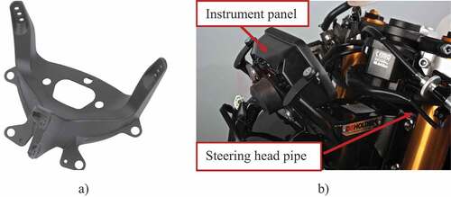
In this work, a fairing support design was developed and topologically optimised using Inspire software. This part has not been optimised to date. Its function is to support the front fairing of the bike and normally hold the headlight and the instrument panel (see )). It is fixed to the motorbike on the chassis, specifically on the steering head pipe (see )). Currently, on the market, most spiders manufactured are made of metal, most commonly aluminium or steel.
Figure 1. (a) Conventional spyder or fairing support. (b) Detail of the installation on a conventional motorbike.
Several basic designs were used to obtain the best performance, and an iterative redesign process was carried out. The aim was to replace the piece with a biodegradable plastic part, polylactic acid (PLA), not only to reduce weight but also to avoid welding and assembly times. The final spider was manufactured by fused deposition modelling (FDM) or Fused Filament Fabrication (FFF) in two directions, and an experimental load was applied to corroborate that it complied with the required specifications.
2. Design method, material and first estimates
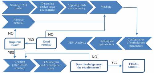
The methodology followed, from product design to manufacturing, comprises the main steps shown in the flow chart in .
Figure 2. Methodology flowchart.

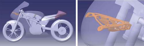
The first initial condition is the available design space. Within this space, it must be taken into account that the bracket must connect the steering pipe of the motorbike with the front fairing, offering support to the latter. In order to know the volume that can be used and occupied by the bracket, a “.CATProduct” file is used where the assembly of some of the motorbike components. shows in red the approximate proportion of the volume where it is possible to install the bracket.
Figure 3. Available design volume: a) Overview, b) Profile view.
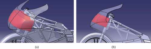
This volume has an estimated value of 0.011 m3 and its dimensions are conditioned by the positions of other elements of the motorbike. This is reflected above all in the height of the bracket, which must not interfere with the position of the dashboard, as this would make it impossible to install it. On the other hand, it is mandatory that the spider must cover the entire length of the defined field, since it does not otherwise fulfil the function of being the link between the steering and the fairing and of supporting the fairing. However, the delimitations in the width and depth of the design space do not exist, but are imposed by choice, especially for the aesthetics and structural coherence of the spider.
The second condition that the spider has to meet is to cope with the load state to which it is subjected during its service, which is composed of two main forces: the drag force, caused by the friction between the air and the vehicle when it is in motion, and the embedding in the steering pipe. It is this load state that is used during the optimisation process. The drag force used is calculated taking into account the entire front area of the fairing, but in reality this force is distributed over several areas of the bike, such as the fairing to chassis connections. To obtain the numerical value of this force it is necessary to turn to Aerodynamics, specifically to the equation (Anderson & Wendt, Citation1995):
Where FD is the drag force, Cx is the drag coefficient, A is the frontal area of the fairing, ρ is the density of the fluid, in this case air, and v is the speed at which the motorbike is moving. The numerical values of the different parameters used for the calculation of this force are shown in below, resulting in a value of FD = 136.13 N.
Table 1. Numerical data for the calculation of drag force
However, in order to further evaluate the strength of the spider, the behaviour of the spider under a higher drag force is studied. Specifically, two new values for the drag force are estimated: one keeping the data of 137 N but applying a safety factor of 1.25 (FD1.25) and the other considering that the motorbike travels at a maximum speed of 160 km/h (FDmax), giving as results 3 values of FD: 137, 173 y 243 N respectively.
The initial step in the methodology is the computer-aided design (CAD) of the spider from a simplified base geometry. Several base designs have been taken (), although this work will focus on the final choice, with a design in “trilateral” format as this is the one that best suits the needs. The CAD software used is CATIA, specifically version V5-V6 2020.
Figure 4. CAD base design of the spider a) main design b) other designs used.
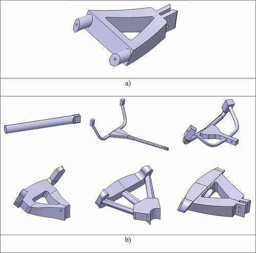
Each of the holes present in the model (6 in total) are the points where the bracket is screwed to make its adjustment. After the spider is manufactured, Helicoil thread inserts are installed to achieve a durable metallic thread.
Once the main structure and base of the spider has been generated using CATIA, the topological optimisation process is started following the steps shown in .
Figure 5. Flowchart of the topological optimisation process.
The forces to be worked with are the drag force indicated above and the support or embedment constraint on the pipe ()). The symmetry constraint was also applied. A triangular mesh with an initial cell size of approximately 3.24 mm is applied and optimised under the criterion of maximum stiffness. In this way, it is possible to create a structure with a customised mass distribution. The model is also divided into 3 main areas for a correct development of the design: the pipe grip area, the fairing attachment area and the body. The starting masses are shown in below. A minimum thickness of 12 mm is also indicated, with a view to correct and easy manufacture.
Figure 6. a) Force diagram; b) Test bench for experimental purpose.
Table 2. Initial mass of the model
Two different values for the weight of the fairing are considered in both the stop and the run: the total weight which is 19.6 N (WCT), as the fairing has a mass of 2 kg, and half of it, 9.8 N (WC/2). Several optimisations were carried out at Inspire, and different mass reduction percentages were established for each of the parts into which the spider was divided. To summarise, presents the different tests performed on the final topology with the described load states and the optimal mesh obtained from the convergence.
Table 3. Load cases for the final virtual prototype.)
Once the design is complete, the final model is produced by fused deposition modelling on the Creality CR-10 V3 printer with PLA. The final model is printed in the two main orientations, vertical and horizontal. The main parameters for the manufacture of this product are listed in . Once manufactured, post-processing is carried out to remove supports and improve the surface finish.
Table 4. Main manufacturing parameters used
Finally, an experimental test is carried out to validate the results, as it has been treated as a homogeneous solid, without taking into account the anisotropy of the additive manufacturing process. The test has been carried out on a load test bench that has been created specifically for this product ()), as the grip of the product allows for slight oscillation, as occurs on a motorbike. The spider must withstand a minimum load of 137 N, which translates to approximately 14 kg. The load applied to it will therefore increase from 4 to 68 kg.
3. Results
In order to achieve a small displacement, the force to be exerted on the workpiece should ideally be as parallel as possible to the orientation of the workpiece. For this reason, most designs have been established with small angles.
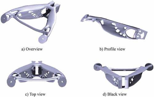
It should be noted that with respect to the initial design, the optimised spider experiences a decrease in mass of 80 %, and more if compared to the weight of the spiders currently available on the market. It should also be noted that the final volume is 146,170 mm3 and the dimensions are 237 × 210 x 89 mm, which fits perfectly in the design space ().
Figure 7. CAD model of the motorbike with the final spider assembled.
Therefore, in we show the part chosen after the topological optimisation process, in different views.
Figure 8. Final virtual prototype of the spider.
Once the final design has been chosen as a result of the topological optimisation, a FEM analysis will be carried out to check that the part meets the established load and displacement requirements. The numerical results obtained for the different parameters studied in the FEM analysis are shown in .
Table 5. Numerical values of the studied parameters
The initial requirements are that the displacement must be less than 1 mm and in this case the maximum value is 0.77 mm. In ) it can be seen in which areas of the spider the largest and smallest deformation occurs. As expected, the piece where the displacement is minimal, or even does not occur, is where the spider is embedded, while the highest deformation occurs in the area of the support where the fairing is directly supported. This deformation has the same direction and sense as the applied drag force.
Figure 9. (a) Displacement and (b) stress obtained in the loading study.
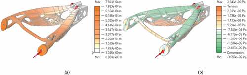
On the other hand, ) shows how the tensile and compressive stresses are distributed in the piece. The entire upper part of the spider is under the effects of compression, which is to be expected considering that this area is arranged approximately linearly to the direction in which the drag force is applied. Then, the bottom part, in response, is stressed, as is the front chord between the sides of the spider. It is important that neither of the two maximum values of tension and compression that are manifested exceed the yield strength of the material. The chosen material has a yield strength of 4.5107 Pa, so that there is no risk of fracture occurrence.
Also, almost completely the entire spider is subjected to a minimum Von Mises stress, 2.53103 Pa, and only a small area, where the connection between the body of the piece and the bolt holes occurs, is subjected to the maximum stress, 3.09106 Pa. However, this is of no concern because the yield strength of the material is an order of magnitude higher than this maximum value.
The study to which the spider was subjected in the previous section shows that it has suitable characteristics for the function it is to perform. However, this analysis was carried out with the size of the mesh element that the software automatically calculates, which is 0.0032447 m. There are occasions when, if a mesh is not fine enough, i.e. does not have a relatively small element size, information is lost. This is why new analyses are carried out where the size of the cells is modified in order to generate more and more precise meshes and to see how this influences the results. shows the values obtained for the parameters when the spider is studied by applying the initial load case, i.e. the drag force of 137 N and the embedding, depending on the mesh used.
Table 6. Results of the parameters obtained as a function of the mesh element size
When examining the results obtained with each of the five different meshes, the displacement stands out, as it is the same in all cases. It is the only parameter that remains unchanged. This is an indication that the automatic mesh is adequate for determining the deformation of the piece. On the other hand, the maximum safety factor increases with decreasing cell size, just as the minimum Von Mises stress decreases. However, the tension and compression, and therefore the maximum Von Mises stress, increase in value the finer the mesh size. However, at no time is the yield strength of the material exceeded. It should also be noted that, although the minimum limit of the safety factor decreases with the span of the element, a value of less than unity is never reached.
As indicated in the methodology (), 7 different analyses have been carried out. shows the results obtained for the different working conditions in each test. In each of the cases, different loading conditions will be studied, but in all cases an embedding constraint is applied.
Table 7. Results of the parameters obtained in the 7 analyses
Firstly, the values resulting from analyses 2 and 3 are commented on. Both differ from the initial one in that in analysis 2 the total weight of the fairing is applied and in analysis 3 half of it, which means that a state of load is being studied under real operating conditions. As can be seen, the stress and compression, as well as the Von Mises stress, in case 2 are lower, and the safety factor higher, than in case 3, which is somewhat unexpected as the weight is of a higher amount. Likewise, the value of the displacement in test 3 exceeds that of test 2. This is due to the fact that the drag force and the total weight force, when applied in different directions, compensate for the displacement in the area of the spider where it occurs, as well as the other parameters that are manifested. Secondly, case studies 4 and 5, where only the drag force is applied, as in the initial case, will be discussed. The variation is in the value of the forces. Analysis 5 has a much larger load than analysis 4, which is why all the parameters, except the safety factor, are of a higher value. The drag force applied in test 4 is 173 N and can be considered approximately as the limit load value valid in this work since, with a larger one, the displacement will likely exceed one millimetre. This is the case for case 5, where the force is 243 N and the displacement is 1.37 mm. This study also shows that even with a force of this calibre, the spider does not break. Finally, analyses 6 and 7 are presented, which correspond to the load case known as a standstill, so there is no drag force, only the weight of the fairing itself . On this occasion, as expected in test 6, higher values of the parameters are obtained, except for the safety factor, which is lower because the full weight is used, unlike what happens in test 7, where only half of it is used. Since the resulting numerical data are never outside the established ranges, it is concluded that the spider is capable of supporting the full weight of the fairing.
Once the final design was obtained, the prototype was manufactured for the experimental test (). It should be noted that, in addition to saving material and being environmentally friendly, the cost of the material used to obtain this product is 3.21 €, which gives very large profit margins compared to the parts currently on the market.
Figure 10. Final spider (a) printed, (b) post-processed.
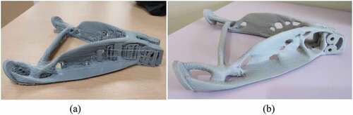
Finally, in the experimental test, a load of 68 kg was reached without showing any signs of breakage or deformation. The resistance to deformation offered by the spider is much higher than expected, as it is capable of resisting a load almost 5 times greater than that required. For this reason, it is understood that the material used could be further optimised.
With this result it is possible to state that the anisotropy of the piece when printed in the unfavourable direction is negligible. This again indicates that it is possible to remove even more material from the design.
4. Conclusions
A spider has been designed and manufactured that fully complies with the characteristics expected and imposed by a motorcycling competition team. This leads us to appreciate that opening the way to non-conventional technologies, such as additive manufacturing, provides numerous benefits. The most outstanding is the possibility of generating parts of great structural complexity, of any material, in a reduced time and at a low cost.
The manufacturing method is combined with the use of topological optimisation. As a result, it is possible to achieve parts that perform the same function as other pieces but with an improved and lighter structure that significantly reduces weight. In the automotive world, this is of vital importance since this reduction translates into a reduction in fuel consumption, which means an environmental improvement and better and more comfortable handling of the vehicle.
The structure of a fairing spider has been designed and manufactured by fused deposition modelling with PLA, and has been subjected to simulation and experimental tests to verify its commissioning. The tests demonstrated the validity of this structure at a lower cost than what is available on the market. In particular, if a comparison is made between the mass of the spider made in this work and those already on the market, it can be seen that a reduction of approximately 65–75 % is achieved. In addition, a biodegradable material is used as an alternative to welded metals.
Acknowledgements
The authors would like to thank to Sergio I. Molina and his group INNANOMAT (TEP946) for their helpful discussions and collaboration with the manufacturing of prototypes. Prototypes were manufactured at the Additive Manufacturing Division of SC-ICYT of the University of Cadiz.
Disclosure statement
No potential conflict of interest was reported by the author(s).
Additional information
Funding
References
- Anderson, J., & Wendt, J. (1995). Computational fluid dynamics. Vol. 206. New York: McGraw-Hill
- Bendsoe, M., & Kikuchi, N. (1988). Generating optimal topologies in structural design using a homogenization method. Computer Methods in Applied Mechanics and Engineering, 71(2), 197–14. https://doi.org/10.1016/0045-7825(88)90086-2
- Bendsoe, M., & Sigmund, O. (2003). Topology optimization: Theory, methods, and applications. Springer.
- Biancolini, M., Brutti, C., & Pezzuti, E., «Shape optimisation for structural design by means of finite elements method,» De XII ADM International Conference,12, Bologna, 2001.
- Cuong-Le, T., Minh, H.-L., Khatir, S., Abdel Wahab, M., Tran, M. T., & Mirjalili, S. (2021). A novel version of Cuckoo search algorithm for solving optimization problems». Expert Systems With Applications, 186, 115669. https://doi.org/10.1016/j.eswa.2021.115669
- Ehlers, T., & Lachmayer, R., «Design of a motorcycle triple clamp optimised for stiffness and damping,» De Proceedings of the Munich Symposium on Lightweight Design, Munich, 2020. (pp. 1-17). Springer Vieweg, Berlin, Heidelberg.
- Hodonou, C., Balazinski, M., Brochu, M., & Mascle, C. (2019). Material-design-process selection methodology for aircraft structural components: Application to additive vs subtractive manufacturing processes. The International Journal of Advanced Manufacturing Technology, 103(1–4), 1509–1547. https://doi.org/10.1007/s00170-019-03613-5
- Khatir, S., Abdel Wahab, M., Boutchicha, D., & Khatir, T. (2019). Structural health monitoring using modal strain energy damage indicator coupled with teaching-learning-based optimization algorithm and isogoemetric analysis». Journal of Sound and Vibration, 448, 230–246. https://doi.org/10.1016/j.jsv.2019.02.017
- Khatir, S., Tiachacht, S., Thanh, C. L., Ghandourah, E., Mirjalili, S., & Abdel Wahab, M. (2021). An improved artificial neural network using arithmetic optimization algorithm for damage assessment in FGM composite plates». Composite Structures, 273, 114287. https://doi.org/10.1016/j.compstruct.2021.114287
- Khatira, S., & Abdel Wahabb, M. (2019). « Fast simulations for solving fracture mechanics inverse problems using POD-RBF XIGA and Jaya algorithm ». Engineering Fracture Mechanics, 205, 285–300. https://doi.org/10.1016/j.engfracmech.2018.09.032
- Norato, J., Bendsøe, M., Haber, R., & Tortorelli, D. (2007). A topological derivative method for topology optimization. Structural and Multidisciplinary Optimization, 33(4–5), 375–386. https://doi.org/10.1007/s00158-007-0094-6
- Paris, J., Navarrina, F., Colominas, I., & Casteleiro, M. (2010). Improvements in the treatment of stress constraints in structural topology optimization problems. Journal of Computational and Applied Mathematics, 234(7), 2231–2238. https://doi.org/10.1016/j.cam.2009.08.080
- Primo, T., Calabrese, M., Del Prete, A., & Anglani, A. (2017). Additive manufacturing integration with topology optimization methodology for innovative product design. International Journal of Advanced Manufacturing Technology, 93(1–4), 467–479. https://doi.org/10.1007/s00170-017-0112-9
- Remache, A., Leguisamo, J., & Tamayo, E. (2019). Topological analysis using the finite element method of the chassis of a competition motorcycle. Automation and Control, Mechatronics, Electromechanics, Automotive, 10(3), 81–97. https://doi.org/10.29019/enfoque.v10n3.454
- Scappaticci, L., Bartolini, N., Guglielmino, E., & Risitano, G. (2017). Structural optimization of a motorcycle chassis by pattern search algorithm. Engineering Optimization, 49(8), 1373–1387. https://doi.org/10.1080/0305215X.2016.1256393
- Stejskal, T., Dovica, M., Svetlík, J., Demeč, P., Hrivniak, L., & Šašala, M. (2020). Establishing the optimal density of the michell truss members. Materials, 13(7), 3867. https://doi.org/10.3390/ma13173867
- Suryatama, D., & Bernitsas, M. (2000). Topology and performance redesign of complex structures by large admissible perturbations». Structural and Multidisciplinary Optimization, 20(2), 138–153. https://doi.org/10.1007/s001580050145
- Tran-Ngoc, H., Khatir, S., Ho-Khac, H., De Roeck, G., Bui-Tien, T., & Abdel Wahab, M. (2021). « Efficient artificial neural networks based on a hybrid metaheuristic optimization algorithm for damage detection in laminated composite structures». Composite Structures, 262, 113339. https://doi.org/10.1016/j.compstruct.2020.113339