
 ?Mathematical formulae have been encoded as MathML and are displayed in this HTML version using MathJax in order to improve their display. Uncheck the box to turn MathJax off. This feature requires Javascript. Click on a formula to zoom.
Abstract
The question of the thickness and diameter report on the performance of the structures is approached in detail in this scientific work. This paper focuses on the stress-strain characteristics, geometry imperfections, damage and deformations that occur inside the materials structure properties. Finite element analysis and experimental results show that, as loading progressed, the strain distribution in the shaft lining structure became approximately uniform indicating the formation of a tied arch mechanism. Concrete strain distribution is nonlinear and non-conform to Bernoulli’s assumptions for strain and stress distribution; this nonlinearity is due to the shear deformations inside the structural element. The study can provide certain reference for practical engineering calculation.
1. Introduction
There are large coal resources of various types in China where it plays a dominant role in energy consumption. Since the foundation of the new China, the coal industry has developed rapidly. The annual output of coal produced increased from 32.43 Mt in 1949 to 1 billion tonnes in 1989. Now China is able to design, construct and equip large-scale coal mines as well as coal-washing plants. The coal industry has reached a level as advanced as that in other countries. Since coal is the main energy source in China, rapid development of the industry will ensure that of the national economy (Huang et al., Citation2018; Wang, Citation2002; Xue et al., Citation2018).
With the recent development of coal resources in mid-eastern of China, engineers are facing some difficulties to penetrate the top soil with drilling shafts because of the greater soil thickness (the tertiary and quaternary system alluvium thickness is up to 600–800 m). This phenomenon can be observed in the coal field of Shandong, Anhui and West mine in Huaibei. Composite construction as we know it today was first used in both a building and a bridge in the U.S. over a century ago. The first forms of composite structures incorporated the use of steel and concrete for flexural members, and the issue of longitudinal slip between these elements was soon identified. Composite construction has been mainly applied to bridges and multistory buildings, with the more traditional forms of composite beams and composite columns (Benedicte, Citation2022; Huang et al., Citation2018; Yao et al., Citation2011).
The coal mining in China are developing very fast in the few decades towards the direction of the large scale and a deep water-bearing for weak rock formations. Wells are often constructed by freezing or drilling method due to the deep alluvium; also because of the geological exploration data in the western regions of Inner Mongolia, Shaanxi, Gansu, and some others places, it can be observed that the maximum mining depth has reached 1500 m. Actually we estimated the total proved coal resources are about 5.57 trillion tons and 47 mines with mining depth greater than 1000 m are repertoires in China and have been built in the few recent decade years (Benedicte, Citation2022; Yao et al., Citation2011).
E. Hoek and E. T. Brown (Hoek & Brown, Citation1980) in their research works have shown the relation between situ stresses and the depth of coal mines. For example, the vertical stress of a shaft wall lining structure will increase to 43.5 MPa for a depth of 1910 m. In this case, the consideration of the bearing capacity with a high value is necessary for a deep mining structures. Also, for some safety measures during the coal mining construction the bearing capacity of the structure can be optimize by the increasing of the concrete grade or strength. Another way is to raises up the thickness of the shaft lining structure; for shafts extending 1000 m depth, an increase of 10 mm (Benedicte, Citation2022; Hoek & Brown, Citation1980; Yao et al., Citation2011) is necessary to reinforced concrete high strength composite.
The rapid development of highways and underground constructions in China has recently led to major technological advances in research for underground support systems, as well as structural studies for tunnels. However, because of the specific geological conditions of certain areas, including rock mass deformations that occur accompanied by cracks, it appears essential to question the aspect of the impact of thickness for underground construction structures (Huang et al., Citation2018; Xue et al., Citation2018; Yao et al., Citation2011). Commonly, the high strength shaft lining structures is employed to resist strong outside loads; the composite steel lining and concrete means a cylindrical structure of inner and outer layers of steel plate tube with a filled high performance of concrete. Because of the non-negligible effect between steel and concrete, it appears primordial to know more about the structural parameters of the high strength composite, including the inner radius, the thickness, the Young’s modulus, the compressive strength of the concrete, include the bearing capacity of the shaft lining structure (Benedicte, Citation2022; Ghorbani et al., Citation2013; Hoek & Brown, Citation1980; Meschke et al., Citation1996; Naseri, Citation2020; Setoodeh et al., Citation2009; Yao et al., Citation2011).
The advanced high technology of metal hybrid materials has greatly influenced the vast field of materials engineering in the recent years (Wang, Citation2002; Xue et al., Citation2018). Of course, for specific application requirements, a necessity of materials with different properties is highly recommended; for example, advanced composite technology is adopted to ensure the composition and structure of materials with specific functions, properties, and thickness direction.
Notice that the structural material parameters have an impact on the stress-strain and displacement for a thick-walled cylinder under stress conditions. It appears crucial to understand the physical phenomenon that interact during the elastic working state of our studied structure (Ghorbani et al., Citation2013; Setoodeh et al., Citation2009). By using the elasticity theory, it will be evident to get close to the solutions of stress and displacement for a cylindrical structure under loads and pressure (Ghorbani et al., Citation2013; Meschke et al., Citation1996; Naseri, Citation2020). The elastic modulus changes nonlinearly along the radial direction of the material under uniform pressure. There is an effect of lining parameters on the stress and strain which need to be carefully analyzed.
The finite element software ABAQUS is employed for modeling, analyzing and simulation of a new high strength composite for coal mining application design. Finally, the plastic strain, compressive damage variable, tensile damage variable, compressive stress-strain curves, and load-displacement diagrams are obtained at the same time verified by incremental loading method employed on ABAQUS for solving the rationality of the shaft lining structures bearing in finite element dynamic analysis.
2. General methodology: Model geometry, boundary conditions, and loading
The nine studied shaft lining cylinders are investigated using the ABAQUS Finite Element Analysis package (Dassault Systems Simulia Corporation, Citation2010). For each parametric configuration, two models are solved; one with a frequency step and one with an Explicit Dynamic step to avoid convergence on calculations.
The model for double steel plate concrete shaft lining is illustrated in Figure .
Figure 1. Shaft lining structure model.
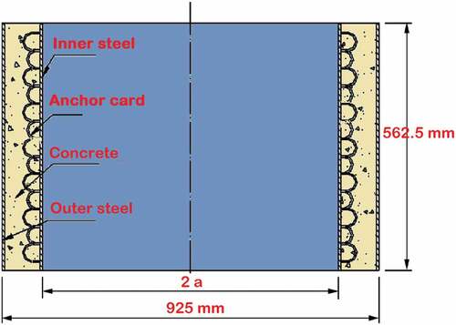
The steel anchor in the concrete is used to measure the stress, strain, and displacement of the studied structure. For an explicit dynamics analysis, the time is an important parameter for the real-time data collecting. There is the full-scale shaft lining dimensions, inner and outer thickness, also specimen’s concrete strength grade. The height and width of the anchor are half the thickness of the shaft lining model.
Numerical simulations of shaft linings composites were done by using commercial software ABAQUS Standard 6.12 (Dassault Systems Simulia Corporation, Citation2010). The concrete material was modelled as a homogeneous 3D solid section; the Drucker–Prager plasticity model is used during the numerical simulation of the composite. The numerical model should be able to capture the critical and essential phenomena that occurs inside the material structure (Chen et al., Citation2013; Cusatis, Citation2011; Do et al., Citation2018; Georgin & Reynouard, Citation2003; Guo et al., Citation2017; Hao & Hao, Citation2011; Jin et al., Citation2020; M. Li et al., Citation2018; Park et al., Citation2001; Ye et al., Citation2019; Zhou et al., Citation2016).
The axial and tangential axes are constrained along the circumference. The cylinder bottom is encastred with pinned conditions, while the top cylinder is subject to peak deformations. All the steel cylinders of the composite are fixed at the bottom, and the top end is kept free in all directions with the applied axial loading. Embedded region constraint available in ABAQUS Standard is used to define the bonding of steel-concrete composite. To determine the axial load-deflection history of shaft lining structures up to failure, a static monotonic load is applied at the top by the displacement control. The constraint tie is used to apply the boundary conditions and an equal distribution of different loads. The steel plates are considered as rigid elements with Young’s modulus of 210 GPa and density of 7.85.10−9 ton/mm3. The most specific details of the geometry and modelling finite element models of shaft lining composites are shown in Figure .
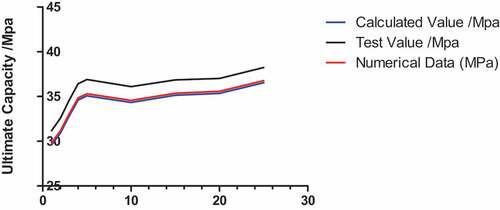
Figure 2. Comparison curves of ultimate bearing capacity of shaft lining structures.
The nine studied models are composed of two materials: steel and concrete. When the concrete is undergoing elastic deformations, the circumferential stresses are distributed according to the stress distribution law of thick-wall cylinders defined by:
Where is stress circumference of the concrete; the external load;
is the inner radius and b the outer radius of the shaft lining structure; r is the radius at the calculation point in the finite element software.
For the comprehensive physical and mechanical properties of the nine studied shaft lining composites, we can refer to the Table . The modulus of elasticity (Ec) of concrete was calculated using the American Concrete Institute code given by the following expression:
Table 1. Physico-mechanical parameters of shaft lining structures
The master and slave surface concept was used to define the interaction between concrete cylinders and steel plates. The bottom surface of the top steel plate and the bottom surface of the concrete cylinder was taken as master’s surfaces; the top surface of the concrete cylinder and the top surface of the bottom steel plate are considered as slave’s surfaces. The load transferring surfaces are taken as master surfaces.
A total of 09 full-scale cylinders specimens were modelled in ABAQUS under different loading conditions, from which all the 09 specimens were reinforced longitudinally and transversely with thin steel cylinders (the thin steel cylinders have different diameter ratio according to their inner and outer diameter thickness).
The yield stress surface makes use of two invariants, defined as the equivalent pressure stress,
And the Mises equivalent stress,
Where S is the stress deviator, defined as:
In addition, the linear model also use the third invariant of deviatory stress,
Alternatively, the strain rate behavior can be assumed to be separable, so the stress-strain dependence is similar at all strain rates:
Where is the static stress-strain behavior and
is the ratio of the yield stress at nonzero strain rate to the static yield stress. Two methods are offered to define R in ABAQUS; specifying an overstress power law or defining the variable R directly as a tabular function of
The Cowper-Symonds overstress power law has the form:
Where and
are material parameters that can be functions of temperature and, possibly, of other predefined field variables.
At the ultimate load state, the compressive strain distribution in the concrete is nonlinear as it no longer follows the parabolic shape or intensity linearity of normal (shallow) shaft linings. This condition is due to the predominant effect of the post-cracking, the reduction in the concrete’s compression area and the shear deformation that is prevalent in shaft linings structures.
In ABAQUS/Explicit, the extended Drucker–Prager models can be used in conjunction with the models of progressive damage and failure.
2.1. Characteristics of the Drucker–Prager model
According to the size of the loading device for the simulation test of high-strength shaft lining structure in the Institute of underground engineering structure of Anhui University Science Technology, the outer diameter and height of the model specimen are 925 mm and 562 mm, respectively. Through calculation, the geometric similarity ratio of the shaft wall model of the north air shaft of taohutu coal mine is 8.7567, the design shaft wall model parameters are shown in Table , and the thickness diameter ratio is 0.2466. The wellbore model structure is shown in Figure , and the test results can verify the numerical simulation values.
Figure 3. Wellbore model structure.
Table 2. Parameters and capacities of shaft lining models
Generally, the cracks propagated toward the loading point as the load is increasing; we can observe more flexural-shear cracks along the shaft lining shear spans, as shown in Figure .
Figure 4. Shape and propagation of cracks during loading till failure of the shaft lining structure.
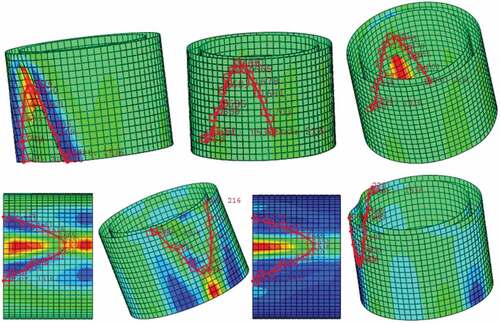
The strain distribution along the bottom layer of the borehole cylinder as the load increased is shown in Figure ; as more cracks formed closer to the supports, the measured strains in the composite model would also increase closer to the support. Wellbore structure model parameters and Damage parameters are provided in .
Table 3. Wellbore structure model parameters
According to the Concrete Damage Plasticity model, the following non-associated potential plastic flow rule is used:
Where and
denote the stress and plastic strain rate tensors, respectively,
is a plastic multiplier and G defines Drucker–Prager hyperbolic function in the model given by the below equations.
Where and
are the hydrostatic stress and the von-Mises equivalent stress, respectively. The parameter
is the dilation angle registered in the
plane at high confining pressure.
Denotes the eccentricity of the potential plastic surface, which is defined as the rate at which the function reaches the uniaxial tensile.
Table 4. Damage parameters data before failure
The stress–strain relationship of the concrete has a linear relationship, and the stress–strain relationship is expressed as follows:
This linear relationship can be determined based on the secant modulus of concrete materials, which is determined by the following equations:
When the concrete reaches the crushing strain, and the stress–strain relationship is nonlinear and determined by the following equation:
Where is the Modulus of concrete’s elasticity
The concrete stiffness starts to decrease due to the appearance of , and the stress–strain relationship can be calculated by using the below equation.
Where ,
are the stress and strain at the complete crushing. For this research paper, we consider
and the parameter
also
are not obtained from experimental data; their values are proposed to match the numerical data and experiments. We should remember that the values of
and
are only useful for the high concrete grades as C65, C70, C75. The stress–strain relationship of the nine studied shaft lining models are presented in the Figures
The Figures show the relationship of compressive damage variable-crushing strain of shaft lining models C65, C70, and C75.
Figure 5. Compressive damage variable (dc) vs. crushing strain.
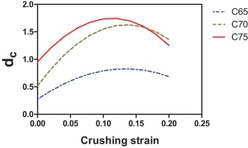
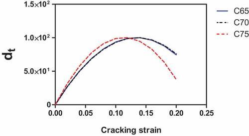
Figure 6. Tensile damage variable (dt) vs. Cracking strain.
The stress-strain relationship is considered linear and determined through the modulus of elasticity. The mesh size in the Finite Element Method is responsible of the convergence after the model implementation.
The curve of stress-crack opening to replace the stress-strain curve is given by the below equation.
Where ;
and
is the critical crack opening; it can be considered as the fracture crack opening according to the following equation.
For the numerical analysis of this paper, the crack spacing is ignored because of the mesh size effects. Also, we can observe that the crack occurs in each element after tensile stress reaches a maximum peak. The strain at tensile strength can be calculated from crack opening by the below equation.
Where is the length of the element mesh or the mesh size. From the obtains results, we deduct that the tensile stress-strain is more suitable when we use the finite element analysis.
3. Numerical simulation results of high-strength composite shaft linings
The experiments of Reference work (Benedicte, Citation2022; Yao et al., Citation2011) are used to quantify the average compressive strength in the static and dynamic conditions of concrete composites Z1 to Z9. The specific concrete grades are C65, C70, and C75 with a model structure height varying between 98.1 mm and 108.8 mm.
Plots of the strain-stress variations determined by the Finite Element analysis along the section circumference of the cylinder under first crack load and ultimate load are shown in Figures . It shows that the strain-stress distribution in the shaft lining structure is nonlinear. The compression strain in the top circumference cylinder increases as the load increases; but in the tension area, the strain predictions are disturbed by the cracks propagation.
Figure 7. Strain and loading correlation curves between the inner and outer of steel plates for the different shaft lining models.
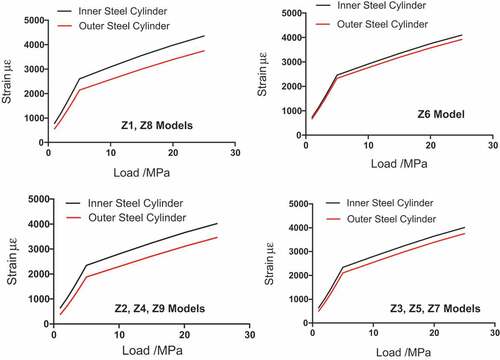
Figure 8. Correlation curves between strain and load of the shaft lining steel-concrete structure, inner and outer edge for the different models.
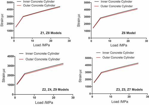
Figure 9. Stress and loading correlation curves between the inner and outer of steel plates for the different shaft lining models.
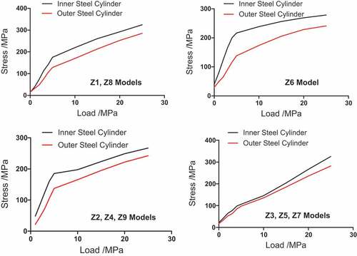
Figure 10. Correlation curves between stress and load of the shaft lining steel-concrete structure, inner and outer ledge for the different models.
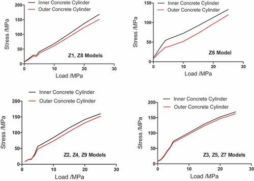
Figure 11. Compressive stress-strain curves of typical concrete C70 under different strain rates.
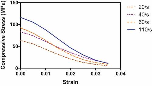
Under the dynamic conditions with the application of the static load, the stress-strain curves show an increase in the compressive strength of the concrete.
We noticed that the load hoop stress of the steel and concrete are constrained. The whole structure is subject to compressive stress under uniform load. We observed a high deviation of the stresses values when the concrete structure entered the elastic-plastic stage.
The critical value is obtained at the failure load step, which satisfied the stress and deformation conditions. The linear load is observed at the elastic stage of the concrete; the load increase has a direct impact on the strain and plastic stage of the concrete. We can conclude that the shaft lining diameter-ratio considerably affect the bearing capacity of the nine studied composite cylinders.
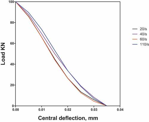
The Figure shows that the shaft lining composite is far from being linearly elastic when the ultimate load is reached. This nonlinearity of strain distribution is due to the shear deformations that are often less obvious in concrete structures, but that are significant in shaft lining steel-concrete composites.
The compressive strains along the shaft lining structure with the highest measured strain are around 0.04. This behavior is attributed to the low elastic modulus of the steel-plates cylinders. We can observe a reduced effective moment of inertia and some large deflections (see, Figure ).
Figure 12. Effect of steel-plates on load-deflection response of shaft linings composite structures.
This paper predicts the compressive damage effects and stress-strain response of nine shaft lining composites using a Finite Element Software ABAQUS. The obtained results show an ad-equation between experimental and numerical data. The concrete damaged plasticity model is used for the modelling of nonlinearity of the composite structure. The finite element modelling is the most challenging part of the research paper, especially the numerical modelling of concrete in shaft lining composite structures. The Concrete Damaged Plasticity model in this paper is also available in the ABAQUS finite element software but have been modified to improve the compressive stress-strain curve of the studied models. Also, the damaged variables are beneficial for the new version of high-strength concrete C65, C70, and C75 under static loading. Numerical calculation is an effective method to study the bearing capacity of shaft lining structures. The nine studied shaft lining models reach ultimate destructive state according to the development of the stress, strain, and displacement of the Finite Element Method numerical results. It is crucial to notice that the plastic displacement and the structure deformation notably influence the bearing capacity of shaft linings structures.
The bearing capacity vary at the ultimate elastic load until the failure of the shaft lining composite, and a linear relationship is observed between the hoop strain of the steel and the concrete when the applied load increase with time. The steel strain value is much higher than for the concrete.
Before the structure failure, specific results for strain are obtained: ultimate load capacities equal to 40 MPa; the limit loop strain of steel and concrete varying between 4000 and 6000 ; the limit loop stress of steel is about 300–400 MPa, while for the concrete is about 150–200 MPa.
For the damaged structure, the maximum hoop stress of the shaft lining reaches the value of 300 MPa, which exceed the numerical compressive strength of the concrete. During the loading process, the concrete of the inner and outer of shaft lining model switch from the bidirectional to the three-dimensional compression state. Notice that the shaft lining structure did not buckle at the plastic deformation stage; especially the inner steel cylinder of the composite.
The experimental data of the reference (Benedicte, Citation2022; Yao et al., Citation2011) verified the numerical data of the compressive strength for this research paper; the concrete hoop stress for all the nine specimens will increase higher and higher until the failure of the structure.
The concrete grade C70 shows optimum numerical results with a high bearing capacity compared to the two other concrete grades C65 and C75. We can conclude that the thickness diameter ratio has an impact on the structural properties of the shaft lining steel-concrete. For the specimens with a high thickness diameter ratio as for Z3, Z5, and Z7, we observe good results compared to other specimens: the inner and outer thickness of the steel and concrete are the induct parameters of the shaft lining performances properties.
4. Conclusion
Predictions of simulation, it emerges an acquisition with the first experienced results. This scientific research has reached compressive behavior and stress-strain response of the different Z1, Z2, Z3, Z4, Z5, Z6, Z7, Z8, and Z9 specimens.
The limits of this study concern much more in determination of failure and strain-stress deformations of constitutive models used for shaft linings concrete by ABAQUS are able to capture.
The main applicability of Steel-Concrete Composite is in the form of corrugated structures such as aircraft wing webs, decking, wall sheeting, and roofing members of buildings. Laminated composite shell structures are finding widespread applications in aerospace and marine industries. Their main advantages reside on their high strength to weight ratio, high stiffness to weight ratio, long fatigue life and environmental stability due to the absorption capability, and low maintenance cost.
Availability of data and materials
All numerical setting data are presented in the article.
Acknowledgment
We are grateful to Professor Yao Zhishu from School of Civil Engineering and Architecture, Anhui University of Science and Technology, for providing the experimental data needed for numerical calculations in this research paper. For the guidance and methodology of this article, we want to express our gratitude to Professor Yao Zhishu, Professor Bin Tang, Professor Xianwen Huang for all the scientific knowledge they provided to us during the classes and for the academic tutoring for the Doctoral Thesis Research.
Disclosure statement
No potential conflict of interest was reported by the author(s).
Additional information
Funding
Notes on contributors

Bénédicte Touogam Touolak
Bénédicte Touogam Touolak PhD Computer Methods in Applied Mechanics and Engineering, Senior Researcher at Anhui University of Science and Technology [email protected]
Institution and department
Anhui University of Science and Technology
Department of Civil Engineering
References
- Alfarah, B., Lopez-Almansa, F., & Oller, S. (2017). New methodology for calculating damage variables evolution in Plastic Damage Model for R.C. structures. Engineering Structures, 132, 70–17. https://doi.org/10.1016/j.engstruct.2016.11.022
- Benedicte, T. (2022). Numerical analysis of the structure of high-strength double-layer steel plate concrete shaft by drilling method of Water-bearing weak rock formation. Open Journal of Civil Engineering, 12(2), 189–207. https://doi.org/10.4236/ojce.2022.122012
- Chen, X., Wu, S., & Zhou, J. (2013). Experimental and modeling study of dynamic mechanical properties of cement paste, mortar and concrete. Construction and Building Materials, 47, 419–430. https://doi.org/10.1016/j.conbuildmat.2013.05.063
- Couture, A., François, V., Cuillière, J. C., & Pilvin, P. (2020). Statistical volume element modeling based on the unified topology model “. International Journal of Solids and Structures, 191-192, 26–41. https://doi.org/10.1016/j.ijsolstr.2019.11.007)
- Cusatis, G. (2011). Strain-rate effects on concrete behavior. International Journal of Impact EngEngineering, 38(4), 162–170. https://doi.org/10.1016/j.ijimpeng.2010.10.030
- Dassault Systems Simulia Corporation. (2010). ABAQUS Analysis User’s Manual 6.10-EF.
- Do, T. V., Pham, T. M., & Hao, H. (2018). Dynamic responses and failure modes of bridge columns under vehicle collision, Eng. Struct, 156, 243–259.
- Ferraioli, M. (2019). Dynamic increase factor for nonlinear static analysis of rc frame buildings against progressive collapse. International Journal of Civil Engineering, 17(3), 281–303. https://doi.org/10.1007/s40999-017-0253-0
- Georgin, J., & Reynouard, J. (2003). Modeling of structures subjected to impact: Concrete behavior under high strain rate, Cement Concr. Compos, 25(1), 131–143.
- Ghorbani, A., Hasanzadehshooiili, H., Apalas, A., & Lakirouhani, A. (2013). Buckling of the steel liners of underground road structures: The sensitivity analysis of geometrical parameters. The Baltic Journal of Road and Bridge Engineering, 8(4), 250–254. https://doi.org/10.3846/bjrbe.2013.32
- Guo, Y., Gao, G. F., Jing, L., & Shim, V. P. W. (2017). Response of high-strength concrete to dynamic compressive loading. International Journal of Impact Engineering, 108, 114–135. https://doi.org/10.1016/j.ijimpeng.2017.04.015
- Hao, Y., & Hao, H. (2011). Numerical evaluation of the influence of aggregates on concrete compressive strength at high strain rate. International Journal of Protective Structures, 2(2), 177–206. https://doi.org/10.1260/2041-4196.2.2.177
- Hao, Y., & Hao, H. (2014). Influence of the concrete DIF model on the numerical predictions of R.C. wall responses to blast loadings, Eng. Struct, 73, 24–38.
- Hoek, E., & Brown, E. T. (1980). Underground excavations in rock. Institution of Mining and Metallurgy.
- Huang, W. P., Yuan, Q., Tan, Y. L., Wang, J., Liu, G. L., Qu, G. L., & Li, C. (2018). An innovative support technology employing a concrete-filled steel tubular structure for a 1000-m-deep roadway in a high in situ stress field, Tunn. Tunnelling and Underground Space Technology, 73, 26–36. https://doi.org/10.1016/j.tust.2017.11.007
- Jin, L., Yu, W., & Du, X. (2020). Effect of initial static load and dynamic load on concrete dynamic compressive failure. Journal of Materials in Civil Engineering, 32(12), 04020351. https://doi.org/10.1061/(ASCE)MT.1943-5533.0003439
- Li, M., Hao, H., Shi, Y., Hao, Y. (2018). Specimen shape and size effects on the concrete compressive strength under static and dynamic tests. Construction and Building Materials, 161, 84–93. https://doi.org/10.1016/j.conbuildmat.2017.11.069
- Li, S. C., Lu, W., Wang, Q., Sun, H. B., Jiang, B., Qin, Q. (2018). Study on failure mechanism and mechanical properties of casing joints of square steel confined concrete arch. Engineering Failure Analysis, 92, 539–552. https://doi.org/10.1016/j.engfailanal.2018.05.011
- Meschke, G., Kropik, C., & Mang, H. (1996). Numerical analysis of tunnel linings by means of a viscoplastic material model for shotcrete. International Journal for Numerical Methods in Engineering, 39(18), 3145–3162. https://doi.org/10.1002/(SICI)1097-0207(19960930)39:18<3145::AID-NME992>3.0.CO;2-M
- Nana, A., Cuillière, J. C., & François, V. (2017). Automatic reconstruction of beam structures from 3D topology optimization results “. Computers and Structures, 189, 62–82. https://doi.org/10.1016/j.compstruc.2017.04.018)
- Naseri, S. (2020) Design of initial shotcrete lining for a mine shaft using two-dimensional finite and hybrid finite-discrete element methods. MASc thesis, Dalhousie University
- Park, S., Xia, Q., & Zhou, M. (2001). Dynamic behavior of concrete at high strain rates and pressures: II. numerical simulation. International Journal of Impact Engineering, 25(9), 887–910. https://doi.org/10.1016/S0734-743X(01)00021-5
- Setoodeh, S., Abdalla, M. M., Ijsselmuiden, S. T., & Gürdal, Z. (2009). Design of variable stiffness composite panels for maximum buckling load, Compos. Struct, 87, 109–117.
- Touogam Touolak B, Yao Z, Tang B and Huang X. Prediction of Nine Quasi-Isotropic Thin Steel Cylindrical Shells Axial Buckling Capacity Under Bending (Plasticity) and Axial Compression (Linear Elasticity). SSRN Journal, 10.2139/ssrn.4064549 2023
- Wang, Y. C. (2002). Steel and composite structures – analysis and design for fire safety. Spon.
- Xue, Y., Zhang, X., Li, S. et al. (2018). Analysis of factors influencing tunnel deformation in loess deposits by data mining: A deformation prediction model, Eng. Geol, 232, 94–103.
- Yao, Z., Song, H., & Cheng, H. (2011). Test study on mechanical characteristic of high strength composite shaft lining of steel and concrete. Key Engineering Materials, 480-481, 568–573. https://doi.org/10.4028/www.scientific.net/KEM.480-481.568
- Ye, Z., Hao, Y., & Hao, H. (2019). Numerical study of the compressive behavior of concrete material at high strain rate with active confinement. Advances in Structural Engineering, 22(10), 2359–2372. https://doi.org/10.1177/1369433219841174
- Zhou, W., Tang, L., Liu, X., Ma, G., Chen, M. et al. (2016). Mesoscopic simulation of the dynamic tensile behavior of concrete based on a rate-dependent cohesive model. International Journal of Impact Engineering, 95, 165–175. https://doi.org/10.1016/j.ijimpeng.2016.05.003