
 ?Mathematical formulae have been encoded as MathML and are displayed in this HTML version using MathJax in order to improve their display. Uncheck the box to turn MathJax off. This feature requires Javascript. Click on a formula to zoom.
Abstract
The power take-off (PTO) torque measuring system was designed, which includes a torque transducer and a digital wireless system to receive, process, and display the observed PTO torque. A dynamic PTO torque transducer was developed using strain gauges to fit in between the PTO shaft of the tractor and the universal shaft of the implement and simulated using SolidWorks software with 1000 Nm twisting moment along with 100 N load. To transmit torque signals from the revolving PTO shaft, an embedded system was developed. The embedded system was tested in the laboratory and under actual field conditions. The digital wireless embedded system comprised an amplifier cum analog to digital converter to amplify the received signal from the torque transducer and convert it into a digital value. A microcontroller processes the digital value given by the amplifier, and radio frequency (RF) receiver module was mounted on the Xbee explorer to receive the transmitted data from the RF module of signal processing and transmitter unit. The developed system was tested under field conditions, and data were compared with the existing commercial torque transducer. The results showed that the relative deviation between the observed mean PTO torque values obtained from the developed torque transducer and that from the existing torque transducer was 8.57% and 9.06% at 2.5 km/h and 3.5 km/h, respectively.
1. Introduction
Tillage is one of the most energy-intensive operations in an agricultural production system. The tractor is used as a power source in an agricultural operation. There are three ways to utilize the power of a tractor for agricultural operation, i.e. drawbar power, hydraulic power, and power take-off (PTO) (Taylor et al., Citation1991). PTO is one of the most important power sources to give rotational motion to active-type implements (Sarkar et al., Citation2021). About 90% of net flywheel power is available at PTO power (ASABE, Citation2011). To achieve maximum utilization of the tractor’s power output, the tractor implements should be properly matched. The measurement of PTO torque has received considerable attention in tractive performance studies. Matching of tractor implements helps to decide the depth, width of implements, and size of the tractor (Grevis-James, Citation1979). Sahu and Raheman (Citation2008) developed a decision support system for matching tillage implements with two-wheel drive tractors and for predicting the field performance of the tractor-implement system. In the past, many instrumentation systems have been developed to measure a tractor’s PTO torque while operating an active implement such as rotovator in the field is desirable, but the majority of the systems were designed for a specific tractor. Ghosh (Citation1967) developed a slip ring-based torque sensor to measure torque of rotavator shaft using strain gauge. The unbalanced signal was generated by the strain gauge while transferring to the data recorder. A brushless torque meter was designed (Mahmoud et al., Citation1972) to measure the torque at 540 rpm using a strain gauge. The sensitivity of the torque meter depends on the shape of the conical-shaped seat to produce the tension. Vigneault et al. (Citation1989) who developed a torque meter was mounted on the trailer which provides hitched system to the implement. However, it was revealed a possibility of overturning. Furthermore, an angular twist-type torque transducer torque meter using two encoders was designed and developed (Cheong et al., Citation1999) to measure the torque of the rotating shaft. However, it limits the variation between measured axial strain and calculated axial strain. Lee et al. (Citation2015) developed load measurement system with strain gauge sensors to measure the torque of the PTO driving shaft. It showed that average torque was increased with increasing rotational speed of the PTO. Choi et al. (Citation2021) investigated the dynamic behaviour of PTO driveline using simulation. However, it confirmed that collision was responsible for the change in the dynamic behaviour. Celik et al. (Citation2018) examined the deformation simulation using finite element method for tractor’s PTO shaft. The loading test method of the tractor PTO load spectrum is explored. The outcomes of the real tests demonstrate that the loading system’s output torque responds well (Wang et al., Citation2021). The strength analysis of a PTO gear-train of a multi-purpose cultivator was performed using actual measured loads during rotary ditching operation. However, it showed that arrangement of gear stages has a significant impact on strength of the PTO gear-train (Kim et al., Citation2019). Roeber et al. (Citation2017) calibrated a torque sensor using dynamometer at different loads. The calibration value was verified with the Organisation for Economic Co-operation and Development (OECD) code. Kim et al. (Citation2016) measured the PTO torque of transplanter during the field condition. The torque measurement system was developed using strain gauge sensors, but it revealed that fluctuation of PTO shaft was depended on the depth and planting distance. Various wire-based data acquisition systems are available to measure a tractor’s PTO torque, which is very complicated to use and create problems during the operation. Hence, there is a need to design and develop PTO torque transducer integrated with an embedded digital wireless system for signal processing and logging unit for PTO torque transducer data.
2. Materials and methods
Measurement of PTO shaft torque plays a crucial role in the collection of power requirement data for various PTO-driven implements. Hence, there is a need for a precision PTO shaft torque transducer, which is suitable for commonly used agricultural tractors and is required to collect the PTO torque information on the various tractor and PTO-driven implement combinations.
2.1. Design considerations
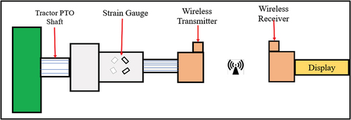
A transducer must be connected between the PTO shaft and the implement shaft. The signals from the signal processing cum transmit unit of the developed PTO torque transducer were transmitted the data to the receiver unit for displaying PTO torque.
2.2. Concept of torque measurement of developed PTO torque transducer
A torque transducer sensor to fit on the tractor PTO shaft was designed and developed to measure the PTO shaft torque in dynamic conditions. The developed transducer contains an extension shaft, which was made in three sections. One end of the transducer has six internal splines to allow it to fit in the tractor’s PTO shaft, and the other end of the transducer was made outer splined having six splines on to attach any PTO-driven implements with the tractor. Rosette-type strain gauges were mounted in the middle section of the developed shaft to measure PTO torque. It is impossible to take the signal by wired communication due to the continuous rotary motion of the PTO shaft. Hence, a wireless embedded system based on a microcontroller was developed to read, process, and display the strain gauge signal. The conceptual diagram of the developed PTO torque measurement is shown in .
Figure 1. Conceptual layout of PTO torque measurement.
2.3. Dynamic simulation of PTO shaft
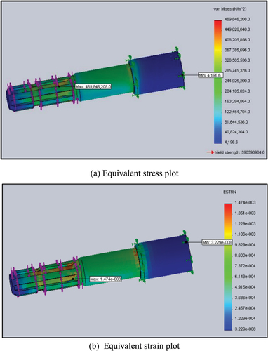
To determine the maximum load-bearing capacity of the developed extension shaft, a dynamic simulation in SolidWorks (SW2018) software (Dassault Systemes SolidWorks Corporation, USA) was performed with a twisting moment of 1000 Nm and a load of 100 N. The minimum and maximum stress development were found to be 4.19 × 10³ Pa and 489.84 × 10³ Pa, respectively (Figure ). The same procedure was repeated using the twisting moment for dynamic simulation, and the maximum and minimum strains were found to be 1.47 × 10⁻³ and 3.22 × 10⁻⁸, respectively (Figure ). Uniform stress distribution was observed along the length of the extension shaft. Therefore, a shaft was developed, and strain gauges were installed at 45° to the shear plane in the shaft’s middle section (Hensh et al., Citation2021b; Kheiralla et al., Citation2004; Kumar et al., Citation2017; Upadhyay et al., Citation2022).
Figure 2. Dynamic simulation of developed torque transducer (a) & (b).
2.4. Development of torque transducer
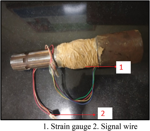
To measure the torque of the PTO shaft with six splines at 540 rpm on all agricultural tractors, a universal torque transducer was designed and developed. The rosette strain gauges were used to measure the torsional strain induced in the shaft under loading conditions. The strain gauge (SGT-2/350-XY11, Omega Engineering, India) has a resistance of 350 ohm and a gauge factor of 2.1. The strain gauge installation was carried out after smoothing the middle section of the extension shaft surface with fine silicon carbide abrasive paper. The four-rosette strain gauge was bonded on the middle section of the extended shaft at a 45° shaft axis and connected to the full Wheatstone bridge configuration. The installed strain gauges were permanently glued with epoxy adhesive. Finally, a protective coating was applied to the gauges that were installed to protect them from water, humidity, and mechanical abrasion. Two of its ends were used to supply power to the circuit, and the remaining two were used to take the output from the bridge. The developed PTO torque transducer is shown in Figure .
Figure 3. Developed PTO shaft torque transducer.
3. Validation of the developed transducer in the laboratory
3.1. Calibration setup for PTO torque transducer
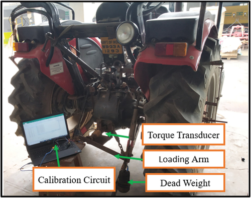
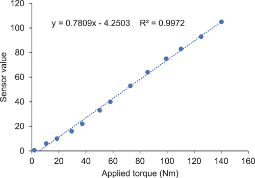
The torque transducer was calibrated to determine how sensitivity and linearity varied at different dead loads. During calibration, one end of the developed shaft was attached to the tractor’s PTO shaft, and the other end of the shaft was fitted with a loading arm to apply dead weight to it. The applied load was transferred to the transducer through a 40 cm length of loading shaft. The output of the transducer is fed to the analog pin of the HX711 analog to digital converter (ADC) (Evelta Electronics, India) cum amplifier to convert the digital signal with amplification. Change in digital value (sensor value) with applied torque was recorded on the computer, and graphs were plotted between applied torque and sensor value. It was observed a very linear relationship between the sensor value and applied torque. The calibration setup is shown in Figure .
Figure 4. Calibration setup for developed PTO torque transducer.
3.2. Development of calibration circuit
The calibration circuit (Figure ) comprised a microcontroller and HX711 (ADC cum amplifier). HX711 was connected to the PTO torque transducer and microcontroller. HX711 received a signal from the PTO torque transducer and amplified it when the dead load is applied to the loading arm. After amplification of the output signal of the torque transducer, the amplified signal is sent to the microcontroller (ATMEGA328, Smart Projects, India). The calibration curve is shown in Figure .
Figure 5. The calibration circuit of the developed PTO torque transducer.
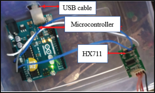
Figure 6. The calibration curve for the developed PTO torque transducer.
3.3. Development of the wireless embedded system
3.3.1. Amplification
During laboratory calibration of developed PTO torque transducer, output signals of torque transducer were low values; hence, to avoid error in signal processing cum transmitting unit, there is a need of amplifier cum ADC to amplify and convert it into digital signals.
3.3.2. Configuration of Xbee module
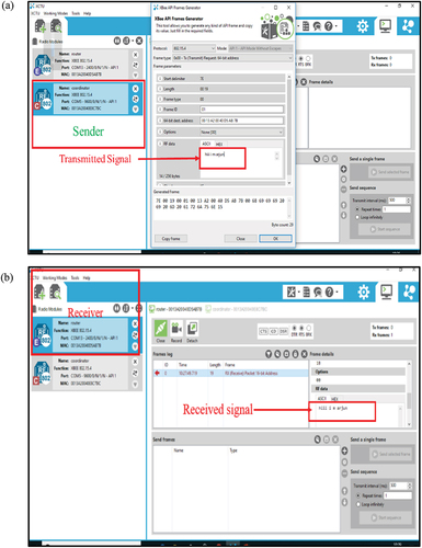
To receive the transmitted signals of the transmitter, both the Xbee modules (Digi International, India) of the transmitter and receiver unit need to be properly configured (Kumbhar, Citation2016; Orgon et al., Citation2019; Sahitya et al., Citation2017; Tuan, Citation2019). To configure the Xbee modules, XCTU terminal software was used. The channel and Pan ID for both the Xbee were kept the same. The source address of the transmitter was made the destination low address of the receiver, and the destination low address of the transmitter was made the source address of the receiver. The transmitter was written as a coordinator, and the receiver was enabled as the router. Other settings and configurations were also written as per the requirement. XCTU configuration window is shown in Figures .
Figure 7. XCTU configuring window for transmitter (a) and receiver Xbee module (b).
3.3.3. Development of signal processing cum transmitting unit
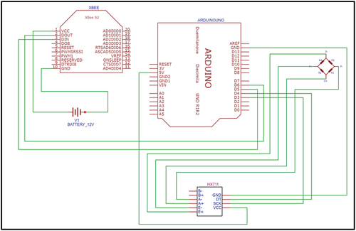
Because of the rotary motion of the tractor PTO shaft, it is extremely difficult to track and record the signals from the strain gauges mounted on the torque transducer. Therefore, to read, process, and transmit strain gauge data, a signal processing cum transmitter unit was developed. It included an ADC cum amplifier, a microcontroller, an Xbee shield, and radio frequency (RF) transmitter modules. The strain gauge wires were connected to the pin of HX711 to convert the analog output signal into a digital signal and amplify the digital value to avoid the error. The amplified strain gauge signal is sent to the microcontroller (Arduino) to process. To pick up the processed signal, an Xbee shield was connected to the microcontroller. An RF module was installed over the Xbee shield of the transmitter unit to receive the processed signal and sent it to the receiver unit. The developed signal processing cum transmitter unit is shown in Figure .
Figure 8. Circuit diagram of signal processing cum transmitting unit.
3.3.4. Development of receiver and display unit
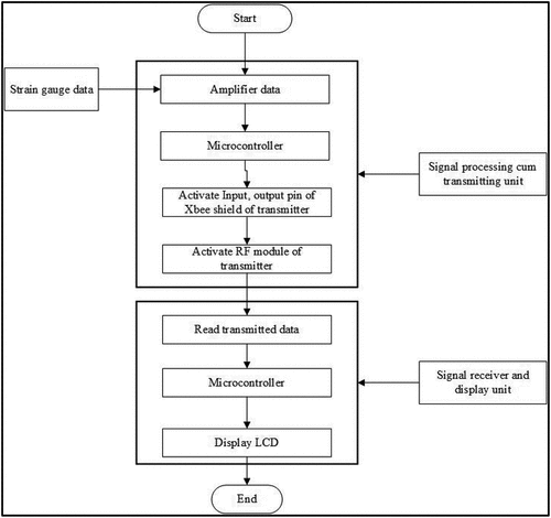
A receiver unit was developed to receive and display the transmitted signals from the transmitter unit. It included an RF receiver module that received data from the transmitter unit, and Xbee shield was used to read the RF module data, which was connected to the pin of the microcontroller to store and digitally display on the LCD screen. The developed receiver cum display unit is shown in Figure , and the flowchart of the developed PTO torque transducer is shown in Figure .
Figure 9. Circuit diagram of receiver cum display unit.
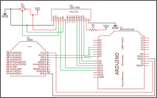
Figure 10. Flow chart of developed PTO torque transducer.
3.4. Measurement of tractor forward speed
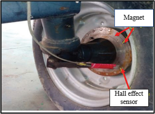
The hall sensor (Magnesensor Technology, India), which was mounted on the tractor’s wheel (Figure ), was used to measure the speed of the tractor in the field (Gupta et al., Citation2019; Hensh et al., Citation2021a; Kumar et al., Citation2017, Nataraj et al., Citation2021). To facilitate RPM measurement, small magnet pieces were fixed to the wheel rim at equal distances. The hall sensor generates a voltage signal when it passes through a magnetic field. The outputs from the sensor were given to the microcontroller, which calculates the speed of the tractor by a developed Arduino program (Smart Projects, India).
Figure 11. A picture of the setup for speed measurement.
4. Testing of developed PTO torque transducer and wireless embedded system
4.1. Validation of developed PTO torque transducer under laboratory conditions
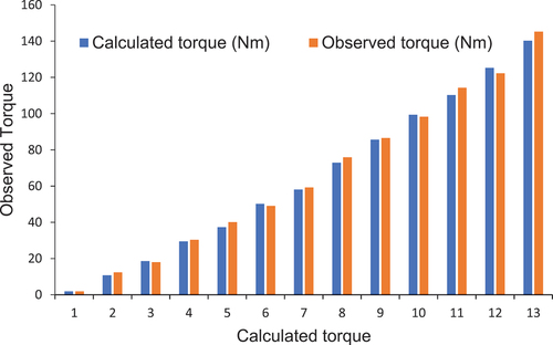
The experiment was carried out in the laboratory of the Department of Agricultural and Food Engineering, IIT Kharagpur. A Samrat 4410 (TAFE, India), 2 WD tractor having 44 hp maximum PTO power, was used to validate the developed PTO torque transducer. The theoretically calculated torque (applied torque) and measured torque obtained from the developed PTO torque transducer were compared. It is observed that measured torque was directly proportional to the theoretically calculated torque. The comparison between actual torque and calculated torque is shown in Figure .
Figure 12. Comparison between calculated torque and observed torque.
4.2. Testing of developed PTO torque transducer under actual field conditions
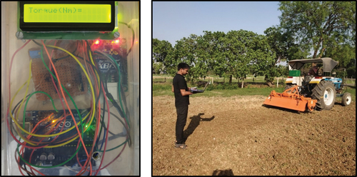
A Samrat 4410, 2 WD tractor having 44 hp maximum PTO power with a rotovator with a working width of 160 cm, was chosen to test the developed PTO torque transducer under field conditions in the research field of the Agricultural and Food Engineering Department, IIT Kharagpur. The tractor was attached to the rotovator along with the developed PTO torque transducer. The program was written in Arduino IDE software, which was uploaded to the memory of the microcontroller of the signal processing cum transmitting unit and receiver cum display unit to activate it. The signal processing cum transmitting unit was wrapped around a developed PTO torque transducer with the help of adhesive tape. For measuring PTO torque, the output signal from the Wheatstone bridge circuit was processed and amplified. The amplified signal is sent to the microcontroller of the signal processing cum transmitting unit. Microcontroller-based circuit transmitted the received signal from the strain gauge to the RF receiver module in real time. The transmitted signal was received by the receiver cum display unit. The observed torque values were displayed on the LCD screen. The field testing of the developed torque transducer is shown in Figure .
Figure 13. Field testing of developed PTO torque transducer using rotavator.
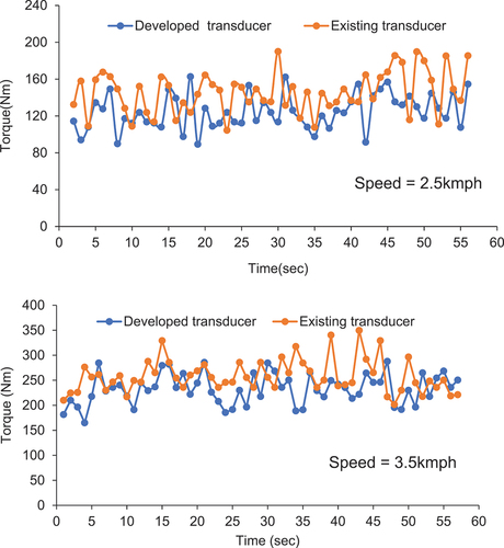
At a speed of 2.5 km/h and a working depth of 100 mm, torque values shown by the torque transducer were in a range of 89–162 Nm, having an average value of 124.25 Nm with a standard deviation of 3.12. At a speed of 3.5kmph and a working depth of 100 mm, torque values shown by the torque transducer were in a range of 181–285 Nm, having an average value of 232.25 Nm with a standard deviation of 2.73. It was found that observed torque increased with increasing tractor forward speed, which is due to soil acceleration increasing with tractor forward speed. The torque value obtained from the developed torque transducer was compared to the torque value obtained from the existing torque transducer (HBM, USA). It is observed that at a speed of 2.5 km/h and 3.5 km/h, average torque values were 145.28 and 273.67 Nm at a working depth of 100 mm for the existing torque transducer, respectively. At 2.5 km/h and 3.5 km/h, the observed torque values of the developed torque transducer differed by 14.48% and 11.88% from the torque value of the existing transducer, respectively, which is shown in Figure . The developed torque transducer measured torque in the range of 0–300 Nm.
Figure 14. Comparison between observed torque from the developed transducer and existing transducer at 2.5 km/h and 3.5 km/h and at a working depth of 100 mm.
4.2.1. Statistical analysis
(1) The observed torque values were also compared with the torque value of the existing torque transducer using a statistical term relative deviation (RD). RD is a measuring accuracy of the system, and it is the mean or average of the absolute percentage errors of forecasts which are calculated from Eq. (1) (Kumar & Pandey, Citation2012).
RD = where the To is the observed torque value of the developed PTO torque transducer, and Te is the torque value obtained from the existing torque transducer. The RD from the test was found to be 8.57% and 9.06% at 2.5 km/h and 3.5 km/h, respectively.
(2) F-test is carried out for equality of variance of two data sets. The value of F is calculated from Eq. (2) (Montgomery, Citation2013).
σ12 and σ22 are the variance of torque value obtained from the developed torque transducer and existing torque transducer, respectively. It has been supposed the null hypothesis H0: σ12–σ22 and alternative hypothesis H1: σ12 ≠ σ22. The F (calculated value) and F (tabular value) are 0.85 and 1.69, respectively, which show that F (calculated value) is lower than F (tabular value). The null hypothesis is accepted. This statistical analysis shows that there is no statistically significant difference between torque value obtained from developed torque transducer and existing torque transducer.
5. Conclusions
From the above discussion, some conclusions are given below.
It is convenient, simple, reliable, and accurate in operation and can be used for any agriculture tractor.
It can transmit signals over RF modules for up to 100 m without interruption.
The developed device helps to know the PTO torque of the tractor in real time.
There is no statistically significant difference between torque value obtained from developed torque transducer and existing torque transducer.
Abbreviations used
PTO Power take-off
2WD Two-wheel drive
RD Relative deviation
Acknowledgments
This research is funded by Agriculture and Food Engineering Dept, IIT Kharagpur, India, (Institute ID: IR-O-U-0573).
Disclosure statement
The authors declare that they have no known competing financial interests or personal relationships that could have appeared to influence the work reported in this paper.
References
- ASABE. (2011) . Agricultural machinery management data. American Society of Agricultural and Biological Engineers.
- Celik, H. K., Cinar, R., Kunt, G., Rennie, A. E. W., Ucar, M., & Akinci, I. (2018). Finite element analysis of a PTO shaft used in an agricultural tractor. Ergonomics International Journal, 2(3). https://doi.org/10.23880/EOIJ-16000147
- Cheong, Y. D., Kim, J. W., Oh, S. H., & Lee, C. W. (1999). Analysis and development of the angular twist type torque-meter. Composite Structures, 47(1–4), 457–13. https://doi.org/10.1016/S0263-8223(00)00010-6
- Choi, C., Ahn, H., Park, Y. J., Kim, S. C., & Yu, J. (2021). Dynamic behavior of an agricultural power take-off driveline for rattle noise reduction: Part 1. Effect of spline tolerance on the power take-off rattle noise. Journal of Terramechanics, 98, 7–14. https://doi.org/10.1016/j.jterra.2021.06.005
- Ghosh, B. N. (1967). The power requirement of a rotary cultivator. Journal of Agricultural Engineering Research, 12(1), 5–12. https://doi.org/10.1016/S0021-8634(67)80030-1
- Grevis-James, I. W. (1979). Matching tractors and implements. Journal of the Department of Agriculture, Western Australia, Series, 20(4), 104–108. https://core.ac.uk/download/pdf/234610651.pdf
- Gupta, C., Tewari, V. K., Kumar, A. A., & Shrivastava, P. (2019). Automatic tractor slip-draft embedded control system. Computers and Electronics in Agriculture, 165, 104947. https://doi.org/10.1016/j.compag.2019.104947
- Hensh, S., Tewari, V. K., & Upadhyay, G. (2021a). An instrumentation system to measure the loads acting on the tractor PTO bearing during rotary tillage. Journal of Terramechanics, 96, 1–10. https://doi.org/10.1016/j.jterra.2021.04.004
- Hensh, S., Tewari, V. K., & Upadhyay, G. (2021b). A novel wireless instrumentation system for measurement of PTO (power take-off) torque requirement during rotary tillage. Biosystems Engineering, 212, 241–251. https://doi.org/10.1016/j.biosystemseng.2021.10.015
- Kheiralla, A. F., Yahya, A., Zohadie, M., & Ishak, W. (2004). Modelling of power and energy requirements for tillage implements operating in Serdang sandy clay loam, Malaysia. Soil and Tillage Research, 78(1), 21–34. https://doi.org/10.1016/j.still.2003.12.011
- Kim, W. S., Chung, S. O., Choi, C. H., Cho, J. S., Choi, D. S., Kim, Y. J., Koo, S. M., Hong, S. J., Kim, Y. J., & Koo, S. M. (2016). Analysis of the PTO torque of a transplanter by planting condition. Journal of Biosystems Engineering, 41(4), 313–318. https://doi.org/10.5307/JBE.2016.41.4.313
- Kim, Y. S., Lee, P. U., Kim, W. S., Kwon, O. W., Kim, C. W., Lee, K. H., & Kim, Y. J. (2019). Strength analysis of a PTO (power take-off) gear-train of a multi-purpose cultivator during a rotary ditching operation. Energies, 12(6), 1100. https://doi.org/10.3390/en12061100
- Kumar, A., & Pandey, K. P. (2012). A device to measure dynamic front wheel reaction to safeguard rearward overturning of agricultural tractors. Computers and Electronics in Agriculture, 87, 152–158. https://doi.org/10.1016/j.compag.2012.06.003
- Kumar, A. A., Tewari, V. K., Nare, B., Chetan, C. R., Srivastava, P., & Kumar, S. P. (2017). Embedded digital drive wheel torque indicator for agricultural 2WD tractors. Computers and Electronics in Agriculture, 139, 91–102. https://doi.org/10.1016/j.compag.2017.05.007
- Kumbhar, H. (2016). Wireless sensor network using Xbee on Arduino platform: An experimental study. In: International Conference on Computing Communication Control and Automation, pp. 1–5. IEEE. https://doi.org/10.1109/ICCUBEA.2016.7860081
- Lee, D. H., Kim, Y. J., Chung, S. O., Choi, C. H., Lee, K. H., & Shin, B. S. (2015). Analysis of the PTO load of a 75 kW agricultural tractor during rotary tillage and baler operation in Korean upland fields. Journal of Terramechanics, 60, 75–83. https://doi.org/10.1016/j.jterra.2015.06.002
- Mahmoud, A. R., Buchele, W. F., & Andrew, J. F. (1972). A strain-gauge, brushless torque meter. Journal of Agricultural Engineering Research, 17(3), 231–235. https://doi.org/10.1016/S0021-8634(72)80026-X
- Montgomery, D. C. (2013). Montgomery design and analysis of experiments (2nd ed.). Wiley.
- Nataraj, E., Sarkar, P., Raheman, H., & Upadhyay, G. (2021). Embedded digital display and warning system of velocity ratio and wheel slip for tractor operated active tillage implements. Journal of Terramechanics, 97, 35–43. https://doi.org/10.1016/j.jterra.2021.06.003
- Orgon, M., Zagajec, L., & Schmidt, I. (2019). Xbee technology: Complex evaluation of radio parameters. In: 11th International Congress on Ultra Modern Telecommunications and Control Systems and Workshops, pp. 1–6. IEEE.https://doi.org/10.1109/ICUMT48472.2019.8970753
- Roeber, J. B., Pitla, S. K., Hoy, R. M., Luck, J. D., & Kocher, M. F. (2017). Tractor power take-off torque measurement and data acquisition system. Applied Engineering in Agriculture, 33(5), 679–686. https://doi.org/10.13031/aea.11994
- Sahitya, G., Balaji, N., Naidu, C. D., & Abinaya, S. (2017, January). Designing a wireless sensor network for precision agriculture using Zigbee. In 2017 IEEE 7th International Advance Computing Conference (IACC) (pp. 287–291). IEEE. https://doi.org/10.1109/IACC.2017.0069
- Sahu, R. K., & Raheman, H. (2008). A decision support system on matching and field performance prediction of tractor-implement system. Computers and Electronics in Agriculture, 60(1), 76–86. https://doi.org/10.1016/j.compag.2007.07.001
- Sarkar, P., Upadhyay, G., & Raheman, H. (2021). Active-passive and passive-passive configurations of combined tillage implements for improved tillage and tractive performance: A review. Spanish Journal of Agricultural Research, 19(4), e0201–e0201. https://doi.org/10.5424/sjar/2021194-18387
- Taylor, R., Shrock, M., & Wertz, K. (1991). Getting the most from your tractor. Cooperative Extension Service. Kansas State University.
- Tuan, K. N. (2019, July). A wireless sensor network for aquaculture using Raspberry Pi, Arduino and Xbee. In 2019 International Conference on System Science and Engineering (ICSSE)(pp. 235–238). IEEE. http://doi.org/10.1109/ICSSE.2019.8823104
- Upadhyay, G., Raheman, H., & Dubey, R. (2022). Novel draught resistance sensing elements for measurement of drawbar power of agricultural machinery. Spanish Journal of Agricultural Research, 20(4), 10. https://doi.org/10.5424/sjar/2022204-19171
- Vigneault, C., AMOUR, G., Buckley, D. J., Masse, D. I., Savoie, P., & Tremblay, D. (1989). A trailer-mounted PTO torquemeter system. Canadian Agricultural Engineering, 31(1), 89–91. https://doi.org/10.3138/cjcrim.31.1.89
- Wang, Y., Wang, L., Zong, J., Lv, D., & Wang, S. (2021). Research on loading method of tractor PTO based on dynamic load spectrum. Agriculture, 11(10), 982. https://doi.org/10.3390/agriculture11100982