
 ?Mathematical formulae have been encoded as MathML and are displayed in this HTML version using MathJax in order to improve their display. Uncheck the box to turn MathJax off. This feature requires Javascript. Click on a formula to zoom.
Abstract
Research and development concerning the electrification of the easily affordable two-wheel vehicle segments operating at low power capacity are significant for a highly populated country like India to attain sustainable transportation. Hence, a novel approach is proposed in this paper focussing on the investigation of bi-directional quasi-Z source inverter (BD-qZSI) using a modified shoot through hysteresis current control (STHCC) loop for brushless direct current (BLDC)-motor-based low power electric vehicle (EV) applications to address this issue. The practical vehicle dynamics, without the computational burden of the complete drive cycle. are suitably established in this research work by achieving different speed and torque conditions with the inclusion of five different modes of operations consisting of three motoring modes (eco, coast, and wrap) and two regenerative braking modes (soft regen and hard regen). The combination of the closed loop speed control of BLDC motor involving PI control in cascade with modified STHCC for the operation of BD-qZSI is analysed in MATLAB/Simulink environement. The performance of the bidirectional power transfer in a single stage including regenerative braking is examined. The results confirm the validity of the proposed system for low-power EV applications. The modified STHCC is easy to implement with quick response compared to other control methods. The performance of single stage BD-qZSI is superior to the conventional two stage converter topologies and to that of Z source inverters. The commutation ripple observed in the torque profile is insignificant in low-power BLDC drive applications. The overall drivetrain efficiency of 84.82% is achieved at rated load condition.
1. Introduction
In highly populated nations like India, transportation sector utilizes large quantity of depleting conventional energy sources like coal and oil, leading to two big problems, namely, excessive exploitation of these sources and the release of residual pollutants to the environment (S et al., Citation2022). The resulting greenhouse gas emission has drastic harmful effect on the overall life sustenance due to climate change. Overall, addressing the environmental impact of transportation requires a multi-faceted approach that involves a combination of technological, behavioral, and policy solutions. Electrification of automobiles is one of the most viable alternative solutions to the existing gasoline engines to this problem. Meanwhile, there is an escalating trend in the research and development of relevant power electronics and battery technology. In addition, new electrical safety policies (Juyal et al., Citation2018) are offered to improve the performance and passenger comfort in EV. Further, the Indian continent has major share of two-wheeler commute segment in transportation. Both in the urban and rural areas, the popularity and the demand, especially, for two wheeler commute segments, are expanding day-by-day for their multifold benefits over larger transporting options in overcrowded traffic due to the convenience, affordability, and minimal requirement of energy (Abu Hanifah et al., Citation2019). To address the need of the hour in such problem, significant research efforts need to be materialized on the powertrain of the EV for two-wheeler segment at low power capacity.
Conventional EV drivetrain consists of appropriately designed motor drive unit connected to the energy storage (Mande et al., Citation2022; Veerendra et al., Citation2021) through bidirectional DC–DC converter (BDC) and voltage source inverter (VSI) (Mallikarjuna Reddy & Samuel, Citation2020; Sankarkumar & Natarajan, Citation2021). In consideration of the low power capacity EV drivetrains, selecting a reliable and cost-effective motor is very critical. The choice is made based on the different features such as efficiency, rotor inertia, noise, speed range, control characteristics, maintenance, cost, power density, torque ripple (Cai et al., Citation2021; Mohanraj et al., Citation2022;). Switched reluctance motor (SRM) (Sun et al., Citation2019), synchronous reluctance motor (Huynh & Hsieh, Citation2018), induction motor (Shukla & Singh, Citation2018), permanent magnet synchronous motor (PMSM) and the BLDC motors are the top choices (Sakunthala et al., Citation2018; Priyanka & Jagadanand, Citation2021; Aiso & Akatsu, Citation2022). PMSM motor is highly efficient with less noise and less torque ripple; however, the cost of rarely available permanent magnets is high and the required control strategies are complex (Ahn et al., Citation2020; Chau et al., Citation2008). SRM also has very complex control application (Koreboina et al., Citation2022). Therefore, at lower power ratings up to 10 kW, BLDC motor with trapezoidal commutation is preferred. It is an effective choice (Rauth & Samanta, Citation2020; Shokri & Naderi, Citation2017) due to its simple algorithm, less maintenance, high efficiency, low noise, high speed range and easy implementation (Kumar & Revankar, Citation2017).
Effective regulation of the motor is equally significant. Sinusoidal commutation and field-oriented control (FOC) may be involved in motor control for high performance motor drives, but they are more complex and expensive (Li & Liu, Citation2018; Yilmaz, Citation2015). Further, hysteresis-band-based current controller is one of the unambiguous current control algorithms as it is comparatively easy to implement with good performance (Shokri & Naderi, Citation2017; Smythe, Citation2021) which is suitable for low power application. It is observed that torque and speed ripples are present in HCC at commutation angles (Li et al., Citation2019; Yilmaz, Citation2015) which is acceptable at lower power capacity.
In EV powertrains, the power demand of themotor drive is supplied by the energy storage system with limited capacity with limited capacity to maintain a better state of charge (SoC) and state of energy (Wang et al., Citation2015). The ratings and capacity of the batteries are decided based on the requirement of the two-wheeler drive capacity. The main possible energy sources in EV are battery, fuel cell, super capacitor and their different combinations. However, fuel cell is not a viable option yet due to its safety issues and space confinement in two wheelers (Ehsani et al., Citation2005; Li et al., Citation2019). Therefore, in this research work, battery alone is considered as energy storage element for the operation of BLDC drive. Out of the different chemistries, lithium-ion is considered as the best option for EV applications at present (Chen & Rincón-Mora, Citation2006: Ehsani et al., Citation2006 & Miller et al., Citation2009) due to its high energy density and no memory effect. Conventionally, the energy from battery is transferred to the load through DC bus through a DC–DC converter and an inverter (Sankarkumar & Natarajan, Citation2021). However, it is found that the variation in the load causes fluctuations in the DC bus voltage (Siwakoti et al., Citation2015). Also, the bidirectional power transfer is essential in EV applications to improve the efficiency of the system to include regenerative braking in motors (Zheng et al., Citation2018).
Researchers tried to improve the performance of the system by replacing two-stage DC–DC converter and inverter with a single stage bidirectional Z-source inverter (ZSI). This simplifies the inverter circuitry control and reliability (Florescu et al., Citation2010; Liu et al., Citation2014) with shoot through mode to increase the voltage gain. Further, the limitations of ZSI are overcome by bi-directional quasi Z source inverter (BD-qZSI) since it has continuous source current and the current stress on the switches are reduced (Liu et al., Citation2016; Singh, Citation2018). Thus, due to the composition and better performance, BD-qZSI is utilized in wide variety of applications (Mande et al., Citation2020). Hence, for drivetrain of the low power capacity, BD-qZSI is one of the best alternatives to overcome the limitations of the conventional voltage source inverter (VSI) and current source inverters (CSI) concerning wide range of voltage gain and number of stages of operation. The available literature is cumulated in Table for the comparison of the research work with the existing work in the EV powertrain.
Table 1. The comparison of the available literature related to EV drivetrain
Research gaps observed from the above-mentioned literature works are listed below:
The existing conventional two-stage bidirectional DC–DC converter with inverter has limited voltage gain. It also requires two separate control strategies for the speed regulation. In addition, it is observed that the DC link voltage is affected from the load variation in the traditional system.
The potential application of single stage BD-qZSI to the low power drivetrain system is not investigated for the two-wheeler segment of EV in the available literature.
Hysteresis current control is not explored for BD-qZSI in the available literature.
Significant effort to include the dynamic performance of the motor drive for two-wheeler EV applications is not carried out based on the drive cycle.
To overcome the above-mentioned limitations, a novel design of single stage BD-qZSI with shoot through hysteresis current control is applied to transfer power from a battery rated at 36 V, 3.6kWh to drive a trapezoidally commutated 1.5 kW BLDC motor with variable load torque in this paper. Five different steps of operation with three motoring modes namely, eco, coast and wrap and two regenerative braking modes namely soft regen and hard regen are introduced to realize static performances of the motor at different speed and different torque conditions. A PI controller is applied for speed control in the proposed system. The potential of BD-qZSI for BLDC drive is investigated in low power, two-wheeler EV application, which is not explored in the available literature. The energy transfer between the source and load is controlled with gating pulses along with the insertion of shoot through for BD-qZSI. The modified shoot-through hysteresis current control (STHCC) is based on the reference of the battery voltage and motor voltage. This is a simple and cost effective yet innovative combination to operate the drivetrain of the EV in low power capacity with good efficiency in high loading condition. Inclusion of regenerative mode improves the efficiency of the system further. The simulation results are presented with suitable interpretation and finally the merits and limitations of the system are summarized. This research adds the following key improvements to the existing literature:
To imitate the practical EV operation dynamics, a feature of five different modes of operation with different speed limiting values and variable torque is introduced in the speed control of the BLDC motor.
The scope of BD-qZSI for BLDC drive with trapezoidal commutation is explored by introducing shoot through duty ratio (STDR) to the Hysteresis Current Control to develop modified STHCC based on the reference of both battery and motor voltages.
The simulation study of single stage bidirectional power transfer through BD-qZSI in closed loop is carried out. The speed control of BLDC using basic PI controller in cascade with modified STHCC for BD-qZSI is the novelty achieved.
This simulation study validates the performance of the proposed system for EV power drive application with following advantages: (1) low and effective cost with considerable efficiency; (2) the control approach is simple and easy to implement compared to other control methods; (3) the regulation of continuous input inrush current at the desired level; (4) boost/buck bidirectional power flow operation in a single stage at different voltage levels
The configuration and the different components of the drive system involved in this research work are discussed in detail with the complete design and methodology further. The rest of the paper is structured in the following manner. Section 2 familiarises the complete drive system along with the energy storage and the load specifications. It also includes the brief narration of modes of operation to enclose the response of the system for different load conditions. The design and operation of the bi-directional quasi Z source inverter topology with the novel modified shoot through hysteresis current control and PI control are explained in Section 3. Section 4 analyses the results of the simulation study with graphical illustration. Section 5 concludes the article.
2. Source and load configuration of the proposed system
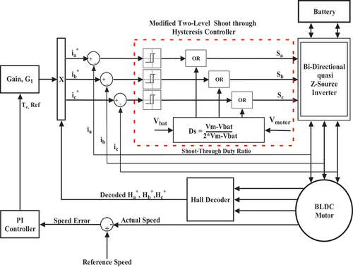
In this research work, the lithium-ion battery with rating of 36 V, 3.6kWh is connected to the BD-qZSI to determine its suitability for the speed control of a 1.5 kW BLDC motor drive with five newly adopted modes of operation with different levels of reference speed limit and variable reference load torque values at different intervals of time. Inclusion of the different modes is an effort to realize the working of the actual EV power drive in the proposed system. The schematic block diagram of the proposed system is shown in Figure . PI controller is applied to regulate the actual speed. Further, the reference current is obtained for STHCC based on the reference torque value to compare it with the actual motor current involving trapezoidal commutation. STHCC generates the shoot through duty ratio (STDR) for BD-qZSI along with gating pulses to its inverter legs at a switching frequency of 25 kHz. The STDR is derived based on the rated motor voltage Vm and nominal battery voltage Vbat using the formula as mentioned below (Liu et al., Citation2016).
Figure 1. Schematic diagram of proposed system for EV application.
2.1. Battery
There are many battery technologies in the market utilized for EV applications such as lead-acid, nickel cadmium, nickel metal hydride and lithium-ion batteries. Out of these, the lithium-ion battery is new generation, which is considered as a better choice due to its high voltage capacity, better energy density, no memory effect with good performance, low self-discharge (Hannan et al., Citation2017). The operation of the battery is highly complex since its reactions to different temperatures, accumulated charge-discharge, charge-discharge rate, and other factors. Some of the parameters such the battery specific energy, specific power, consistency, longevity are still under improvement, and a suitable battery management strategy (Jiang & Zhang, Citation2015) is required. In this research work, lithium-ion battery generic model is considered during MATLAB simulation with the following specifications as mentioned in Table .
Table 2. Battery parameter specifications (Raghunath, Citation2021)
2.2. BLDC motor drive
In three-phase BLDC motor with trapezoidal back EMF, the current drawn by the stator is rectangular in nature to produce constant torque. Back emf waveforms generated are also trapezoidal in nature (Derammelaere et al., Citation2017; Rauth & Samanta, Citation2020). The mathematical modelling and the equations governing the motor operation in steady state and dynamic performance are considered from Hayes & Goodarzi (Citation2018), Krause et al. (Citation2002) and Shokri & Naderi (Citation2017). Design calculation for motor is carried out with following assumptions and parameters of the motor are obtained and presented in Table .
All three windings are concentrated and symmetrical.
Stator resistance and inductances are constant and equal.
Hysteresis and eddy current losses are ignored.
Magnetic saturation and armature reaction are not considered.
Table 3. Motor specifications [15]
2.3. Modes of operation
To include the functioning of variable torque similar to the actual vehicle dynamics, following different modes are introduced in the simulation at different time intervals with different speed and torque specifications of the motor. The exact time intervals are discussed in the result analysis section.
2.3.1. Motoring—eco, coast and warp modes
In the simulation, the mode selection is based on the user input logic. For every mode, the speed limit and current clamp is set to limit the power. There are three modes for motoring namely, eco, coast and warp. The rated torque of the BLDC motor is 4.8 Nm. The different speed limits and the different percentage of rated torque values are given in the three different motoring modes as shown in Table .
Table 4. Modes of operation with specified speed, torque and power ratings
2.3.2. Regen—soft and hard
Regeneration modes are only enabled after the warp mode. A significant amount of energy can be recovered through regenerative braking since it reduces the battery consumption by more than 20% (Van Sterkenburg et al., Citation2011) and the efficiency lies in between 70% (Boretti, Citation2013; Doyle & Muneer, Citation2017). The regenerative braking is disabled in other two motoring modes, which results in freewheeling. The torque applied to motor is monitored all the time. A negative torque is applied to the motor to indicate braking. During braking, the motor acts a generator pushing current in the opposite direction when back emf is higher than supply voltage. With proper gating of IGBT switch S7 of BD-qZSI, the battery charging is controlled. During regenerative braking, the battery current is negative and the voltage is positive. The torque and speed tracking details are mentioned in Table .
3. Investigation of bi-directional quasi z-source inverter with modified shoot-through hysteresis current control approach
3.1. Bi-directional quasi z-source inverter
The transient and the steady-state response of both BD-qZSI and the two-stage DC–DC converter with three phase inverters are comparable under same criteria. The application of BD-qZSI improves the performance of the drive system by overcoming the restrictions of two-stage converter system (Mohammadi et al., Citation2018) such as low voltage stress on inverter leg switches. The results in (Siwakoti et al., Citation2015) also demonstrate that the BD-qZSI efficiency is higher. Also, the BD-qZSI stands out with minimum current ripple in inductor compared to traditional two stage bidirectional topology (Chakraborty et al., Citation2019). BD-qZSI operates like VSI with boost converter during motoring, and as buck converter with CSI in charging conditions (Ayad & Kennel, Citation2017; Ayad et al., Citation2015; Mohammadi et al., Citation2018). It regulates the voltage and current of the energy storage system. In the motoring operation of the drive, the DC voltage from the energy storage system is converted to three-phase voltage through the BD-qZSI to drive the motor load with required torque for achieving the desired speed of the vehicle. In the regenerative braking operation mode, the BLDC motor behaves like a generator and the energy flows in reverse direction to recharge the battery through BD-qZSI working as rectifier. The circuit diagram is depicted in Figure .
Figure 2. BD-qZSI topology.
3.1.1. Design of BD-qZSI
The mathematics of the design of BD-qZSI involves calculation of various parameters such as STDR Ds, voltages across inductors, and capacitors VL1, VL2, VC1, VC2, the output of quasi Z-Source network (qZSN) VPN, the currents IL1, IL2, IC1, IC2, modulation index m, boost factor B, minimum inductance value for continuous current Lm, inductor values L1, L2, capacitances C1 and C2. The following equations determine the design values (Ahn et al., Citation2020; Miller et al., Citation2009). Table presents the parameter specifications obtained from the calculations based on following design equations.
Table 5. Design Calculations of BD-qZSI
It is observed that for a predefined rated power, VPN is inversely proportional to the inductor current.
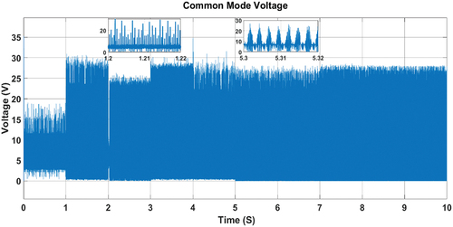
Further, the common mode voltage in the proposed technique is represented as VCM the BD-qZSI which is represented by the following equation
Common mode voltage VCM is significant in motor drives since the leakage current through ground resistance is estimated based on it. VCM is changed by applying different modulation techniques. This common mode voltage induces shaft voltage in the rotor side of the motor. If the voltage induced in the motor shaft exceeds the breakdown voltage of the lubricant in the bearings, it causes a flow of current in the bearings. This is not good for the motor and ultimately leads to motor failure or malfunctioning. Apart from affecting the motor bearings, this current flow also causes damage to the output terminals and the electronic components connected to the motor.
3.1.2. Operation modes of quasi Z-Source inverter
The two functional parts of BD-qZSI are bidirectional quasi z-source network (BD-qZSN) and the three-phase inverter bridge. The topology of qZSN operates in bidirectional mode by replacing the diode of the traditional qZSI by a switch S7 with a parallel diode as shown in Figure ). The BD-QZSN consists of L1, L2, C1, C2, and S7. Generally, three operating states exist namely, the active state (AS), zero state (ZS) and shoot through (ST) state. In ST, both the switches in the same leg of inverter operate simultaneously and this shorting is utilized to boost the dc link voltage Vpn. S7 switch operates in complimentary with the ST state of the bridge. S7 is kept open, the diode develops the voltage, and boost of Vpn is realized. S7 is closed during AS and ZS. The impedance network is highly beneficial since it prevents the short circuit of the source, regulates the inrush currents and voltage boosting.
Figure 3. (a) Shoot through state and (b) non-shoot through state (Guo et al., Citation2013).
The values of L1, L2, C1, C2 are chosen such that L1=L2, and C1= C2 to maintain the symmetry of the structure. The output current of BD-qZSN is given by
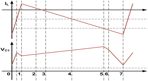
where S1, S3, S5 are closed switches and ia, ib, ic are ac side currents of three phase at the instant. Ipn is the component of AC active power and ipnac is the reactive power component of the current ipn. In BD-qZSI, when S7 is closed, ipnac is able to circulate through only the two capacitors through switch; this improves the working of the battery source (Liu et al., Citation2020). The Ipn traverses through BD-qZSN and is responsible for the energy transfer between DC and AC side. There are total seven intervals of operation of the converter in one switching cycle which can be referred in detail from Guo et al. (Citation2013). The condition of discharge of capacitances and raising inductor currents remains the same. The waveforms of the current through inductor IL1 and voltage across capacitor VC1 in one complete switching cycle including seven modes are presented in Figure . In BD-qZSI, the reverse current flows due to the presence of switch, which results in charging of the battery. In this research, a switching frequency of 25 kHz is applied similar to the reference Liu et al. (Citation2016) since it is appropriate to use IGBTs in the simulation work of EV application.
Figure 4. One complete switching cycle of BD-qZSI.
3.2. Controller design
The speed of the motor is different at different time intervals due to the applied limitation. The speed at any time is determined by the rotor position of the rotor with the help of Hall sensor. This value is compared with the reference speed limit values in the control unit for speed control, which will be discussed in detail in this section.
3.2.1. Estimation of speed error with PI controller
First step in designing the controller is to estimate the obtained speed error. The speed error is generated by comparing the actual speed and the reference speed. This speed error is fed to the PI controller, which compensates the error and generates torque as the output. In this research work, the PI controller is tuned using the Ziegler-Nicols method through which the gains are chosen optimally. The corresponding parameters are Kp = 1.5 and Ki = 0.7. These selected gain values hold good for the entire speed range of operations.
3.2.2. Hysteresis current control
The relation between torque and current is exploited by dividing the torque constant (kt) to obtain the current (Hayes & Goodarzi, Citation2018). The current reference is embedded with the hall sensor values from the decoder block. The reference current and the actual motor current values are compared before feeding to the hysteresis block to generate the reference torque signal.
In a normal two-level HCC, the bandwidth selection plays an important role to regulate the ripple in the output motor torque. It is observed from Talib et al. (Citation2017) that, using a narrow bandwidth, results in high and uncontrolled oscillations and wide bandwidth produce large amount of ripples in the output. If the actual current is exceeding the limit, then the current is cut off to get back to the original reference value on the either side. In this due process, switching frequency may increase drastically and result in uncontrolled switching which further results in large ripples. Hence, the hysteresis band is selected based on soft chopping method (Sridhar & Serbanda, Citation2014). The soft chopping method involves switching either of the upper or lower leg switches with another switch being in the open state. This method is promising because the system performance involves speed and current control. It is very easy to control the current by limiting the current value. This further helps to reduce the ripple in torque and prevents the switching losses. The complete process of standard HCC is narrated as follows.
The compensated torque value obtained from the PI controller is compared with the actual motor torque to generate reference value Te. Further, the Hall sensor reference signals Ha*, Hb*, Hc* decoded from hall sensors Ha, Hb, Hc are multiplied with the torque reference value Te. The relation between torque and current is exploited by dividing the torque constant (kt) to obtain the current. The current reference is embedded with the hall sensor values from the decoder block. The three-phase reference currents ia*, ib*, ic* are produced by dividing the resulting signals from the calculated torque constant (kt). Thus, the three-phase currents are established at the reference value in a simple mathematical approach in HCC. The actual motor current values ia, ib, icare compared with their corresponding references ia*, ib*, ic* before feeding to the hysteresis block. Three two-level hysteresis comparators separately control the individual phase currents based on the bandwidth to generate the switching signals Sa, Sb, Sc to be given to the inverter switches. The comparator decides the band of the hysteresis control, which either increases or decreases the phase current around the reference value so that the error is nothing but the ripple in the current, which is observed in all three phases. The typical HCC method combined with a PI regulator for speed control of a BLDC drive using VSI for a DC source is schematically represented in Figure . The existing HCC controls the output current of the VSI.
Figure 5. Hysteresis current controller for a BLDC drive.
3.2.3 Proposed modified shoot-through hysteresis current control
In this research work, 2% of the rated motor current is considered as the bandwidth of the hysteresis controller to balance the tradeoff between the torque output ripple and the oscillations. The current value of the motor is forced to stay within the range of −0.5 and 0.5 from the reference current based on the torque value to form the hysteresis bandwidth. Further, to explore the voltage boosting in single stage operation of BD-qZSI, inserting shoot-through mode is necessary. This process is carried out by adding (‘OR’ing) shoot through pulses with the existing two-level HCC to generate shoot through duty ratio (STDR). The STDR is generated based on the reference of motor voltage Vm and battery voltage Vbat as represented in EquationEquation 1(1)
(1) . Therefore, the variation of STDR is related only with the changes in Vbat. The schematic of novel modified shoot through insertion in the generation of PWM pulses for BD-qZSI is presented in Figure . The operation of modified STHCC to generate STDR is explained further.
Figure 6. Modified shoot-through hysteresis current controller (STHCC) for a BLDC drive.
The STDR based on EquationEquation 1(1)
(1) is compared with triangular wave generator to produce shoot-through PWM signals. The variable shoot-through PWM signals is inserted through “OR” gate function in the MATLAB simulation to the regular gating signals obtained by the hysteresis band. These gating signals are modified with shoot-through to enable the shorting of the upper and lower switches of an inverter leg to produce maximum current for a certain time. In the due process, the capacitor C1 gets charged that in turn boosts the output voltage of BD-qZSI. This modified approach is termed as shoot-through hysteresis current control or STHCC in this research work. Figure pictorially represents the complete structure of the novel operation approach of the modified STHCC. In this case, the output voltage of the BD-qZSI is higher than the input voltage to achieve higher voltage gain compared to conventional HCC used for VSI.
Figure 7. Detailed schematic of the insertion of shoot through into gate pulses.
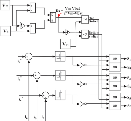
In this simple yet effective method, the notable benefits of the BD-qZSI such as boost/buck bidirectional power flow operation of the voltage in single stage, continuous input current with inrush regulation are established through the reorientation of HCC approach. The essential feature of BD-qZSI to boost the input voltage with the help of capacitor C1 through shoot-through is explored in this research work with STHCC. The commutation ripple is observed in the torque profile because of the finite time taken for the transfer of current from one winding inductance to other in BLDC drive. However, in low power applications, these issues are insignificant.
4. Results and analysis
The proposed drive system with the modified STHCC is simulated using MATLAB/Simulink for a time interval of 10 seconds to study the preliminary performances at static modes accommodating different speed and torque values. Thus, in this research, the computational burden of one complete drive cycle is avoided but the implications of the real-time static performance of the EV drive system is realized. The first 5 seconds are considered for motoring operation and during this interval all the three modes of motoring are included and the battery is discharging. After 5 seconds, the load torque is reversed to allow two modes of regenerative braking. The motor acts as generator to charge the battery.
To demonstrate both motoring and regenerative braking operations, the SoC considered is 60% in this simulation study since the SoC level at the beginning of the practical operation condition is usually 60–80%. The variations of the SoC as per the motoring and regenerative braking in the simulation study are clearly defined in Figure . The initial voltage level of the battery is found to be 38.8 V and the variation in the battery voltage is observed in different time intervals due to trapezoidal commutation, as shown in Figure . Further, the variations in the battery current are proportional to the variations of the load torque and are displayed in Figure . The battery current remains continuous due the inductor L1 which is a feature of BD-qZSI that helps to improve the battery life (Liu et al., Citation2020).
Figure 8. Variation in the state of charge (SoC) level based on operation of the drive.
Figure 9. Battery voltage variation different time intervals of the simulation.
Figure 10. Battery current waveform proportional to the applied torque.
For the total 10 seconds simulation, in motoring mode (0–5 Seconds), the SoC dropped to 53.937%, and in regenerative braking mode (5–10 seconds), the SoC level raised to 59.953%. The battery is discharging during the initial 5 seconds of simulation which is evident of motoring operation. After 5 seconds, the current waveform is negative and the voltage waveform is positive which infer the charging of the battery. In addition, the increase in SoC level is also a clear indication of the charging of battery during braking of the motor.
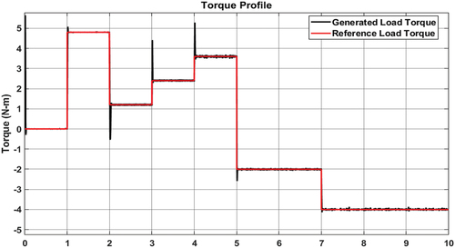
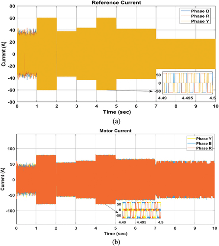
The output of the BD qZSI is given to motor and the responses of current and voltage, as shown in Figure , respectively. The input battery voltage is 36 V and the motor voltage is 48 V, which proves the increase of voltage gain due to the BD qZSI with modified controller as in Figure . The motor is trapezoidally commutated with the STHCC, resulting in spikes and ripples in motor voltage and current waveforms. The variable speed dynamics of the real time vehicle is mimicked by producing different reference speed conditions for the BLDC motor in different time intervals as mentioned in Table . The actual speed regulated using PI controller to generate the reference torque, Te, is depicted in Figure . The speed is varied at different intervals due to the variable torque applied on the rotor. The motor operation with variable reference load torque and the electromagnetic torque developed is shown in Figure .
Figure 11. (a) Motor current and (b) motor voltage waveforms established in the BD-qZSI output.
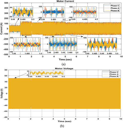
Figure 12. Speed tracking of the motor.
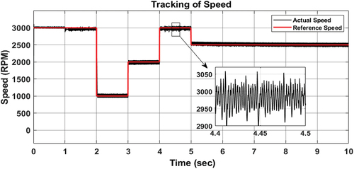
Figure 13. The reference load torque and electromagnetic torque Te in comparison.
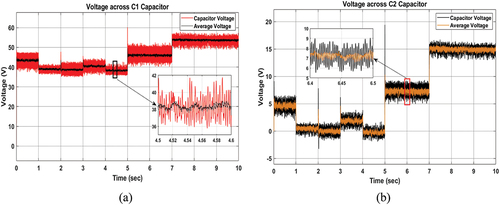
In BD-qZSI module, the inductor currents IL1 and IL2 show the variations according to the variable torque applied to the motor, as shown in Figure . The voltage across the capacitors C1 and C2 vary as per the actual load applied on the motor, as shown in Figure , respectively. At no load condition (0–1 second), as per the calculation, the capacitor C1 should charge to 48 V. In the simulation, the capacitor is charged to 46 V. The motor enters to soft regen mode (II quadrant operation) at 5 seconds, which increases the voltage across the capacitor. Further, at 7 seconds, in hard regen mode, the voltage across C1 (DC link Capacitor) is boosted to a higher value. The voltage across the capacitor C2, as per the calculations is 7 V, but in the simulation, the capacitor charges to 5 V. In regenerative braking operation, the voltage across C2 increases to 8 V at 5 seconds (soft regen mode) and it rises to 15 V at 7 seconds (hard regen). The voltage ripples present in the capacitor voltage waveforms are due to trapezoidal commutation and shoot through phenomenon, which must be neglected in low power applications.
Figure 14. Inductor current across (a) L1 and (b) L2.
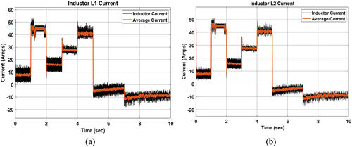
Figure 15. Voltage across (a) capacitor C1 and (b) capacitor C2.
The shoot-through gate pulses are generated by comparing the actual current and reference current obtained from torque reference through the hysteresis band. The STDR obtained from the EquationEquation 1(1)
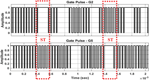
(1) is compared with the triangular wave for amplitude (+0.5 to −0.5) to generate the duty pulses to be added to the gate pulses generated from hysteresis band. Due to this, the output voltage of the BD-qZSI is higher than the input voltage to achieve higher voltage gain compared to conventional VSI. The shoot through gating signal (G2-G5) generation for one of the inverter legs is presented in Figure , highlighting the shoot-through region.
Figure 16. The shoot through switching pulses generated between S2 and S5.
Figures display the concept of relation between Vb and STDR Ds as mentioned in EquationEquation 1(1)
(1) . During the shift of the motor to regenerative braking operation, the battery voltage is increasing whereas STDR Ds is decreasing. Further, the reference current for hysteresis band is obtained from the reference torque and actual motor currents, as presented in Figure , respectively.
Figure 17. (a) The battery voltage Vbat and motor voltage Vm for reference of STHCC shoot through duty ratio Ds.
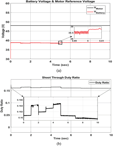
Figure 18. Comparison of (a) reference current and (b) actual current for hysteresis band.
The common voltage VCM obtained from the simulation is shown in Figure . The voltage value is found to be different at different time intervals based on the speed of the motor. The maximum value of VCM is less than 10 V if the voltage spikes are avoided.
Figure 19. Common mode voltage of the proposed system.
The overall system efficiency is very significant from the design perspective. The efficiency during motoring and regenerative braking operation is separately calculated based on the actual input and output power during the entire simulation. The efficiency is calculated from the ratio of total output power at the motor shaft to the input power supplied from the battery according to the following Equation (30).
The output power and the input power during motoring operation in the simulation is presented in Figure . The input and output power in regenerative braking operation are presented in Figure in which the battery behaves as the load for the BLDC generator. Total efficiency in five different modes of operation is also calculated separately for individual time interval based on EquationEquation 30(30)
(30) using graphs (Figures ) with different loading conditions. The efficiency values are tabulated in Table along with speed ripple and torque ripple values in each considered mode of operation at the respective speed and load torque values. It must be noted that battery voltage and battery current in the individual time interval also vary according to the load as shown in Figure .
Figure 20. Motoring operation: (a) output power and (b) input power of the motor.
Figure 21. Regenerative braking operation: (a) input power and (b) output power of the motor.

Table 6. Speed and torque ripple at different motor loading
Initially, for 0–1 second, the motor is made to run-in no-load condition to achieve the rated speed. The rated load torque is applied at 1 second and the overall system efficiency at for this loading condition is about 77%. At 2 seconds, the load torque is reduced to 25% of the rated load and the efficiency of the system drastically reduced to 20% due to under loading of the motor. The maximum power limit is 250 W. In mode 2, the power limit is set to 750 W and with a loading of 50% of the rated load; the system is 43% efficient. In mode 3, the power limit is 1000 W and with a loading of 75% of the rated load torque, the system is 70% efficient. It is observed that, higher the load torque, higher is the overall system efficiency. The efficiency drastically varies based on the loading of the motor. Over loading of the motor leads to oscillations and loss of load, which is observed in simulation. In addition, sudden reduction in the torque causes overshoot in the negative direction resulting in momentary regenerative braking since torque becomes negative.
The drive has two modes in regeneration mode. The soft regen mode limits the power obtained during regenerative braking to 525 watts and hard regen power limit is 1150 watts from the motor side. The efficiency of energy recovery during regenerative braking recovery is based on the control strategy and lies in between 20% and 70% as mentioned in section 2.3; 18% efficiency in soft regen mode and 38% efficiency in hard regen mode are observed in this simulation study. It is observed that as the braking torque increases, the efficiency of the recovery also increases since the heat energy released from the braking is more. Regenerative braking is a transient process and most of the energy is lost in the conversion process. The input power (the power from the motor to the battery) in soft regen mode is around 90 watts and in hard regen mode, it is around 280 watts. Additionally, the optimization of control algorithm is necessary to improve the power recovery level as per the actual practical conditions.
The overall system efficiency calculated based on battery power and the output power at the motor mainly depends on the load. If the load is reduced, the performance of the system is also reduced as inferred from the simulation results. It is observed that the torque ripple is more at full load and gradually reduces as the load decreases. The speed ripple and torque ripples are minimum at half-loading condition or 50% of the rated torque condition.
5. Conclusion
In this paper, the potential of the modelled bidirectional quasi Z-source inverter for low power EV application is explored with battery (energy storage) and BLDC motor using modified shoot-through hysteresis current control in cascade with PI controller in MATLAB/Simulink platform. The essential feature of the bi-directional quasi-Z-source inverter to boost the input voltage with the help of capacitor C1 through shoot-through is explored in this research work with modified shoot-through hysteresis current control effectively. The regulation of continuous input inrush current is another notable benefit of employing the bi-directional quasi-Z-source inverter through the simple yet effective reorientation of the hysteresis current control approach. Initially, five different modes of motoring and regenerative braking operation of the BLDC motor are introduced for the application of different load torque and different speed limits to mimic the real-world EV operating conditions. The strategy of inculcating different load torque profile in different time intervals of the simulation with different speed limit helps to understand the feasibility and the static performance of the proposed system in real time. Further, the performance of the proposed system is investigated and it is inferred that the motor speed control is achieved by applying a single stage bi-directional quasi Z-source inverter with modified hysteresis current control being satisfactory at the low power (1.5 kW) stage. The efficiency of the complete drive system is observed to be 84.82% at rated torque condition. The drive is equipped with regeneration capability, which can recover up to 500 W, as recognizable from the battery current and SoC variations. The drive control logic is designed in such a way that, whenever the motoring operation is absent, the regeneration mode is turned on automatically. This proposed system involves a simple and novel control method, which is cost effective, easy to implement and best suited for the low power EV applications with bidirectional power flow. The performance of the proposed system against the dynamics of the EV drive cycle can be considered as the extension for future works in this domain.
Disclosure statement
No potential conflict of interest was reported by the author(s).
Additional information
Funding
References
- Abu Hanifah, R., Toha, S. F., Mohamad Hanif, N. H. H., & Kamisan, N. A. (2019). Electric motorcycle modeling for speed tracking and range travelled estimation. Institute of Electrical and Electronics Engineers Access, 7, 26821–25. https://doi.org/10.1109/ACCESS.2019.2900443
- Ahmad, S., Uddin, R., Ganie, Z. A., Anees, A. S., & Bakhsh, F. I. (2022). Low frequency operation and dsPIC micro-controller implementation for multilevel quasi Z source inverter in photovoltaic application. Distributed Generation & Alternative Energy Journal, 37(4), 929–958. https://doi.org/10.13052/dgaej2156-3306.3743
- Ahmad, S., Uddin, R., Ghanie, Z. A., & Tasneem, A. (2019). Close loop control of quasi Z-Source inverter in grid connected PV system. Proceedings - 2019 International Conference on Electrical, Electronics and Computer Engineering, UPCON 2019, (1), 1–6. https://doi.org/10.1109/UPCON47278.2019.8980075
- Ahn, H., Park, H., Kim, C., & Lee, H. (2020). A review of state-of-the-art techniques for PMSM parameter identification. Journal of Electrical Engineering and Technology, 15(3), 1177–1187. https://doi.org/10.1007/s42835-020-00398-6
- Aiso, K., & Akatsu, K. (2022). Performance comparison of high-speed motors for electric vehicle. World Electric Vehicle Journal, 13(4), 57. https://doi.org/10.3390/wevj13040057
- Ayad, A., Hanafiah, S., and Kennel, R. (2015, May) A comparison of quasi-z-source inverter and traditional two-stage inverter for photovoltaic application. Proceedings of PCIM Europe 2015; International Exhibition and Conference for Power Electronics, Intelligent Motion,Renewable Energy and Energy Management, Nuremberg, Germany (pp. 19–21).
- Ayad, A. and Kennel, R. (2017). A comparison of quasi-Z-source inverters and conventional two-stage inverters for PV applications. EPE Journal (European Power Electronics and Drives Journal), 27(2), 43–59. https://doi.org/10.1080/09398368.2017.1317136
- Boretti, A. (2013). Analysis of the regenerative braking efficiency of a latest electric vehicle. SAE Technical Papers, 12. https://doi.org/10.4271/2013-01-2872
- Cai, W., Wu, X., Zhou, M., Liang, Y., and Wang, Y. (2021). Review and development of electric motor Systems and electric powertrains for new energy vehicles. Automotive Innovation, 4(1), 3–22. https://doi.org/10.1007/s42154-021-00139-z
- Chakraborty, S., Vu, H. N., Hasan, M. M., Tran, D. D., El Baghdadi, M., & Hegazy, O. (2019). DC-DC converter topologies for electric vehicles, plug-in hybrid electric vehicles and fast charging stations: State of the art and future trends. Energies, 12(8), 1569. https://doi.org/10.3390/en12081569
- Chau, K. T., Chan, C. C., & Liu, C. (2008). Overview of permanent-magnet brushless drives for electric and hybrid electric vehicles. IEEE Transactions on Industrial Electronics, 55(6), 2246–2257. https://doi.org/10.1109/TIE.2008.918403
- Chen, M., & Rincón-Mora, G. A. (2006, June). Accurate electrical battery model capable of predicting runtime and I-V performance. IEEE Transactions on Energy Conversion, 21(2), 504–511. https://doi.org/10.1109/TEC.2006.874229
- Derammelaere, S., Haemers, M., De Viaene, J., Verbelen, F., and Stockman, K. (2017). A quantitative comparison between BLDC, PMSM, brushed DC and stepping motor technologies. Proceedings of the 19th International Conference on Electrical Machines and Systems, ICEMS 2016, Chiba, Japan.
- Doyle, A., & Muneer, T. (2017). Traction energy and battery performance modelling. In Electric vehicles: Prospects and challenges (pp. 93–124). Elsevier Inc. https://doi.org/10.1016/B978-0-12-803021-9.00002-1
- Ehsani, A., Gao, M., Gay, Y., & Emadi, S. E. (2005). Modern electric, hybrid electric, and fuel cell vehicles fundamentals, theory, and design (2005th ed.). CRC Press.
- Florescu, A., Stocklosa, O., Teodorescu, M., Radoi, C., Stoichescu, D. A., & Rosu, S. (2010). The advantages, limitations and disadvantages of Z-source inverter. Proceedings of the International Semiconductor Conference, CAS, 2(1), 483–486. https://doi.org/10.1109/SMICND.2010.5650503
- Guo, F., Fu, L., Lin, C. H., Li, C., Choi, W., & Wang, J. (2013). Development of an 85-kW bidirectional quasi-Z-source inverter with DC-link feed-forward compensation for electric vehicle applications. IEEE Transactions on Power Electronics, 28(12), 5477–5488. https://doi.org/10.1109/TPEL.2012.2237523
- Hannan, M. A., Lipu, M. S. H., Hussain, A., & Mohamed, A. (2017). A review of lithium-ion battery state of charge estimation and management system in electric vehicle applications: Challenges and recommendations. Renewable and Sustainable Energy Reviews, 78(August), 834–854. https://doi.org/10.1016/j.rser.2017.05.001
- Hayes, J. G., & Abas Goodarzi, G. (2018). Electric powertrain energy systems, power electronics and drives for hybrid, electric and fuel cell vehicles. https://doi.org/10.1002/9781119063681
- Huynh, T. A., & Hsieh, M. F. (2018). Performance analysis of permanent magnet motors for electric vehicles (EV) traction considering driving cycles. Energies, 11(6), 1385. https://doi.org/10.3390/en11061385
- Hu, R., Zeng, J., Liu, J., & Eric Cheng, K. W. (2021). A nonisolated bidirectional DC-DC converter with high voltage conversion ratio based on coupled inductor and switched capacitor. IEEE Transactions on Industrial Electronics, 68(2), 1155–1165. https://doi.org/10.1109/TIE.2020.2967667
- Jiang, J., & Zhang, C. (2015). Fundamentals and applications of lithium-ion batteries in electric drive vehicles (1st ed.). John Wiley & Sons, Ltd.
- Juyal, S. (2018). Zero Emission Vehicles (ZEVs): Towards a Ploicy Framework. [Online]. http://niti.gov.in/writereaddata/files/document_publication/EV_report.pdf
- Ke, G., Yan, C., Gan, Y., and Lin, Z. (2011). Control of z-source photovoltaic inverter for grid-connected based on constant-frequency hysteresis current control. In Conference Record of the IEEE Photovoltaic Specialists Conference (pp. 002340–002345). https://doi.org/10.1109/PVSC.2011.6186422
- Koreboina, V. B., Narasimharaju, B. L., & Vinod Kumar, D. M. (2022). Performance investigation on ANFIS and FFNN assisted direct and indirect PV-fed switched reluctance motor water pumping system. International Journal of Modelling and Simulation, 42(2), 255–267. https://doi.org/10.1080/02286203.2021.1875288
- Krause, P. C., Wasynczuk, O., & Sudhoff, S. D. (2002). Analysis of electric machinery drive systems (2nd ed.). Purdue University: IEEE Press, Wiley Inter-Science.
- Kumar, M. S., & Revankar, S. T. (2017). Development scheme and key technology of an electric vehicle: An overview. Renewable and Sustainable Energy Reviews, 70, 1266–1285. https://doi.org/10.1016/j.rser.2016.12.027
- Li, Z., Khajepour, A., & Song, J. (2019, September). A comprehensive review of the key technologies for pure electric vehicles. Energy, 182, 824–839. https://doi.org/10.1016/j.energy.2019.06.077
- Li, L., & Liu, Y. (2018). Design and simulation of permanent magnet synchronous motor control system. AIP Conference Proceedings, 1971(July). https://doi.org/10.1063/1.5041173
- Liu, Y., Abu-Rub, H., Ge, B., Blaabjerg, F., Ellabban, O., & Loh, P. C. (2016). Impedance source power electronic converters (1st ed.). John Wiley & Sons, Ltd. https://doi.org/10.1002/9781119037088
- Liu, Y., Ge, B., Abu-Rub, H., & Peng, F. Z. (2014). Overview of space vector modulations for three-phase Z-Source/quasi-z- source inverters. IEEE Transactions on Power Electronics, 29(4), 2098–2108. https://doi.org/10.1109/TPEL.2013.2269539
- Liu, W., Yang, Y., Kerekes, T., Vinnikov, D., & Blaabjerg, F. (2020). Inductor Current ripple analysis and reduction for quasi-Z-Source inverters with an improved ZSVM6 strategy. IEEE Transactions on Power Electronics, 36(7), 7693–7704. https://doi.org/10.1109/TPEL.2020.3043102
- Mallikarjuna Reddy, B. and Samuel, P. (2020). Analysis, modelling and implementation of multi-phase single-leg DC/DC converter for fuel cell hybrid electric vehicles. International Journal of Modelling and Simulation, 40(4), 279–290. https://doi.org/10.1080/02286203.2019.1610689
- Mande, D., Trovão, J. P., & Ta, M. C. (2020). Comprehensive review on main topologies of impedance source inverter used in electric vehicle applications. World Electric Vehicle Journal, 11(2), 01. https://doi.org/10.3390/WEVJ11020037
- Mande, D., Trovão, J. P. F., Ta, M. C., & Van Do, T. (2022). Dual-source bidirectional quasi-Z-Source inverter development for off-road electric vehicles. World Electric Vehicle Journal, 13(9), 174. https://doi.org/10.3390/wevj13090174
- Mawlikar, M. A. and Nair, S. S. (2017). A comparative analysis of Z source inverter and DC- DC converter fed VSI. Proceedings of the 2017 International Conference on Nascent Technologies in Engineering (ICNTE), Vashi, India (pp. 0–5).
- Miller, J. M., Bohn, T., Dougherty, T. J., and Deshpande, U. (2009). Why hybridization of energy storage is essential for future hybrid, plug-in and battery electric vehicles. In 2009 IEEE Energy Conversion Congress and Exposition, ECCE 2009 (pp. 2614–2620). https://doi.org/10.1109/ECCE.2009.5316096
- Mohammadi, M., Moghani, J. S., & Milimonfared, J. (2018). A novel dual switching frequency modulation for Z-Source and quasi-Z-Source inverters. IEEE Transactions on Industrial Electronics, 65(6), 5167–5176. https://doi.org/10.1109/TIE.2017.2784346
- Mohanraj, D., Gopalakrishnan, J., Chokkalingam, B., & Mihet-Popa, L. (2022). Critical aspects of electric motor drive Controllers and mitigation of torque ripple - Review. Institute of Electrical and Electronics Engineers Access, 10(April), 73635–73674. https://doi.org/10.1109/ACCESS.2022.3187515
- Panfilov, D., Husev, O., Blaabjerg, F., Zakis, J., & Khandakji, K. (2016). Comparison of three-phase three-level voltage source inverter with intermediate dc-dc boost converter and quasi-Z-sourceinverter. IET Power Electronics, 9(6), 1238–1248. https://doi.org/10.1049/iet-pel.2015.0539
- Pan, X., Pang, Z., Liu, Y., Yin, S., & Ju, C. (2020). Enhanced-boost bidirectional quasi-Z-Source inverter with novel active switched inductor cells. IEEE Journal of Emerging and Selected Topics in Power Electronics, 8(3), 3041–3055. https://doi.org/10.1109/JESTPE.2019.2916832
- Peng, F. Z., Joseph, A., Wang, J., Shen, M., Chen, L., Pan, Z., Ortiz-Rivera, E., & Huang, Y. (2005). Z-Source inverter for motor drives. IEEE Transactions on Power Electronics, 20(4), 857–863. https://doi.org/10.1109/TPEL.2005.850938
- Priyanka, C. P., & Jagadanand, G. (2021). Design and analysis of BLDC motor for electric vehicle application. In V. L. N. Komanapalli, N. Sivakumaran, & S. Hampannavar (Eds.), Advances in automation, signal processing, instrumentation, and control lecture notes in electrical engineering (pp. 2421–2429). Springer. https://doi.org/10.1007/978-981-15-8221-9
- Rabkowski, J. (2007). The bidirectional Z-source inverter for energy storage application. 2007 European Conference on Power Electronics and Applications, EPE. https://doi.org/10.1109/EPE.2007.4417265
- Raghunath, S. (2021). Hardware design considerations for an electric BicycleUsing a BLDC motor.
- Rauth, S. S. and Samanta, B. (2020). Comparative analysis of IM/BLDC/PMSM drives for electric vehicle traction applications using ANN-Based FOC. Proceedings of the 2020 IEEE 17th India Council International Conference, INDICON 2020, New Delhi, India. https://doi.org/10.1109/INDICON49873.2020.9342237
- Sakunthala, S., Kiranmayi, R., and Mandadi, P. N. (2018). A study on industrial motor drives: Comparison and applications of PMSM and BLDC motor drives. Proceedings of the 2017 International Conference on Energy, Communication, Data Analytics and Soft Computing, ICECDS 2017 Chennai, India (pp. 537–540). https://doi.org/10.1109/ICECDS.2017.8390224
- Sankarkumar, R. S. and Natarajan, R. (2021). Energy management techniques and topologies suitable for hybrid energy storage system powered electric vehicles: An overview. International Transactions on Electrical Energy Systems, 31(4), 1–30. https://doi.org/10.1002/2050-7038.12819
- Shokri, G. and Naderi, E. (2017). Research on simulation and modeling of simple and cost-effective BLDC motor drives. International Journal of Modelling and Simulation, 37(1), 15–24. https://doi.org/10.1080/02286203.2016.1195665
- Shukla, S. and Singh, B. (2018). Solar powered sensorless induction motor drive with improved efficiency for water pumping. IET Power Electronics, 11(3), 416–426. https://doi.org/10.1049/iet-pel.2017.0452
- Sikora, A., & Wo´zniak, M. (2021). Impact of current pulsation on BLDC motor parameters. Sensors, 21(2), 1–18. https://doi.org/10.3390/s21020587
- Singh, S. A. (2018). Design and implementation of a single phase modified Z-source inverter topology for photovoltaic/Grid interconnected DC charging applications.
- Siwakoti, Y. P., Peng, F. Z., Blaabjerg, F., Loh, P. C., & Town, G. E. (2015). Impedance-source networks for electric power conversion part I: A topological review. IEEE Transactions on Power Electronics, 30(2), 699–716. https://doi.org/10.1109/TPEL.2014.2313746
- Siwakoti, Y. P., Peng, F. Z., Blaabjerg, F., Loh, P. C., Town, G. E., & Yang, S. (2015). Impedance-source networks for electric power conversion part II: Review of control and modulation techniques. IEEE Transactions on Power Electronics, 30(4), 1887–1906. https://doi.org/10.1109/TPEL.2014.2329859
- S, K. V., Michael, L. K., Hungund, S. S., Fernandes, M., & Cameselle, C. (2022). Factors influencing adoption of electric vehicles – A case in India. Cogent Engineering, 9(1). https://doi.org/10.1080/23311916.2022.2085375
- Smythe, R. J. (2021). Current control. Arduino in Science. https://doi.org/10.1007/978-1-4842-6778-3_10
- Sridhar, M., & Serbanda, M. (2014). Torque hysteresis control of BLDC drives for EV application by using fuzzy logic controller. International Journal of Engineering and Technical Research (IJETR), 2(9), 350–357.
- Sun, Q., Wu, J., Gan, C., Si, J., Guo, J., & Hu, Y. (2019). Cascaded multiport converter for SRM-based hybrid electrical vehicle applications. IEEE Transactions on Power Electronics, 34(12), 11940–11951. https://doi.org/10.1109/TPEL.2019.2909187
- Suryakant, M. S., & Singh, M. (2018). Performance analysis of PMSM drive using hysteresis current controller and PWM current controller. 2018 IEEE International Students’ Conference on Electrical, Electronics and Computer Science, SCEECS 2018, (1), 1–5. https://doi.org/10.1109/SCEECS.2018.8546862
- Talib, M. H. N., Isa, S. N. M., Hamidon, H. E., Ibrahim, Z., and Rasin, Z. (2017). Hysteresis current control of induction motor drives using dSPACE DSP controller. Proceedings of the PECON 2016 - 2016 IEEE 6th International Conference on Power and Energy, Conference Proceeding, Melaka, Malaysia (pp. 522–527. https://doi.org/10.1109/PECON.2016.7951617
- Van Sterkenburg, S., Rietveld, E., Rieck, F., Veenhuizen, B., and Bosma, H. (2011). Analysis of regenerative braking efficiency - A case study of two electric vehicles operating in the Rotterdam area. Proceedings of the 2011 IEEE Vehicle Power and Propulsion Conference, VPPC 2011, Chicago, IL, USA (pp. 3–8). https://doi.org/10.1109/VPPC.2011.6043109
- Veerendra, A. S., Mohamed, M. R., Leung, P. K., and Shah, A. A. (2021). Hybrid power management for fuel cell/supercapacitor series hybrid electric vehicle. International Journal of Green Energy, 18(2), 128–143. https://doi.org/10.1080/15435075.2020.1831511
- Wang, Y., Zhang, C., Chen, Z., Xie, J., & Zhang, X. (2015, May). A novel active equalization method for lithium-ion batteries in electric vehicles. Applied Energy, 145, 36–42. https://doi.org/10.1016/j.apenergy.2015.01.127
- Yilmaz, M. (2015, August 12). Limitations/Capabilities of electric machine technologies and modeling approaches for electric motor design and analysis in plug-in electric vehicle applications. Renewable and Sustainable Energy Reviews, 52, 80–99. https://doi.org/10.1016/j.rser.2015.07.033
- Zheng, C., Li, W., and Liang, Q. (2018). An energy management strategy of hybrid energy storage Systems for electric vehicle applications. IEEE Transactions on Sustainable Energy, 9(4), 1880–1888. https://doi.org/10.1109/TSTE.2018.2818259