
 ?Mathematical formulae have been encoded as MathML and are displayed in this HTML version using MathJax in order to improve their display. Uncheck the box to turn MathJax off. This feature requires Javascript. Click on a formula to zoom.
Abstract
Considering the current growth of design and development activities in micro/mini-Unmanned Aerial Vehicles (UAVs), there is a significant need for thin, durable and lightweight composites for their structural applications. Robust and impact-resistant materials are deemed mandatory concerning the harsh operational conditions where these UAVs are employed. Numerical models for composite materials at various loading conditions can bring up tremendous pace in various design and manufacturing aspects of such competent and tailored engineering materials. Numerical simulations of low velocity flatwise Charpy impact are performed on carbon/aramid hybrid laminates. The modelling is based on representative volume element (RVE) micro-scale property homogenisation in ANSYS Workbench, followed by macroscale impact analysis in ABAQUS/EXPLICIT. The damage propagation was determined using the Hashin failure criteria. The numerically predicted results were validated against the experimental data concerning the energy absorbed and impact strength. The results provided by the modelling are in good correlation with the experimental observations. The numerically obtained force-time data correlated the damage propagation and failure modes observed in the post-impact damage morphology in the laminate during the non-instrumented Charpy test.
1. Introduction
Polymer composites have firmly established themselves in high-end applications, thanks to their exceptional specific strength. These lightweight materials empower engineers to craft slender yet sturdy structures, maintaining optimal performance (Andrews Zachariah and Satish Shenoy, Citation2021). Carbon fibre reinforced plastic (CFRP) finds extensive use in micro/mini-Unmanned Aerial Vehicles (UAVs) and aviation sectors for structural components. However, their many advantages come with intricately complex and multifaceted impact behavior. They are particularly sensitive to through-thickness damage, significantly affecting their energy absorption properties and residual load-bearing capacity.
Hybridisation using High Strain Materials (HSM) is a proven strategy in tailoring impact strength to CFRP laminates (Andrews Zachariah and Satish Shenoy, Citation2021). HSM possess more excellent toughness, tenacity and strain to failure than Low Strain Material (LSM) like carbon fibres (Andrews Zachariah et al., Citation2021; Swolfs et al., Citation2014). Widely used HSM fibres for hybrid polymer composites are glass and aramid fibres (Fotouhi et al., Citation2017). HSM fibres are generally added with carbon fibres at two approaches, namely inter-ply and intra-ply levels. In the inter-ply method, the hybrid layers are added as exclusive layers to the primary reinforcement layer. The intra-ply method follows a methodology of mixing two or more fibres within a strand or in the warp and weft directions. The laminate level property and overall stacking balance are not compromised in the inter-ply approach. The intra-ply approach is comparatively complicated and laborious than the inter-ply approach, where the HSM is added at the individual layer, yarn by yarn or in warp and weft direction.
A good balance of the in-plane mechanical property is recommended for impact-resistant laminates. The woven fabric with uniform distribution of reinforcements along the weft and warp is reported to have excellent impact performance than unidirectional (UD) and cross-ply laminates (Naik et al., Citation2000). However, the laminate property towards the thickness direction is of prime importance when evaluating a composite material’s overall impact performance. The impact forces encountered by a laminate employed in the structural component are as an instantaneous dynamic load acted towards the thickness direction with impact waves travelling towards the direction of impact. The impact scenarios are categorised into low, medium and ballistic based on the velocity and energy at which the target incident on the laminate. Low-velocity impacts (LVIs) are unique as they create serious safety issues due to the invisible but extended damage in the composite structure during routine visual inspections (Zachariah et al., Citation2021). The damage caused due to LVI is categorised as Barely Visible Impact Damage (BVID). However, BVID is insidious when the structure is put back to service. These LVI-damaged structures may undergo a catastrophic failure when they persist and are ignored.
The experimental tests for impact study are broadly classified as low, medium and high based on the velocity range of impact. The Charpy and drop tower impact are the two widely performed standard LVI tests (Kosedag and Ekici, Citation2022). A large amount of data about the impact performance of polymer composites is available in literature at various loading boundary conditions and loading rates. However, the scaling or generalisation of test results is problematic since the impact design methodology largely depends on the experimental boundary conditions and the laminate stacking setup (Shah et al., Citation2019). The commonly reported failure modes in the laminates exposed to impact loadings, such as delamination, tensile matrix fracture and fibre fracture are significantly dependent on the reinforcement type, matrix type, layup and laminate thickness. However, the test data obtained from the impact study was also significantly influenced by the impact parameters like the loading velocity, energy, projectile type and impactor geometry.
The type of damage information obtained from a Charpy test on composite materials is limited to the absorbed energy and impact strength. However, they allow valuable comparative data that are determined simply and effectively. Moreover, the Charpy test is a fast and cost-efficient comparison tool compared to the expensive and complex experimental setup of the drop weight impact tower. Caminero et al. (Citation2016) investigated the effect of stacking sequence on Charpy impact test UD and cross-ply laminates and concluded that cross-ply and multidirectional laminates absorbed more impact energy due to better impact strength. The hybridisation of LSM, such as carbon fibre laminates with a high HSM like para-aramid fibres improves the impact performance. Erkliğ and Bulut (Citation2017) have studied the impact performance of hybrid glass/kevlar laminates using the Charpy impact test, and the results conclude the improvement of impact performance in laminates with kevlar having the highest impact strength. Zachariah et al. (Citation2020) experimentally investigated the dynamic behaviour of woven carbon/kevlar thin hybrid laminates using the Charpy impact test to establish the influence of HSM in imparting impact response concerning the location, orientation and number of aramid layers. The presence of angle plies promotes delamination; however, the impact strength and absorbed energy are more as the fraction of aramid increases. Majority of reported Charpy impact tests results are obtained from experimental investigations. However, there is need for further research into numerical prediction and validation of these test results.
The advancements in numerical modelling techniques aid the designers with various material modelling and testing tasks to partly alternate the usually extensive, expensive and time-consuming experimental procedures (Metin & Avcı, Citation2021; Liu et al., Citation2021). The material property assignment in polymer composites is of great challenge when compared to other homogeneous materials. Combining of the matrix, fibre and the fibre-matrix interphase makes it more complex to generalise and standardise the lamina level property. It is difficult to experimentally determine such orthotropic composite moduli, specifically when it includes the determination of the transverse, shear and longitudinal moduli. Therefore, finite element methods (FEMs) based numerical simulations are essential to substantiate the viability of the laminate designs (Rawat et al., Citation2017). Methods to numerically estimate the elastic properties of composite materials include analysis of an RVE equivalent to a periodic fibre packing sequence (Dong & Sun, Citation2009; Siddiqui & Sun, Citation2017; CRK, 2021). Determination of unit-cell properties at the microscale level and homogenising the unit-cell property to individual lamina effectively captures the elastic properties of a composite material. Microscale unit-cell homogenisation prevents the shortcomings of carrying experimental values for numerical analysis (Shi et al., Citation2012; Denning, Citation2004; Marszałek et al., Citation2020; Dixit et al., Citation2013) reported the agreement of unit-cell analysis for finding the necessary micromechanical properties of composite laminates for multiscale analysis. The values from the RVE analysis are higher compared to the actual experiment due to the warpage in fabrics during fabrication and the loss of properties during the weaving process.
In the micro-scale analysis, RVE models are with only one fibre enveloped by a matrix. The fibre volume fraction for RVE is determined based on the overall fibre volume fraction in the lamina (Pascal et al., Citation2018; Papakaliatakis & Karalekas, Citation2010; Sørensen, Citation2017). Naghdinasab et al. (Citation2018) studied the degradation of material properties in composite RVE during damages. The RVE models can obtain elastic properties of composite unit-cell that can be homogenised and used to determine laminae properties (Rayhan and Rahman, Citation2020). According to the literature, RVE-based numerical simulation in hybrid composites with multi-moduli fabrics is not extensively reported. There is a substantial gap in the available studies on the comprehensive data on the influence of HSM fabric in CFRP laminates with overall thickness below 3 mm, which are suitable for impact-resistant structural applications in small, micro/mini UAVs (Ramesh and Lal, Citation2020).
Hence in this work, the numerical model of the flatwise Charpy impact test is developed, and a FEA of the impact test is performed in ABAQUS/EXPLICIT. A macroscale approach is followed with laminae material properties determined through RVE analysis of the composite microstructure. The numerical results and material damage behaviour are compared with the experimental Charpy impact data reported by this author, and subsequently, the results are interpreted to the experimental strength parameters (Zachariah et al., Citation2020). The results reported in this study will better identify the failure criteria, damage modes and resulting damage morphology of the Charpy test in laminated hybrid composites.
This article focuses on the implementation of microscale representative volume element (RVE) to perform macroscale laminate analysis using FEMs, for the LVI, Charpy test. Later the energy absorbed during the impact process from numerical simulations are compared and validated with experimental results. The correlation of numerically predicted force-time response against the damage morphology of the post-impact sample is also discussed.
2. Experimental methodology – LVI Charpy test
The Charpy impact test is a three-point bending at a dynamic loading scenario. It is performed to study energy absorption and impact strength. This test provides information on the impact strength or impact toughness which is commonly identified as the threshold of force acting per unit area before the material fracture. When the impact energy crosses a threshold value that the specimen can withstand, the material fails by fracture, delamination or tear thereby providing an understanding that the material has exceeded its impact strength.
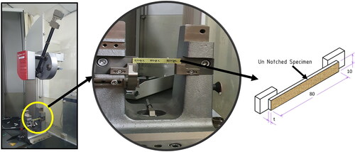
In this work, the Charpy impact test was performed in the Zwick/Roell HIT50P with an impact energy of 7.5 J at KONSPEC, Karnataka, India as shown in . The un-notched specimen was mounted flatwise and the impact load was directed towards the in-plane face of the laminate as shown in (International Organization for Standardization, Citation2000). The impact strength is calculated using EquationEquation (1)
(1)
(1) as per standard ISO179-1 (Zachariah et al., Citation2020).
(1)
(1)
Figure 1. Charpy impact test experimental setup (Zachariah et al., Citation2020).
In the above equation, and
represent the energy absorbed, thickness and width of the specimen, respectively. The pendulum striker velocity for this study was maintained at 3.807 m/s. Value of
is acquired as experimental output data.
3. Methodology for the numerical study
The numerical study has been conducted in two levels. In the first level, microscale analysis of a unit-cell of the composite lamina was performed. The elastic properties determined from the Level 1 analysis have been homogenised as the laminae level property for the macroscale analysis at Level 2 as shown in . A schematic of the numerical methodology is illustrated in .
Figure 2. Schematic of workflow in RVE model and property homogenisation.
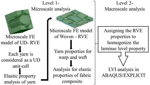
Table 2. Laminae property used for macroscale analysis (Andrews Zachariah et al., Citation2021).
3.1. Level 1 – microscale representative volume element modelling
The RVE is the tiniest volume element with an exact statistical representation of the material properties applied in a macroscale model. The RVE approach supports simulating the behaviour of material systems that contain a microstructure or distinct constituents. The RVE unit-cell model was performed using the material design modeller in ANSYS-WORKBENCH. Fibre properties and matrix properties were determined based on the manufacturer datasheet as shown in . The microscale RVE of UD unit-cell was created, and the elastic properties were determined. The properties obtained for the unit-cell has been given as the fibre strand properties in the weft and warp direction during the bidirectional plain-weaved RVE unit cell (Andrews Zachariah et al., Citation2021). The fibre volume fraction of 0.56 is upheld in the RVE model, the same as the experiment specimen (Zachariah et al., Citation2020).
Table 1. Constituent material property for RVE model.
The elastic properties of the UD unit cell attained from the level 1 microscale finite element analysis have been considered as the yarn properties in the warp and weft direction to model the microscale unit cell of woven RVE. During the woven unit cell modelling, the fabric thickness of 0.2 mm and 0.3 mm as per the manufacturer data sheet was incorporated. The plain weaving pattern was used to match the experimental sample with a reinforcement volume fraction of 0.56. An appropriate yarn spacing and 0/90 angle for the warp and weft direction was assigned to match the fibre architecture used in the experimental study.
3.2. Level 2 – the macroscale model of laminates
The elastic properties of woven RVE determined in level 1 were used as the homogenised laminae property. The basic elastic laminae properties used for the impact analysis are furnished in . The individual lamina corresponding to 0/90 and ± 45 degree orientation of carbon and aramid layers was designed using composite layup extension in the property module of ABAQUS. The laminate was dimensioned to 80 × 10 mm as per standard dimension in the experimental study. The lamina thickness was 0.27 and 0.25 mm for aramid and carbon laminate, respectively, obtained through Level 1 microscale analysis as reported in the experiment (Andrews Zachariah et al., Citation2021).
Hashin damage criteria determined the damage behaviour at the individual laminate in this study. Hashin criterion is well known for predicting failure initiation established in terms of material strengths. The four primary modes of damages in laminates at the ply level forecasted using Hashin criterion are given as follows:
Fibre tensile failure ()
(2)
(2)
Fibre compression failure ()
(3)
(3)
Matrix tensile failure ()
(4)
(4)
Matrix compression failure ()
(5)
(5)
In the equations as mentioned above, and
denotes the tensile and compressive strengths in fibre direction;
and
the tensile and compressive strengths in the transverse direction;
and
are the shear strength, respectively;
is the shear failure coefficient to determine the contribution of shear stresses on the fibre tensile failure. The evaluation of damage is influenced by the laminae fracture energy dissipated during the damage progress. The damage stabilisation viscosity coefficient in longitudinal and transverse directions is considered as 10−3 to avoid the termination of the solution, due to excessive element distortion in the respective loading directions.
3.3. Finite element modelling of Charpy impact
Numerical model for the energy absorbed during the Charpy impact test and the analysis of impact strength was developed in ABAQUS CAE (Dassault Systems SIMULIA Established Products 2023, Vélizy-Villacoublay, France). The system configuration was with processor Intel(R) Xeon(R) CPU E3-1225 v3 @ 3.20 GHz having 32.0 GB installed Ram and Nvidia Quadro K2000 2GB GPU. A macroscale approach, as illustrated in , was followed in the modelling of laminate. The solid section with a thickness equivalent to the laminate and section applied for each layer with respective lamina thickness was used for the macroscale laminate model of different specimens tested. The laminates were made of shell elements. As part of confirming the computational efficiency and accuracy, finer mesh element size of 0.25 mm derived through mesh convergence study is applied at the laminates. The overall aspect ratio of the mesh was maintained to 1 as part of maintaining the mesh quality. The total number of nodes and hexahedral elements in each sample are listed in .
Figure 3. The macroscale laminate assembly.
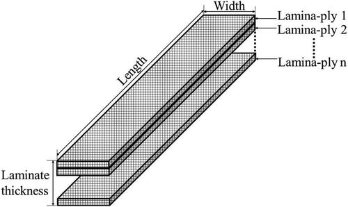
Table 3. The experimental and numerical Charpy results compared (Zachariah et al., Citation2020).
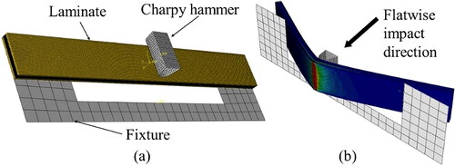
The Charpy test fixture was modelled as per ISO-179-1. The Charpy hammer head was designed as a discrete shell with a 12 mm nose radius and 30° inclination. The fixture support was created using the discrete planar shell. The Charpy setup is assembled as illustrated in .
Figure 4. The numerical macroscale laminate assembly (a) Before impact; (b) Post-impact.
3.4. Contact definition and boundary condition
The interaction properties were defined for Charpy hammer – laminate and laminate – a fixture in the FEM. General surface-to-surface contact inbuilt in ABAQUS/Explicit is used to define the contact behaviour of laminate – hammer and laminate – fixture. The tangential behaviour with penalty contact algorithm and friction coefficient of 0.7 with ‘hard normal’ contact behaviour was established (Khun et al., Citation2014; Bajpai et al., Citation2020). The impactor hits the laminate surface at the centre with a velocity and kinetic energy similar to the experimental data. The amplitude corresponding to the impact event duration was provided based on the normalised velocity against the time interval. The laminate was not constrained to exactly replicate the experimental setup. The impact duration was kept at 30 ms for all the samples with impactor velocity and mass 3.08 m/s and 1.035 kg, respectively, to produce the incident energy of 7.5 J to replicate the experimental parameters. The amplitude corresponding to the impact event duration was provided based on the normalised velocity against the time interval data.
4. Results and discussion
The low-velocity Charpy impact tests were done to examine the effect of aramid layers on impact strength and energy absorbed by hybrid carbon/aramid composites. A portion of the initial impact energy is consumed through elastic deformation (deflection) of the specimen during an impact. The different damage processes absorb the remaining energy, mainly via fiber breakage, fiber–matrix debonding, delamination and matrix cracking. The measure of the absorbed energy during an impact denotes the severity and extent of the total damage footprint. The laminate with more impact strength is better resistant towards dynamic loads in the thickness direction with enhanced energy absorption capability before undergoing a catastrophic failure. The experimental data used for comparison in this numerical study was performed as per standard recommendations in ISO179-1 (International Organization for Standardization, 2000; Zachariah et al., Citation2020).
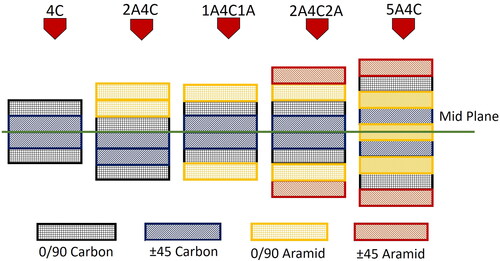
The Charpy impact test results can only be used as comparative data to assess the impact energy absorption of different materials, although standard exempts it for design purposes. Five different laminate configurations similar to the experimental study have been numerically simulated, as illustrated in .
Figure 5. The stacking details of the laminates studied in the study.
4.1. Energy-time response and impact strength
The two significant parameters obtained for the non-instrumented Charpy impact test are the energy absorbed and the corresponding impact strength. In this section, a comparison is made between the experimental data obtained concerning the absorbed energy with the numerical results. The energy-time response predicted through the numerical simulation is shown in . The absorbed energy values obtained were used to calculate the impact strength from the numerical approach. The closeness of the experimental and numerical results is illustrated in .
Figure 6. (a) The absorbed energy-time response of the tested samples; (b) The trend comparison of the impact strength between experiment and numerical data.
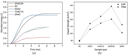
The numerical and experimental data are furnished in to compare the numerical study’s accuracy. The factors like undulations, resin-rich areas, voids and error during the tests are responsible for the overall error percentage seen among the numerical and experimental results. The efficacy of the in-built progressive damage analysis (PDA) of ABAQUS used to determine the damage evolution criteria is also evolution law may be the reason for such a variation. User-defined VUMATS developed for addressing the failure laws in the laminate can mitigate the large variation (Barbero & Barbero, Citation2019; Rogani et al., Citation2021).
4.2. Correlation of force-time response with damage morphology
The variation of force value during the contact time between the impactor and target is worthy data for analysing the damage pattern for impact studies. The factors influencing impact damage in polymer composites include the strength and stiffness of the fabric, matrix toughness, layup sequence, fiber architecture, laminate thickness, impact velocity, specimen integrity, impactor geometry and boundary support conditions. In Charpy experimental methodology, the specimen undergoing impact is not constrained; instead, a usual frictional penalty is applied between the sample and fixture (Hufenbach et al., Citation2008). The interpretation of the force-time is made based on the general impact force relation shown in EquationEquation (6)(6)
(6) :
(6)
(6)
In the above equation, impact force denoted by is directionally proportional to the impact energy
and inversely proportional to the deformation or bending
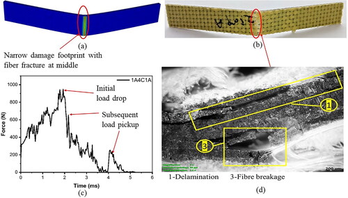
in millimeter undergone by the specimen within the stiffness limit. The major damages observed in the microscopic images are delamination, matrix crack and fibre breakage denoted by the numbers 1–3, respectively, in the respective images. Based on the above calculation, it is observed from that the 4 C sample has recorded the maximum peak force compared to the samples with aramid. Carbon laminate, known for its excellent stiffness, has resisted the impactor before undergoing a brittle fracture producing the least deflection in the force direction.
Figure 7. Correlation between numerical force-time response to damage morphology of 4 C (a) Numerical post-impact image; (b) experimental post-impact image; (c) FEM force-time plot; (d) Microscopic image of damage (Zachariah et al., Citation2020).
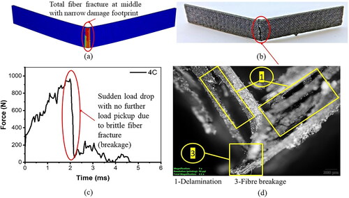
However, the sudden and brittle fracture observed in that total fibre fracture throughout the layers has caused a sudden load drop without a significant pickup of load. The brittle fracture has produced a small damage footprint near the fracture point in 4 C. The FEM image shown in exhibits the portion with the maximum red intensity as the fibre failure due to tension at the bottom surface. The FEM image for the 4 C sample also shows a very narrow damage footprint. The microscopic image of the 4 C at the fracture area is shown in .
The damage morphology of the 4 C sample consists of brittle fracture at all the layers and is shown in . The sudden load drop and the lack of further load pickup are observed due to this abrupt brittle fracture. The subsequent delamination and layer breakage have reduced the growth of delamination at the ply layers causing the narrowing of damage footprint. Such a simultaneous fibre layer fracture has reduced the vigorous sawtooth in the force-time plot. The hybrid samples 2A4C and 1A4C1A with two layers of aramid fabric exhibited a small deviation in the force-time response. The hybrid samples 2A4C and 1A4C1A with two layers of aramid fabric exhibited a minor deviation in the force-time response.
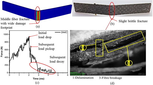
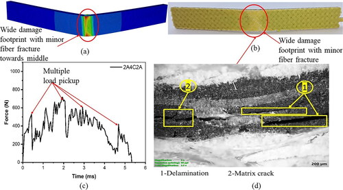
The hybrid samples 2A4C and 1A4C1A with two layers of aramid fabric exhibited a minor deviation in the force-time response. The force-time variation of 2A4C with aramid layer only at the impact side is shown in . A subsequent load pickup observed after a sudden drop due to the fracture of the carbon layer is due to the presence of an aramid layer. As the impact time progresses, the load value decays due to the total fracture of the carbon layer at the tension side. The fracture at the non-impacted surface is less severe than 4 C, as shown in . However, the damage footprint in the 2A4C is larger due to the plastic extension of the aramid layer. The damage morphology observed in consists of delamination and layer fracture in the carbon layers. However, the absence of total breakage of the carbon layer increased the delamination growth owing to more sawtooth variation in load. The widening of the damage footprint is captured in the FEM image shown in .
Figure 8. Correlation between numerical force-time response to damage morphology of 2A4C (a) Numerical post-impact image; (b) experimental post-impact image; (c) FEM force-time plot; (d) Microscopic image of damage (Zachariah et al., Citation2020).
In 1A4C1A, subsequent load drop until the end of contact duration is observed in . An aramid layer at both sides of the laminate has more fracture toughness to the sample. However, the toughness imparted by a single layer is insufficient to stop the narrow line fibre breakage due to the stress concentration originating from the abrupt brittle failure of the middle carbon layers, as shown in . Due to the near brittle fracture, the spread of damage footprint influenced by the aramid layer is less compared to 2A4C, as shown in . The damage morphology of the 1A4C1A sample consisted of a combination of layer breakage and delamination exclusively in the carbon layers, as shown in , which is accounted for the observation of more frequent load drops in the force plot. The layer breakage accompanied by the delamination in the carbon layers avoided the spread of damaged footprint. The FEM image shown in has also exhibited the same trend of narrow damage footprint with a narrow line of fibre breakage that is in line with the experimental observation.
Figure 9. Correlation between numerical force-time response to damage morphology of 1A4C1A (a) Numerical post-impact image; (b) experimental post-impact image; (c) FEM force-time plot; (d) Microscopic image of damage (Zachariah et al., Citation2020).
The increase in the aramid layer significantly reduced the peak force due to the increase in deflection of the laminate within the contact duration under load. However, the severity of sudden load drops has reduced significantly along with multiple load pickups. The presence of two layers of aramid at both sides of the laminate is the reason that prevented the single load drop, however, providing a stable plateau region resulting from the multiple peaks as shown in . The higher energy absorption observed in the 2A4C2A is the result of improved impact toughness. The damage footprint observed at the non-impact side in shows a concave profile towards the middle. This concave profile with fibre fracture away from the middle is caused by the stress concentration by ±45 sequence of aramid fabric layers. The FEM image shown in has efficiently resembled the fibre damage in concave profile with a wide damage footprint.
Figure 10. Correlation between numerical force-time response to damage morphology of 2A4C2A (a) Numerical post-impact image; (b) experimental post-impact image; (c) FEM force-time plot; (d) Microscopic image of damage (Zachariah et al., Citation2020).
The damage morphology of the 2A4C2A sample, as shown in , primarily consisted of delamination. The considerable saw tooth variation observed in the force-time plot is caused due to this delamination. The absence of fibre breakage has widened the delamination growth, causing a widened damage footprint in 2A4C2A.
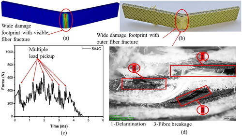
The visible fibre fracture away from the middle of the sample in the vertical direction was more in 5A4C, having alternate aramid layers. Despite having the most aramid layers, the load drop spikes were many in the case of 5A4C, as shown in . The subsequent failure of the alternate carbon layer and the sudden redistribution of the load onto the aramid layers have caused the spiky nature of the force-time response. The damage morphology of 5A4C is shown in , with more fibre breakage at intermediate in the carbon layers and kinking of the alternate aramid layer. The delamination associated with 5A4C is more due to the increase in the number of ±45 oriented layer intersections. The toughness provided by a single layer to handle the force drop from each carbon layer caused a visible fibre fracture at the non-impacted side compared to 2A4C2A, as shown in . The FEM image shown in resembles the wide damage footprint 11(b). However, these random ply failures made the energy absorption in 5A4C comparatively less compared to 2A4C2A. Even the impact strength exhibited by the 5A4C compared to 1A4C1A and 2A4C2A with each layer of aramid at both the sides. Thus, it can be inferred that apart from the number of tougher layers in hybrid composite, the location and layup sequence account for the total impact performance.
Figure 11. Correlation between numerical force-time response to damage morphology of 5A4C (a) Numerical post-impact image; (b) experimental post-impact image; (c) FEM force-time plot; (d) Microscopic image of damage (Zachariah et al., Citation2020).
5. Conclusion
In this article, validation of the numerical Charpy model against the experimental data has been performed. The material properties for the macroscale numerical model of the hybrid carbon/aramid laminates were developed based on microscale RVE homogenisation. The macroscale analysis was carried out in ABAQUS/EXPLICIT with the parameters and boundary conditions similar to the experimental study (Zachariah et al., Citation2020). The major contribution of the study is as follows:
The macroscale model discussed has closely predicted the amount of energy absorbed and impact strength reported in the experimental data with less than 10% error. The numerical values are higher than the experimental data. The key reasons for such differences are the minor imperfections in fabricated laminates and the errors due to the mechanical losses from testing equipment. The effectiveness of the PDA approach can also create variations in the instantaneous stress-strain values, producing deviations in the overall predictions.
The output data from the non-instrumented Charpy test was limited to the energy absorbed values. The damage observed in the experimental study was not coupled with a force-time response in understanding the behaviour of the laminate towards impact force. However, the force-time response predicted using the current modelling strategy good provide better insight into the damage propagation. The analysis of the force-time variation from the contact time was influential in concluding the reason for the low value of energy absorption and impact strength in 5A4C laminate compared to other samples despite having the maximum number of tougher aramid layers.
The force drop variation extracted from the numerical simulation was in fair correlation to the damage morphology observed in the microscopic images of the post-impact samples reported by the author in the earlier work. The force-time data from the numerical data can provide better insight into the damage propagation and resulting damage morphology that can enhance the understandability and credibility of the non-instrumented LVI Charpy test whereby surpassing its limitations.
This study anticipates giving valuable contributions to investigate further the hybrid composite’s property improvement with different fibre architectures. Despite the need for extensive computational competencies and more time consuming, future FEM studies in the damage behaviours of composite materials based on modified user-defined material (UMAT) subroutine at microscale and macroscale levels can predict the various damage behaviours of composite materials under various loading conditions with improved accuracy.
Author contribution
1. Sojan Andrews Zachariah (first author) – Conception, Methodology, Software, Validation, Formal analysis, Investigation, Data Curation, Writing – original draft, Visualisation.
2. Pai Dayananda (first author) – Conception, Methodology, Investigation, Data Curation, Formal analysis, Resources, Writing – Review & Editing of original manuscript, Supervision.
3. Padmaraj N H – Experimental Validation, Formal analysis, Data Curation, Visualisation.
4. Satish Shenoy B (Corresponding author) – Conception, Resources, Writing, Review and Editing manuscript, Supervision, Project administration, Correspondence with the journal.
Acknowledgements
The authors would like to acknowledge facility support from the Department of Aeronautical and Automobile Engineering, Manipal Institute of Technology (MIT), MAHE, Manipal.
Disclosure statement
The authors declare that they have no known competing financial interests or personal relationships that could have appeared to influence the work reported in this article.
Data availability statement
The data that support the findings of this study are available from the corresponding author, [B.S.S.], upon reasonable request.
Additional information
Funding
Notes on contributors
Sojan Andrews Zachariah
Dr. Sojan Andrews Zachariah earned his Doctorate degree from the Manipal Academy of Higher Education. He is currently employed in the Department of Operations and Development at Worldwide Oilfield Machine Middle East in Dubai, United Arab Emirates. His research interests include composite materials and finite element modeling (FEM).
Pai K. Dayananda
Dr. Dayananda K. Pai serves as a Professor and the Head of the Department of Aeronautical & Automobile Engineering at the Manipal Institute of Technology, part of the Manipal Academy of Higher Education in Manipal. He earned his Ph.D. in Mechanical Engineering from the National Institute of Technology Karnataka. His research interests include composite materials, manufacturing, design, and optimization.
Padmaraj N. H.
Dr. Padmaraj N. H. is an Associate Professor in the Department of Aeronautical & Automobile Engineering at the Manipal Institute of Technology, Manipal Academy of Higher Education, Manipal. He earned his Ph.D. from the Manipal Academy of Higher Education. His research interests include natural fiber reinforced composites, vehicle aerodynamics, fatigue analysis, and advanced materials.
Satish Shenoy B.
Dr. Satish Shenoy B. holds a Ph.D. in Tribology from the Manipal Academy of Higher Education. He is currently a Professor in the Department of Aeronautical and Automobile Engineering at the Manipal Institute of Technology, part of the Manipal Academy of Higher Education, Manipal. His research interests include composite materials, 3D printing, computational fluid dynamics, fluid film lubrication, and fluid-structure interaction in bearings and seals.
References
- Andrews Zachariah, S., & Satish Shenoy, D. P. (2021). Experimental analysis of the effect of the woven aramid fabric on the strain to failure behaviour of plain weaved carbon/aramid hybrid laminates. Facta Universitatis, series: Mechanical engineering (pp. 1–13). https://doi.org/10.22190/FUME200819022Z.
- Andrews Zachariah, S., Satish Shenoy, B., & Dayananda Pai, K. (2021). Comprehensive analysis of in-plane tensile characteristics of thin carbon/aramid hybrid composites using experimental and RVE-based numerical study. Composite Structures, 271, 114160. https://doi.org/10.1016/j.compstruct.2021.114160
- Bajpai, A., Saxena, P., & Kunze, K. (2020). Tribo-mechanical characterization of carbon fiber-reinforced cyanate ester resins modified with fillers. Polymers, 12(8), 1725. https://doi.org/10.3390/POLYM12081725
- Barbero, E. J., & Barbero, J. C. (2019). Determination of material properties for progressive damage analysis of carbon/epoxy laminates. Mechanics of Advanced Materials and Structures, 26(11), 938–947. https://doi.org/10.1080/15376494.2018.1430281
- Caminero, M. A., Rodríguez, G. P., & Muñoz, V. (2016). Effect of stacking sequence on Charpy impact and flexural damage behavior of composite laminates. Composite Structures, 136, 345–357. https://doi.org/10.1016/j.compstruct.2015.10.019
- Denning, K. (2004). Design, construction, and testing of a high-speed light weighted UAV. Collect [Paper presentation]. Technical Paper - AIAA 3rd "Unmanned Unlimited" Technical Conference, Workshop and Exhibit (Vol. 2, pp. 1128–11–37). 20–23 September 2004, Chicago, Illinois. https://doi.org/10.2514/6.2004-6614
- Dixit, A., Mali, H. S., & Misra, R. K. (2013). Unit cell model of woven fabric textile composite for multiscale analysis. Procedia Engineering, 68, 352–358. https://doi.org/10.1016/j.proeng.2013.12.191
- Dong, Z., & Sun, C. T. (2009). Testing and modeling of yarn pull-out in plain woven Kevlar fabrics. Composites Part A: Applied Science and Manufacturing, 40(12), 1863–1869. https://doi.org/10.1016/j.compositesa.2009.04.019
- Erkliğ, A., & Bulut, M. (2017). Experimental investigation on tensile and Charpy impact behavior of Kevlar/S-glass/epoxy hybrid composite laminates. Journal of Polymer Engineering, 37(2), 177–184. https://doi.org/10.1515/polyeng-2015-0538
- Fotouhi, M., Jalalvand, M., & Wisnom, M. R. (2017). High performance quasi-isotropic thin-ply carbon/glass hybrid composites with pseudo-ductile behaviour in all fibre orientations. Composites Science and Technology, 152, 101–110. https://doi.org/10.1016/j.compscitech.2017.08.024
- Hufenbach, W., Ibraim, F. M., Langkamp, A., Böhm, R., & Hornig, A. (2008). Charpy impact tests on composite structures - An experimental and numerical investigation. Composites Science and Technology, 68, 2391–2400. https://doi.org/10.1016/j.compscitech.2007.10.008
- International Organization for Standardization. (2000). Plastics—determination of Charpy impact properties, part 1: Non-instrumented impact test. International Organization for Standardization.
- Khun, N. W., Zhang, H., Lim, L. H., Yue, C. Y., Hu, X., & Yang, J. (2014). Tribological properties of short carbon fibers reinforced epoxy composites. Friction, 2(3), 226–239. https://doi.org/10.1007/s40544-014-0043-5
- Kosedag, E., & Ekici, R. (2022). Low-velocity and ballistic impact resistances of particle reinforced metal–matrix composites: An experimental study. Journal of Composite Materials, 56(7), 991–1002. https://doi.org/10.1177/00219983211068101
- Liu, H., Shi, W., Gao, R., Chen, Z., & Chen, H. (2021). Stiffness prediction and analysis of composite leaf springs. IEEE Access, 9, 54888–54899. https://doi.org/10.1109/ACCESS.2021.3070440
- Marszałek, J., Stadnicki, J., & Danielczyk, P. (2020). Finite element model of laminate construction element with multi-phase microstructure. Science and Engineering of Composite Materials, 27(1), 405–414. https://doi.org/10.1515/secm-2020-0044
- Metin, F., & Avcı, A. (2021). In-plane quasi-static and out-of-plane dynamic behavior of nanofiber interleaved glass/epoxy composites and finite element simulation. Composite Structures, 270, 114085. https://doi.org/10.1016/j.compstruct.2021.114085
- Naghdinasab, M., Farrokhabadi, A., & Madadi, H. (2018). A numerical method to evaluate the material properties degradation in composite RVEs due to fiber-matrix debonding and induced matrix cracking. Finite Elements in Analysis and Design, 146, 84–95. https://doi.org/10.1016/j.finel.2018.04.008
- Naik, N. K., Chandra Sekher, Y., & Meduri, S. (2000). Damage in woven-fabric composites subjected to low-velocity impact. Composites Science and Technology, 60(5), 731–744. https://doi.org/10.1016/S0266-3538(99)00183-9
- Papakaliatakis, G., & Karalekas, D. (2010). Damage growth by debonding in a single fibre metal matrix composite: Elastoplasticity and strain energy density criterion. Theoretical and Applied Fracture Mechanics, 53(2), 152–157. https://doi.org/10.1016/j.tafmec.2010.03.005
- Pascal, F., Dorival, O., Navarro, P., Marguet, S., & Ferrero, J. F. (2018). Impact damage prediction in thin woven composite laminates – Part I: Modeling strategy and validation. Composite Structures, 190, 32–42. https://doi.org/10.1016/j.compstruct.2018.02.007
- Ramesh, P. S., & Lal, M. (2020). Mini unmanned aerial systems (UAV)-A review of the parameters for classification of a mini UAV. International Journal of Aviation, Aeronautics, and Aerospace, 7, 5. https://doi.org/10.15394/ijaaa.2020.1503
- Rawat, P., Singh, K. K., & Singh, N. K. (2017). Numerical investigation of damage area due to different shape of impactors at low velocity impact of GFRP laminate. Materials Today: Proceedings, 4(8), 8731–8738. https://doi.org/10.1016/j.matpr.2017.07.222
- Rayhan, S. B., & Rahman, M. M. (2020). Modeling elastic properties of unidirectional composite materials using ansys material designer. Procedia Structural Integrity, 28, 1892–1900. https://doi.org/10.1016/j.prostr.2020.11.012
- Rogani, A., Navarro, P., Marguet, S., Ferrero, J. F., & Lanouette, C. (2021). Study of post-impact behaviour of thin hybrid carbon/epoxy and glass/epoxy woven composite laminates under fatigue tensile loading – Part II: Numerical study. Composite Structures, 260, 113451. https://doi.org/10.1016/j.compstruct.2020.113451
- Shah, S. Z. H., Karuppanan, S., Megat-Yusoff, P. S. M., & Sajid, Z. (2019). Impact resistance and damage tolerance of fiber reinforced composites: A review. Composite Structures, 217, 100–121. https://doi.org/10.1016/j.compstruct.2019.03.021
- Shi, Y., Swait, T., & Soutis, C. (2012). Modelling damage evolution in composite laminates subjected to low velocity impact. Composite Structures, 94(9), 2902–2913. https://doi.org/10.1016/j.compstruct.2012.03.039
- Siddiqui, M. O. R., & Sun, D. (2017). Development of plug-ins to predict effective thermal conductivity of woven and microencapsulated phase change composite. Journal of Composite Materials, 51(6), 733–743. https://doi.org/10.1177/0021998316655202
- Sørensen, B. F. (2017). Micromechanical model of the single fiber fragmentation test. Mechanics of Materials, 104, 38–48. https://doi.org/10.1016/j.mechmat.2016.10.002
- Swolfs, Y., Gorbatikh, L., & Verpoest, I. (2014). Fibre hybridisation in polymer composites: A review. Composites Part A: Applied Science and Manufacturing, 67, 181–200. https://doi.org/10.1016/j.compositesa.2014.08.027
- Yeshwant Nayak, S., Rajath Shenoy, K., Satish Shenoy, B., & Sultan, M. T. H. (2021). Numerical approach to evaluate failure of composites under ballistic impact suhas. Impact studies of composite materials (pp. 161–184). Springer
- Zachariah, S. A., Dayananda Pai, K., & Satish Shenoy, B. (2021). Multi-level hybridization in mitigating impact damages in advanced composites – A review on recent trends. Materials Today: Proceedings, 46, 9059–9066. https://doi.org/10.1016/j.matpr.2021.05.388
- Zachariah, S. A., Shenoy, B. S., Jayan, J., & Pai, K. D. (2020). Experimental investigation on dynamic and static transverse behavior of thin woven Carbon/Aramid hybrid laminates. Journal of King Saud University - Engineering Sciences, 34, 273–281. https://doi.org/10.1016/j.jksues.2020.09.015