
 ?Mathematical formulae have been encoded as MathML and are displayed in this HTML version using MathJax in order to improve their display. Uncheck the box to turn MathJax off. This feature requires Javascript. Click on a formula to zoom.
Abstract
Hand-pushed cone penetrometer has been utilized to assess soil compaction based on soil penetration resistance (SPR). However, the manual operation of these devices can be quite challenging and erroneous. The accuracy of the data gathered using such devices can be hindered by the operator’s limitation in maintaining a constant-rate of penetration into the soil, thus preventing the attainment of a steady, predefined penetration rate. To address this issue, a constant-rate, IoT-enabled cone penetrometer is designed and constructed. The developed penetrometer measures the SPR across the soil profile with a designed lead screw arrangement that ensures a constant-rate penetration. The device comprises a mechanical system and an electronic control unit that utilizes IoT framework. The mechanical system includes a primary frame, lead screw arrangement and a standard penetrometer probe. The SPR, and depth along with coordinates of location are measured and stored on a web server. A user-friendly customizable web interface and mobile application enable real-time access. The developed penetrometer measures the SPR up to 2000 kPa up to 400 mm depth. Comparative analysis shows that the constant-rate penetrometer (CRP) provides more reliable and less variable resistance measurements compared to the hand-pushed penetrometer (HPP), with significant differences observed at multiple depths. This penetrometer maintains a constant-rate of penetration, ensuring adherence to predefined standards for accurate measurements.
1. Introduction
Amidst multitude of global challenges, the agricultural sector plays a pivotal role in addressing issues related to food security, environmental sustainability and efficient use of resources (Karunathilake et al., Citation2023; Serraj et al., Citation2019). As the global population continues to grow, demand for increased agricultural productivity has become increasingly pressing. Meeting this demand necessitates the integration of cutting-edge technology into modern agriculture to optimize farming practices and resource management.
Soil health is a critical factor that exerts a profound influence on agricultural productivity and crop growth. The intrinsic properties of soil, encompassing factors such as compaction, moisture content and nutrient availability, play a pivotal role in determining both the quantitative yield and qualitative characteristics of crop cultivation (Kibblewhite et al., Citation2008; Shah et al., Citation2017). Among these soil characteristics, soil compaction, often measured through soil penetration resistance (SPR) (commonly referred to as the soil cone index), is a crucial parameter that affects root penetration, water infiltration and nutrient uptake and hinders plant root growth (Al-Sammarraie & Kırılmaz, Citation2023; Bengough et al., Citation2000; Moraes et al., Citation2014). The measurement of the SPR is facilitated by a device commonly known as a cone penetrometer.
In agricultural applications, cone penetrometer is extensively employed to assess hindrances to root growth and crop establishment (Capobiango et al., Citation2022; Mosaddeghi et al., Citation2009), soil compaction (Canillas & Salokhe, Citation2002; Veronesi et al., Citation2012), soil trafficability (Eichrodt, Citation2003) and the effectiveness of tillage operations (Castrignanò at el. Citation2003). Additionally, the penetrometer has become an essential part of tillage operations, offering insights into soil strength both before and after tillage experiments (Farzaneh et al., Citation2012; Patidar et al., Citation2024). Accurate and timely measurement of the cone index is essential for informed decision-making in precision agriculture, allowing farmers to gauge soil compaction levels and implement corrective measures to optimize crop growth.
The basic specifications for the penetrometer are outlined in ASABE Standard S313.3 (ASABE Standards, Citation2006a). In brief, the standard specifies a cone with an enclosed angle of 30° and attached to a polished shaft. There are two specified variants of cone bases: one with a cone diameter of 20.27 mm and a shaft diameter of 15.88 mm, resulting in a base area of 323 mm2, suitable for soft soils with SPR up to 2 MPa. The other variant has a cone diameter of 12.83 mm and a shaft diameter of 9.53 mm, resulting in a base area of 130 mm2, suitable for hard soils with SPR values up to 5 MPa. The cone and shaft are inserted into the soil at a fixed velocity of 30 mm/s (ASABE Standards, Citation2006b).
Based on these specifications, previous researchers (Anderson et al., Citation1980; Ani & Mbajiorgu, Citation2009; Balkcom et al., Citation2016; Chi & Tessier, Citation1995; Fountas et al., Citation2013; Naderi-Boldaji et al. Citation2009; Olsen, Citation1990; Reiffsteck et al., Citation2009; Rezaee, Citation2017; Schmittmann & Lammers, Citation2023) had designed and developed various configurations of cone penetrometers equipped with strain-gauged transducers (load cell) to measure penetration force and data logger as an acquisition system for data recording. These penetrometers incorporate different sensors for penetration depth measurements, including ultrasonic sensors, infrared sensors, optical sensors and rotary potentiometers, necessitating regular calibration prior to usage. Moreover, the manual operation of these penetrometers presents practical challenges, resulting in an inconsistent rate of penetration into the soil, which deviates from the standard (ASABE Standards, Citation2006b). Furthermore, these devices offer limited accessibility to real-time data, constraining the ability of farmers to make on-the-spot decisions regarding soil management.
Given the inherent difficulties in achieving a consistent penetration rate with manually operated cone penetrometers, several researchers have endeavored to design and develop tractor-mounted, hydraulically driven penetrometers (Alimardani, Citation2005; Boon et al., Citation2005; Nisha et al., Citation2023; Thiyagarajan et al., Citation2013). Although numerous tractor-mounted units comply with ASABE standards, their applicability is limited to low-lying row crops, making them less suitable for comprehensive soil compaction research due to the impact of wheel traffic. Additionally, they are not practical in wooded areas or soft soil regions where the tractor’s accessibility is limited.
Internet of Things (IoT) technology integration in recent years has ushered in a new era of agricultural mechanization. The IoT enables autonomous systems that utilize machine learning and artificial intelligence to process real-time data and can be acted on to adjust routes or make decisions related to mobility (traction control) (Ahmad & Nabi Citation2021; Mahore et al., Citation2024; Sivakumar et al., Citation2022). IoT facilitates the seamless integration of sensors and data transmission devices into agricultural equipment and leads in enabling data-driven decision support systems (Huo et al., Citation2024; Mahore et al., Citation2023; Saha et al., Citation2021). This technological advancement presents a unique opportunity to modernize soil compaction measurements, offering real-time and data-rich solutions.
This study focused on the development and compilation of a portable, constant-rate, IoT-enabled cone penetrometer to ensure constant-rate penetration for measuring SPR. This innovative device aims to overcome the limitations associated with traditional penetrometers and offers a versatile tool for efficient and effective soil compaction measurements for both farmers and researchers. By merging IoT capabilities with constant-rate penetration, this inventive device promises real-time data collection, empowering timely decisions to optimize soil management practices.
2. Materials and methods
2.1. Overall architecture of IoT-enabled cone penetrometer
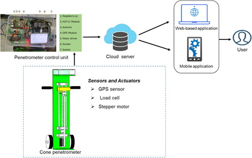
The developed IoT-enabled cone penetrometer comprises both hardware and software that utilize IoT-based technology. shows the overall architecture of the IoT-enabled cone-penetrometer. The hardware component comprises a standard penetrometer rod and cone, raspberry-pi, load cell, GPS module and stepper motor. The software component includes a server incorporating a created web service that serves as a data logger and a cloud-based analytic system. The software component is also equipped with a custom web-based application and a mobile application interface that supports the real-time monitoring of measured data.
Figure 1. Overall architecture of the IoT-enabled based cone penetrometer.
2.2. Mechanical design and implementation
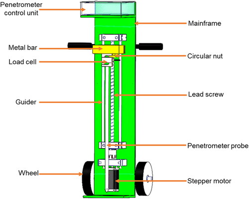
The computer-aided design (CAD) model of the developed cone penetrometer is depicted in the drawing (). The developed penetrometer comprised three primary components: 1) a driving mechanism for pushing the penetrometer probe into the soil at the set standard speed, 2) a sensor unit for measuring the force required to push the probe into soil and 3) a penetrometer control unit. The driving system of the penetrometer was facilitated by a stepper motor using a screw lead mechanism to control the vertical movement of penetrometer probe. This configuration enables the attainment of a specified constant-rate penetration of 30 mm/s in accordance with the standard fixed by the American Society of Agricultural and Biological Engineers (ASABE Standards, Citation2006b). The study included a penetrometer probe that conformed to the specifications outlined in the ASABE standards. The probe included a cone with a base diameter of 20.30 mm, a shaft diameter of 15.90 mm, a cone base area of 323 mm2 and an apex angle of 30° (ASABE Standards, Citation2006a).
Figure 2. CAD model of the constant-rate, IoT-enabled cone penetrometer.
Based on the Indian Standard (IS: 4218 (Part III), Citation1976) and considering the availability, a lead screw having a square thread on its outer surface, with a pitch of 12.70 mm, and a selected outer diameter of 32 mm was chosen. The round nut is affixed onto a screw with an inner diameter of 32 mm and a length of 60 mm. Stroke length for the lead screw was selected based on the requirement of achieving a maximum penetration depth suitable for conducting compaction studies in deep soil profile layers. A stroke length of 400 mm was determined to be appropriate for this purpose.
Determination of appropriate size for a stepper motor is dependent upon various criteria, in addition to the intended use. The load (F) applied to the lead screw via the penetration probe and that transmitted to the stepper motor was determined using EquationEquation (1)(1)
(1) . The proposed penetrometer was designed to accommodate a maximum SPR of 2000 kPa.
(1)
(1)
where F is load (N), P is maximum SPR (Pa) and A is area of the penetrometer cone base (m2).
The minimal torque (T) required to sustain the necessary insertion pressure of the probe into the soil was determined using EquationEquation (2)(2)
(2) as described by Patel et al. (Citation2013). This equation establishes a relationship between the applied force and the torque necessary within a mechanical system, incorporating considerations for the factor of safety and system efficiency.
(2)
(2)
where T represents the torque (Nm), F is the load applied (N), p is the pitch (m), FS is a factor of safety (considered as 3) and η is the efficiency of a lead screw system (taken as 45%).
Based on the calculated requirement and as per availability, 10 Nm torque, stepper motor (Nema 34, Rhino Motion Controls, India) was chosen for vertical movement of penetrometer probe transmitted via lead screw arrangement with maintaining the constant-rate penetration. The developed penetrometer included the sensing unit consisted of an S-type load cell of 200 kg capacity fitted between the threaded end of the metal bar and cone penetrometer rod to measure the penetration resistance force.
2.3. Electronic control design and implementation
illustrates the entire schematic circuit design of the electronic control unit employed in the development of IoT-enabled cone penetrometer. The electronic control unit comprised several components: Raspberry Pi, Arduino microcontroller, stepper motor, motor driver, load cell sensor and GPS module. All the electronic components were powered with a power supply battery of 24 volt. The specifications of the electronic components used in the cone penetrometer are presented in .
Figure 3. Circuit diagram of electronic control unit (Software used: EasyEDA).
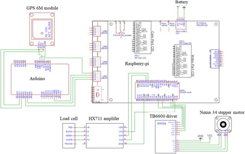
Table 1. Specifications of the electronic components used in cone penetrometer.
The stepper motor having step angle of 1.8° was powered to drive the penetrometer probe through soil via lead screw and record the penetrometer’s data through the developed control unit. To attain the targeted penetration speed of 30 mm/s, it is necessary to establish a constant pulse frequency for the stepper motor. The angular velocity (𝜔) of the motor is determined by dividing the linear speed by the pitch, as stated in EquationEquation (3)(3)
(3) :
(3)
(3)
Hence, for the required angular speed of 142 rev/min, the corresponding pulse frequency (fz) is given by EquationEquation (4)(4)
(4) :
(4)
(4)
where a is the step resolution of the motor. In this study, 800 steps for one revolution were selected in the motor driver.
Therefore, the stepper motor was provided with a consistent pulse frequency of 1894 Hz in order to achieve the intended speed of the motor and thereby maintaining the penetration rate. The raspberry-pi was programmed with the calculated pulse frequency to maintain the penetration rate of the penetrometer probe at the predefined standard.
The same stepper motor was also utilized in determining the depth of probe penetration by tracking the number of step rotations executed. The chosen pitch of the lead screw was 12.70 mm, while the desired penetration rate for the cone penetrometer is 30 mm/sec. Correspondingly, the motor’s angular speed is 2.36 rev/s, as calculated by the drive ratio of 30:12.70. As a result, within a duration of 1 s, the motor completes 2.36 revolutions. Additionally, the motor driver has been configured to execute 800 steps for each revolution. Based on the calculation, it can be determined that there are 1888 steps per second (multiplying 2.36 by 800). Thus, it can be determined that for every 1 mm, there are 62 steps, as calculated by the ratio of 1888:30. This established a relation between steps of motor and advancement of penetrometer probe, and was the basis for penetration depth measurement.
The sensing unit of the developed system consisted of an S-type load cell. The load cell was fitted between the threaded end of the metal bar attached to the circular nut moving over the screw and penetrometer rod to measure the force necessary to push the probe through the soil. The force readings obtained from the load cell were converted into SPR by dividing it by the base area of the cone, i.e. 323 mm2. A GPS module was used for positioning the cone penetrometer unit in the measurement location.
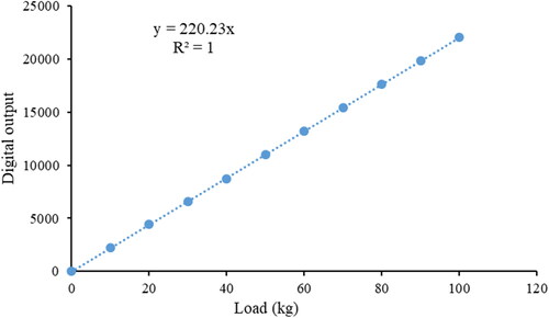
The calibration result of the load cell used in the designed penetrometer is depicted in . The presence of a strong linear connection (R2 ≈ 1) between the output voltage of the load cell and the applied force within the range of zero to 100 kg is apparent. Thus, the output voltage of the load cell serves as the reference signal to determine the penetration force.
Figure 4. Calibration curve for load cell.
A computer program was designed and compiled on the raspberry-pi. This program maintains the penetration speed, taking into account the calculated pulsed frequency, and converts the raw voltage values obtained from the load cell into SPR. In addition, the program tracked the motor’s steps to measure the depth of penetration.
2.4. Software development and implementation
A web-based application and a mobile application were developed to visualize the real-time measured data from anywhere, at any time, and by anyone. The web-based application was built using HTML, Cascading Style Sheets (CSS), and JavaScript. HTML constructs the basic structure of the webpage, while CSS is used for styling the existing page structure. JavaScript, on the other hand, adds dynamic elements to the webpage using a programming language. These tools are used to create a graphical user interface for monitoring the measured data in real-time.
The mobile application was developed using Android Studio version 3.1, which serves as a platform for creating Android applications. The code for the application was written in XML and Java and compiled using a compiler. The user interface of the developed applications was designed to display SPR, penetration depth, along with the latitude and longitude of the data capturing location.
2.5. Validation of the developed cone penetrometer in soil bin
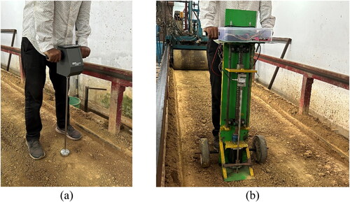
Performance of the developed constant-rate penetrometer (CRP) was assessed in a soil bin within controlled laboratory conditions. Its performance was compared with that of a standard hand-pushed penetrometer (HPP) (Daiki DIK-5532, Saitama, Japan). This experiment was done in the soil tillage laboratory of the Agricultural and Food Engineering Department, IIT Kharagpur. The soil bin used for performance evaluation is a rectangular structure with dimensions of 15.0 m length, 1.8 m width and 0.6 m depth. The soil used in the experiments was characterized as sandy clay loam. To ensure uniform compaction levels across the soil bed, a soil processing trolley was utilized, which consisted of a rotary tiller, a leveling blade, and a roller for soil tillage, leveling, and compaction, respectively, as illustrated in . This allows to prepare the soil with consistent compaction levels throughout the entire soil bed, as depicted in .
Figure 5. Soil bin (a) Soil processing trolley (i) Hydraulic system for soil bin automation; ii) Rotary tiller; iii) Levelling blade; iv) Roller) and (b) Prepared soil bed.
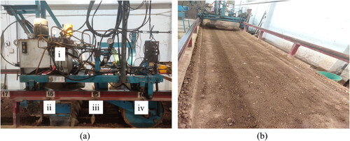
In the experimental setup, two penetrometers were employed: a HPP () and the developed CRP (). Before initiating the measurement procedure, adjustments were made to both penetrometers to ensure the utilization of a 30° cone with a base area measuring 323 mm2. In the soil bin, the measurement of SPR was performed using both penetrometers. Twenty places were chosen along a 10 m length, with each location being placed at 0.5 m intervals, to facilitate data collection using both penetrometers. Measurements with the developed CRP were made at a lateral distance of 10 cm from the points measured by the HPP. Both penetrometers were configured to collect data at intervals of 2 cm, up to a maximum depth of 24 cm.
Figure 6. Experimentation in soil bin (a) Hand-pushed penetrometer and (b) Developed constant-rate penetrometer.
3. Results and discussion
3.1. Developed IoT-enabled cone penetrometer
A portable, constant-rate, IoT-enabled cone penetrometer () was successfully developed for measuring a maximum SPR of 2000 kPa up to a penetration depth of 400 mm with penetrometer probe (cone base area 323 mm2 with a 15.90-mm diameter shaft (ASABE Standards, Citation2006a)). The major components, such as the driving system for pushing the penetrometer probe into the soil up to the appropriate depth at the desired speed, the sensor unit to measure the force required to penetrate the penetrometer probe through the soil, and the cone penetrometer control unit, were successfully developed.
Figure 7. Developed IoT-enabled cone penetrometer. (1) Mainframe; (2) Handle; (3) Penetrometer control unit; (4) Circular nut; (5) Metal bar; (6) Load cell; (7) Lead screw; (8) Guider; (9) Penetrometer probe; (10) Coupler; (11) Stepper motor; (12) Transport wheels.
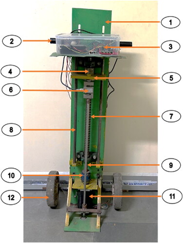
In the design penetrometer unit, the penetrometer probe was mounted on the mainframe with a lead screw arrangement driven by a high-torque stepper motor. The stepper motor was connected to the lead screw via a coupler in order to transmit motion to the screw. The round nut that is affixed to the screw and facilitates its movement along its axis. The penetrometer probe is connected to the metal bar that is fixed on round nut in order to facilitate its translational motion along the lead screw and is supported by two guiding rails. The load cell is attached in between the metal bar and penetrometer probe that facilitates the penetration. A flat panel at the base of the penetrometer unit ensures that the probe could penetrate vertically, regardless of the terrain’s irregularities. This feature proved particularly advantageous in situations involving tillage systems where the soil surface was uneven.
Moreover, the mainframe served dual purposes: it functions as a support structure for the lead screw arrangement and the penetrometer, while also serving as a transport unit due to its attachment to two wheels. By exerting downward force on the handles and shifting the unit’s weight onto the wheels, the device could be raised off the ground and easily maneuvered, even across rugged soil surfaces.
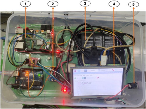
The control unit () of the penetrometer contains a raspberry-pi microprocessor, a motor driver and a GPS sensor. This unit is responsible for operating the penetrometer and recording SPR and penetration depth data along with the latitude and longitude of the measurement location. To maintain the penetrometer probe’s penetration speed at the desired level, the microprocessor is used to control the stepper motor. To measure the force required for penetration, an S-type load cell is placed between the threaded end of the metal bar and the penetrometer rod. The penetration depth of the penetrometer probe within the soil is calculated using the step count of the stepper motor. In addition to this data, the GPS sensor connected to the microprocessor records important information, such as location coordinates of the measurement. A Wi-Fi module is used to transmit the collected data from the microprocessor unit to a web server. This data is also stored on the web server, serving as a data logger. Furthermore, a customized web-based application and a mobile application have been developed to allow users to access this data in real-time from a remote location.
Figure 8. The electronic control unit. (1) Raspberry-pi; (2) GPS sensor; (3) Motor driver; (4) Screen (5) Switch.
3.2. Designed web-based and mobile application for real-time data monitoring
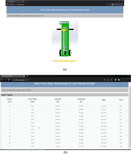
The web interface, which has been developed for the purpose of real-time monitoring of cone index data, penetration depth and corresponding geographical coordinates (latitude and longitude), can be accessed by entering the web address over the internet. Upon navigating to the designated web URL, visitors are redirected to the primary page of the web-based application, as depicted in . The main menu of the web-based interface is shown in , showcasing the data gathered from the sensor during the system’s operation. Users can generate a real-time graphical representation of the data by navigating to the ‘General Graphics’ tab. The dashboard allows users to conveniently monitor data pertaining to several criteria, with the added functionality of automatic real-time updates.
Figure 9. Web-based application for penetrometer data visualization (a) Home page and (b) Soil strength information page.
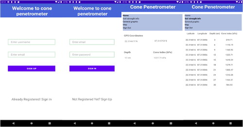
The mobile application (), based on the Android platform, was used to monitor the real-time monitoring of cone index data and penetration depth along with latitude and longitude. The application comprises three primary functions: (a) Authentication, (b) Home and (c) Soil strength information. The Authentication tab facilitates user access to the designated device database. After accessing the database, the application proceeds to retrieve the requisite data and subsequently shows it on the user interface. The Home view offers viewers the ability to monitor the functioning of the cone penetrometer in real-time. The Soil strength information view is responsible for displaying data in a tabular representation. Moreover, this application facilitates the registration process for new users by requesting the necessary information.
Figure 10. User interface of the developed mobile application.
3.3. Comparative performance between developed constant-rate penetrometer and hand-pushed penetrometer
In order to assess the performance of the designed CRP, laboratory experiments were carried out to evaluate its performance in comparison to HPP. illustrates a comparison of the average SPR readings obtained from both penetrometers at 20 different locations displayed at 20 mm depth intervals, ranging from zero to a depth of 24 cm. The measurement of SPR with the HPP consistently showed a lag compared to the constant rate device for a given penetration depth. This observed delay and the accompanying variability are attributed to operator errors, as the hand-push unit encounters difficulties in maintaining a consistent rate of penetration, as highlighted in earlier studies (Larney et al., Citation1989; Lowery, Citation1986). Additionally, maintaining the HPP in a vertical position during measurements of penetration resistance proved to be challenging. Incorrect positioning of the unit also leads to inaccurate outcomes due to the presence of friction between the penetrometer rod and the soil.
Figure 11. Comparison of (a) average cone index and (b) coefficient of variation between constant-rate penetrometer (CRP) and hand-pushed penetrometer (HPP).

The coefficient of variation (CV), as observed in , exhibited greater values for the majority of depths when using the HPP compared to the CRP. The variability of penetration profiles obtained from the constant rate penetrometer was observed to be lower compared to those obtained from the hand-pushed device when both were used to assess the same compacted soil level.
compares SPR profiles using a CRP and a HPP across various depths (2–24 cm). Variability, indicated by standard deviation (SD) and CV, is consistently lower for the CRP, suggesting more precise and consistent measurements. Significant differences (p < 0.05) in penetration resistance between the two penetrometers are observed at multiple depths, particularly at 2 cm, 10 cm, 12 cm, 14 cm, 16 cm, 20 cm, 22 cm and 24 cm, as indicated by the paired t statistics. These results imply that the CRP provides more reliable and less variable resistance measurements, while the HPP shows higher resistance values with greater variability. The differences could be attributed to the distinct operational mechanisms of the two devices, with the CRP’s controlled penetration rate likely contributing to its consistency. Thus, for precise soil resistance profiling, the CRP appears to be the more reliable device.
Table 2. Soil penetration resistance profile statistics for the constant-rate penetrometer vs. the hand-pushed penetrometer.
4. Conclusions
A portable, constant-rate, IoT-enabled cone penetrometer was successfully designed and constructed for measuring the SPR. The developed penetrometer ensures a specified constant-rate of penetration throughout the soil profile. This device consists of a mechanical unit and an electronic control unit, employing IoT. The mechanical system includes a primary frame, lead screw arrangement, and penetrometer probe. The electronic control unit consists of components, such as raspberry-pi, stepper motor, GPS sensor and S-type load cell. This unit enables the collection of real-time data from penetrometer and its remote monitoring via a customized web-based and mobile application employing an IoT framework. The developed penetrometer demonstrated the ability to assess SPR, achieving measurements of up to 2000 kPa at depth of up to 400 mm. The developed IoT-enabled cone penetrometer not only improves the accuracy of soil compaction measurements but also leads in quick data collection process – e.g. soil compaction mapping. The real-time monitoring and remote data access offer a valuable tool for researchers and progressive farmers in the field of soil compaction measurement. This study signifies a notable advancement in the pursuit of enhanced accuracy and effectiveness in the assessment of soil characteristics.
Authors’ contributions
Vijay Mahore: conceptualization, methodology, data curation, formal analysis, software, writing – original draft, writing – review and editing, validation. Peeyush Soni: conceptualization, methodology, supervision. Prakhar Patidar: writing – review and editing, software. Rajendra Machavaram: formal analysis, supervision. All authors affirm their shared responsibility and commitment to be accountable for all facets of the research work.
Acknowledgments
The authors would acknowledge the sincere appreciation for the research facilities at the Agricultural and Food Engineering Department, Indian Institute of Technology Kharagpur.
Disclosure statement
The authors declare that they have no known competing financial interests or personal relationships that could have appeared to influence the work reported in this article.
Data availability statement
The data that support the findings of this study are available from the corresponding author upon reasonable request.
Additional information
Funding
Notes on contributors
Vijay Mahore
Vijay Mahore Research Scholar, Agricultural and Food Engineering Department, Indian Institute of Technology Kharagpur
Peeyush Soni
Peeyush Soni Associate Professor (Farm Machinery and Power), Agricultural and Food Engineering Department, Indian Institute of Technology Kharagpur
Prakhar Patidar
Prakhar Patidar Research Scholar, Agricultural and Food Engineering Department, Indian Institute of Technology Kharagpur
Rajendra Machavaram
Rajendra Machavaram Associate Professor (Farm Machinery and Power), Agricultural and Food Engineering Department, Indian Institute of Technology Kharagpur
References
- Ahmad, L., & Nabi, F. (2021). Agriculture 5.0: Artificial intelligence, IoT and machine learning. CRC Press.
- Alimardani, R. E. Z. A. (2005). Design and construction of a tractor mounted penetrometer. Journal of Agriculture & Social Sciences, 1(4), 297–300.
- Al-Sammarraie, M. A. J., & Kırılmaz, H. (2023). Technological advances in soil penetration resistance measurement and prediction algorithms. Reviews in Agricultural Science, 11(0), 93–105. https://doi.org/10.7831/ras.11.0_93
- Ani, A. O., & Mbajiorgu, C. C. (2009). Development of a digital cone penetrometer. Journal of Agricultural Engineering Technology, 16(1), 84–93.
- Anderson, G., Pidgeon, J. D., Spencer, H. B., & Parks, R. (1980). A new handheld penetrometer for soil studies. European Journal of Soil Science, 31(2), 279–296. https://doi.org/10.1111/j.1365-2389.1980.tb02081.x
- ASABE Standards. (2006a). Procedures for using and reporting data obtained with the soil cone penetrometer. ASAE EP542.1, St. Joseph.
- ASABE Standards. (2006b). Soil cone penetrometer. St. Joseph. ASAE S313.3.
- Balkcom, K. S., Duzy, L. M., Mitchell, C. C., & Delaney, D. P. (2016). A simple approach to enhance multiprobe soil cone penetrometer analyses. Soil Science Society of America Journal, 80(6), 1619–1628. https://doi.org/10.2136/sssaj2016.05.0157
- Bengough, A. G., Campbell, D. J., & O’sullivan, M. F. (2000). Penetrometer techniques in relation to soil compaction and root growth. Soil and Environmental Analysis: Physical Methods, 2, 377–403.
- Boon, N. E., Yahya, A., Kheiralla, A. F., Wee, B. S., & Gew, S. K. (2005). A tractor-mounted, automated soil penetrometer–shearometer unit for mapping soil mechanical properties. Biosystems Engineering, 90(4), 381–396. https://doi.org/10.1016/j.biosystemseng.2004.12.004
- Capobiango, N. P., Junio da Silva, L., Fernandes, R. B. A., da Silva Júnior, R. A., Barcellos Júnior, L. H., Dantas de Medeiros, A., & Lopes, W. M. (2022). A proposal for evaluation of seedling emergence and growth under mechanical impedance. Communications in Soil Science and Plant Analysis, 53(18), 2374–2387. https://doi.org/10.1080/00103624.2022.2071443
- Canillas, E. C., & Salokhe, V. M. (2002). A decision support system for compaction assessment in agricultural soils. Soil and Tillage Research, 65(2), 221–230. https://doi.org/10.1016/S0167-1987(02)00002-8
- Castrignanò, A., Maiorana, M., & Fornaro, F. (2003). Using regionalised variables to assess field-scale spatiotemporal variability of soil impedance for different tillage management. Biosystems Engineering, 85(3), 381–392. https://doi.org/10.1016/S1537-5110(03)00070-9
- Chi, L., & Tessier, S. (1995). A portable micro-penetrometer for measuring seed row compaction. Soil and Tillage Research, 34(1), 27–39. https://doi.org/10.1016/0167-1987(94)00453-L
- Eichrodt, A. W. (2003). Development of a spatial trafficability evaluation system. vdf Hochschulverlag AG.
- Farzaneh, B., Almassi, M., Sadeghi, M., & Minaei, S. (2012). Assessment of soil compaction bulk density indices and cone index in different moistures and depths for application in precise tillage. World Applied Sciences Journal, 20(12), 1704–1712.
- Fountas, S., Paraforos, D., Cavalaris, C., Karamoutis, C., Gemtos, T. A., Abu-Khalaf, N., & Tagarakis, A. (2013). A five-point penetrometer with GPS for measuring soil compaction variability. Computers and Electronics in Agriculture, 96, 109–116. https://doi.org/10.1016/j.compag.2013.04.018
- Karunathilake, E. M. B. M., Le, A. T., Heo, S., Chung, Y. S., & Mansoor, S. (2023). The path to smart farming: Innovations and opportunities in precision agriculture. Agriculture, 13(8), 1593. https://doi.org/10.3390/agriculture13081593
- Kibblewhite, M. G., Ritz, K., & Swift, M. J. (2008). Soil health in agricultural systems. Philosophical Transactions of the Royal Society of London. Series B, Biological Sciences, 363(1492), 685–701. https://doi.org/10.1098/rstb.2007.2178
- Larney, F. J., Huffman, R. L., Schuler, R. T., Taylor, D. R., Kladivko, E. J., & Lowery, B. (1989). A portable, self-leveling, constant-rate cone penetrometer with computer controlled data acquisition for tillage studies. Soil and Tillage Research, 14(3), 231–239. https://doi.org/10.1016/0167-1987(89)90011-1
- Lowery, B. (1986). A portable constant‐rate cone penetrometer. Soil Science Society of America Journal, 50(2), 412–414. https://doi.org/10.2136/sssaj1986.03615995005000020031x
- Huo, D., Malik, A. W., Ravana, S. D., Rahman, A. U., & Ahmedy, I. (2024). Mapping smart farming: Addressing agricultural challenges in data-driven era. Renewable and Sustainable Energy Reviews, 189, 113858. https://doi.org/10.1016/j.rser.2023.113858
- IS: 4218 (Part III). (1976). ISO metric screw threads: Part 3 basic dimensions for design profiles. Bureau of Indian Standards, Manak Bhavan.
- Mahore, V., Patidar, P., Soni, P., Nagar, H., Chouriya, A., & Paul, A. (2023, November). An IoT-enabled tractor data sensing system for precision agriculture [Paper presentation]. 2023 2nd International Conference on Futuristic Technologies (INCOFT) (pp. 1–4). IEEE, Belagavi, Karnataka, India. https://doi.org/10.1109/INCOFT60753.2023.10425017
- Mahore, V., Soni, P., Paul, A., Patidar, P., & Machavaram, R. (2024). Machine learning-based draft prediction for mouldboard ploughing in sandy clay loam soil. Journal of Terramechanics, 111, 31–40. https://doi.org/10.1016/j.jterra.2023.09.002
- Moraes, M. T. D., Silva, V. R. D., Zwirtes, A. L., & Carlesso, R. (2014). Use of penetrometers in agriculture: a review. Engenharia Agrícola, 34(1), 179–193. https://doi.org/10.1590/S0100-69162014000100019
- Mosaddeghi, M. R., Mahboubi, A. A., & Safadoust, A. (2009). Short-term effects of tillage and manure on some soil physical properties and maize root growth in a sandy loam soil in western Iran. Soil and Tillage Research, 104(1), 173–179. https://doi.org/10.1016/j.still.2008.10.011
- Naderi-Boldaji, M., Alimardani, R., Sharifi, A., & Tabatabaeefar, A. (2009). Economical hand-pushed digital cone penetrometer. International Agrophysics, 23, 55–60.
- Nisha, K., Upadhyay, G., Patel, B., Choudhary, S., Rani, & Naresh, V. (2023). A tractor hydraulic assisted embedded microprocessor-based penetrometer for soil compaction measurement. Journal of Terramechanics, 110, 1–12. https://doi.org/10.1016/j.jterra.2023.07.003
- Olsen, H. J. (1990). Construction of an electronic penetrometer for use in the field. Computers and Electronics in Agriculture, 5(1), 65–75. https://doi.org/10.1016/0168-1699(90)90048-T
- Patel, N. R., Dalwadi, S., Thakor, V., & Bamaniya, M. (2013). Design of toggle jack considering material selection of screw-nut combination. International Journal of Innovative Research in Science, Engineering and Technology, 2(5), 1748–1756.
- Patidar, P., Soni, P., Jain, A., & Mahore, V. (2024). Modelling soil-rotor blade interaction of vertical axis rotary tiller using discrete element method (DEM). Journal of Terramechanics, 112, 59–68. https://doi.org/10.1016/j.jterra.2024.01.001
- Reiffsteck, P. H., Thorel, L., Bacconnet, C., Gourvès, R., & van de Graaf, H. C. (2009). Measurements of soil deformation by means of cone penetrometer. Soils and Foundations, 49(3), 397–408. https://doi.org/10.3208/sandf.49.397
- Rezaee, A. (2017). Design, construction and evaluation of a digital hand-pushed penetrometer. International Journal of Advanced Smart Sensor Network Systems, 7(1), 1–10. https://doi.org/10.5121/ijassn.2017.7101
- Saha, H. N., Roy, R., Chakraborty, M., & Sarkar, C. (2021). IoT‐enabled agricultural system application, challenges and security issues. Agricultural informatics: Automation using the IoT and machine learning (pp. 223–247). Wiley.
- Schmittmann, O., & Lammers, P. S. (2023). Assessing subsoil conditions with an ASABE conform vertical penetrometer—development and evaluation. Sensors, 23(3), 1306. https://doi.org/10.3390/s23031306
- Serraj, R., Krishnan, L., & Pingali, P. (2019). Agriculture and food systems to 2050: a synthesis. Agriculture & Food Systems, 2050, 3–45.
- Shah, A. N., Tanveer, M., Shahzad, B., Yang, G., Fahad, S., Ali, S., Bukhari, M. A., Tung, S. A., Hafeez, A., & Souliyanonh, B. (2017). Soil compaction effects on soil health and crop productivity: an overview. Environmental Science and Pollution Research International, 24(11), 10056–10067. https://doi.org/10.1007/s11356-017-8421-y
- Sivakumar, R., Prabadevi, B., Velvizhi, G., Muthuraja, S., Kathiravan, S., Biswajita, M., & Madhumathi, A. (2022). Internet of things and machine learning applications for smart precision agriculture. In Ishwar Singh, Zhen Gao and Carmine Massarelli (Eds.), IoT Applications Computing (pp. 135–165). Intechopen Limited. DoI: 10.5772/intechopen.87800
- Thiyagarajan, R., Jayashree, G. C., Mohankumar, A. P., & Vijayakumary, P. (2013). Performance evaluation of cone penetrometer device for measuring the subsoil compaction in mulched plots. International Journal of Agricultural and Biological Engineering, 6(3), 19–27.
- Veronesi, F., Corstanje, R., & Mayr, T. (2012). Mapping soil compaction in 3D with depth functions. Soil and Tillage Research, 124, 111–118. https://doi.org/10.1016/j.still.2012.05.009