
 ?Mathematical formulae have been encoded as MathML and are displayed in this HTML version using MathJax in order to improve their display. Uncheck the box to turn MathJax off. This feature requires Javascript. Click on a formula to zoom.
Abstract
In response to the planting patterns and trenching fertilization requirements in hilly orchards in China, this study employed discrete element simulation software to establish soil particle models and soil-trenching equipment interaction models. The aim was to investigate the influence of structural parameters and operating parameters on the energy consumption of segmented trenchers during operation. A response surface experimental design was adopted to simulate the trenching process. Based on the research results regarding the effects of forward speed, trenching speed, and helical combinations on segmented trenching equipment, it was found that the segmented helical blades have lower operating resistance torque and less disturbance to the underlying soil. It was also confirmed that the pitch and rotational speed have a significant impact on energy consumption during operation. According to the response surface experimental results with the lowest operating resistance torque and a homogenization degree approaching 1 as indicators, the following combination of key influencing factors was obtained: The forward speed is 0.21 m/s, the trenching speed is 350 r/min, the segmented helical pitch is 138 mm, and the working torque is 47.35 N·m at this time. This combination of parameters can provide a reference for optimizing the design and practical application of segmented trenchers.
1. Introduction
Forest fruit cultivation is an important part of China’s agriculture. The fruit industry plays an important role in the development of social economy (Guo et al., Citation2019; Liang et al., Citation2022). According to statistics, in 2021, the planting area of fruit orchards in China was 12.807 million hectares, and the fruit output was 299 million tons (Meng & Qu, Citation2022). At present, there are some problems in the application of chemical fertilizers in forest fruit cultivation, such as unbalanced soil nutrients, decline of soil fertility and environmental pollution. Studies have shown that long-term application of organic fertilizer can significantly increase the content of soil organic matter and soil fertility (Argüello et al., Citation2019; Liang et al., Citation2018).
Research shows that the fertilization agronomic requirement in the hilly areas of southwest China is to apply fertilizers at 20–40 cm underground around the tree canopy projection line and mix them with soil (LIU Shuangxi, Citation2020). Among the commonly used spade plow, chain, disc and vertical spiral types, the vertical spiral type has the advantages of soil backfilling, simple structure, ability to withstand lateral force, small volume, effective reduction of power consumption during operation and reduction of disturbance to the soil particles in the lower layer (LIU Shuangxi, Citation2020). At present, the main researches on vertical spiral trenching and fertilizing technology are: Ma Aili et al. (Ma et al., Citation2009) developed a variable double-distance spiral trenching device for orchards, with a trench width of 300 mm and a depth of 100–400 mm. The working power is only 8.8 kW. Although the trench is neat, the machine can only trench. Xiao Hongru et al. (Xiao et al., Citation2017) designed a 1KS60-35X type orchard double-spiral trenching and fertilizing machine, with an average trenching depth of 496 mm and an average earth pushing height of 120 mm. The machine has a simple structure, high working efficiency and realizes the mixing of soil and fertilizer.
Based on the structural design of the trenching and fertilizing transposition, relevant researchers used simulation software to perform motion simulation and power consumption optimization analysis of the spiral trenching device. Lv Zhengnan (Lv, Citation1994) proposed a calculation method for the power consumption of vertical spiral. Wang Qingjie et al. (Wang et al., Citation2008) designed a wedge-shaped no-till trencher, which reduced the fuel consumption per unit area by 15%. Deng Hongchao and Li Jing (Deng & Jing, Citation2008) established a mathematical model of the minimum power consumption and maximum productivity of the vertical spiral trencher, optimized the spiral angle and conducted experimental verification. Zhou Bo et al. (Zhou et al., Citation2013) used finite element method and smooth particle hydrodynamics to carry out numerical simulation research, and proposed that the feed speed had a significant impact on the cutting force and power consumption. I.Shmulevich, Z.Asaf, D.Rubinstein (Shmulevich et al., Citation2007) used two-dimensional discrete element method code-PFC2D to study the interaction between soil and tool. The vertical pneumatic fertilization system with spiral Geneva mechanism designed by Haibo Chen et al. (Chen et al., Citation2021) was simulated to analyze the uniformity of fertilizer discharge with different spiral angles, and the optimal parameters were determined with a small average coefficient of variation, a rotational speed of 15.9 r/min, and an opening of 34.4 mm. The optimal parameters were determined at a speed of 15.9 r/min and an opening of 34.4 mm.
Based on the above researches, this paper establishes the overall model of a small-scale segmented spiral trenching and fertilizing device according to the soil characteristics and orchard planting mode in the hilly area of southwest China and the spiral structure parameters. Based on the design of the trenching and fertilizing device and the establishment of soil model parameters, the Hertz-Mindlin with bonding model (Potyondy & Cundall, Citation2004) is established by using EDEM simulation software, and the influence laws of pitch and rotational speed on operation resistance moment and soil disturbance effect are simulated and analyzed. The influence of various parameters of the trenching and fertilizing device on operation power consumption is explored. This paper provides a theoretical basis for the series development of segmented spiral devices and guides the design and optimization of trenching and fertilizing devices.
2. Materials and methods
2.1. Overall structure of trenching device
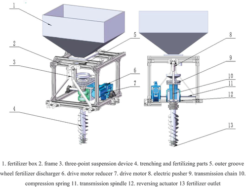
The trenching and fertilizing device mainly consists of fertilizer box, frame, three-point suspension device, trenching and fertilizing component, outer groove wheel fertilizer distributor, driving motor reducer, driving motor, electric push rod, transmission chain, compression spring, transmission main shaft and reversing transmission device, as shown in Figure .
Figure 1. Overall structure diagram of circular furrow fertilization device in Mountain orchard.
2.2. The working principle of open trench fertilization
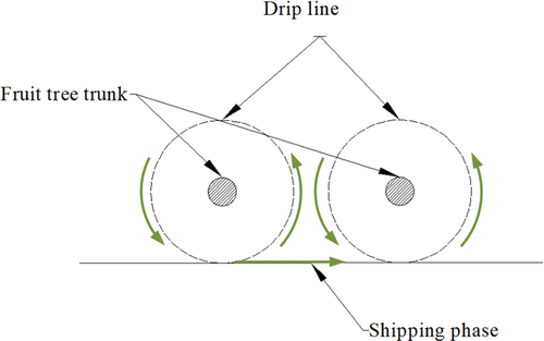
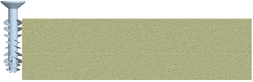
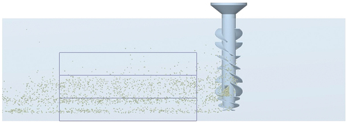
The trenching and fertilizing device is mounted on the tractor by a three-point suspension device, and the control mode is used to move the trenching and fertilizing device to the specified operation site. When the trenching and fertilizing device is near the drip line of the fruit tree canopy, it enters the operation state. The electric push rod gradually extends, and the compression spring gradually pushes the rotating trenching and fertilizing component into the soil until it is vertical. At this time, the outer groove wheel fertilizer distributor starts to operate. The trenching and fertilizing device performs trenching and fertilizing operation along the drip line of the fruit tree. At this time, granular organic fertilizer enters the hollow shaft of the vertical spiral trenching and fertilizing component through the hopper, and falls from the two side fertilizer outlets and the bottom fertilizer outlet to the soil under the joint action of anti-blocking spiral and trenching and fertilizing component. The segmented spiral outside the trenching and fertilizing component lifts the granular organic fertilizer to a certain height and mixes it with soil to complete the trenching and fertilizing operation. The operation process is shown in Figure .
Figure 2. Working principle diagram.
3. Design and optimization of segmented spiral trenching device
3.1. Structural design of segmented spiral trenching components
Spiral blades play a role of rotating, cutting, lifting, and conveying soil particles to the rear of the component or the surface of the ground. Common spiral blades can be divided into conical spiral blades, cylindrical equidistant spiral blades and cylindrical variable pitch spiral blades. As shown in Figure .
Figure 3. Spiral blade curve type.
Conical spiral blades cut trapezoidal grooves, which are widely used in vertical spiral trenching tools. Its structure has the effect of alleviating soil blockage and reducing soil pressure, but it has weak soil lifting ability. Cylindrical variable pitch spiral blades can effectively alleviate the problem of soil congestion between the blades during the process of soil conveying and lifting, and have good soil lifting and conveying effect, so they are widely used in vertical spiral trenching tools. However, according to the requirements of trenching and fertilizing agronomy and soil conditions in hilly and mountainous orchards in southwest China (China soil database. Citation2018), the trenching device does not need to lift a large amount of soil to the surface, but only needs to convey the cut and broken soil at the front to the groove at the rear of the trenching device, and needs a certain lifting ability at the bottom to mix the broken soil with the fertilizer applied at the bottom. Therefore, cylindrical equidistant spiral blade structure is selected.
The motion trajectory is shown in Figure . When the busbar rotates around the central axis at a constant speed and rises spirally, the end point a on the blade surface also rotates around the Z axis at a constant speed. The motion trajectory of the end point a is an equidistant cylindrical spiral. Its motion trajectory can be expressed as:
Figure 4. Schematic diagram of spiral blade curve structure.
In the formula, R is the radius of the outer circle of the spiral blade, mm; P is the pitch of the spiral blade, mm; θ is the angle that the end point a rotates around the Z axis, rad.
When the equidistant cylindrical spiral is unfolded on the ZOY plane, it is a straight line passing through the origin. α is the spiral angle of the spiral blade, which can be expressed as .
The height in the Z-axis direction was taken as 300 mm. In this study, the agronomic requirements for fertilization of orchards in hilly mountainous areas of southwest China were investigated. The results showed that the soil layer for effective fertilization of orchards in this region is shallow (about 300 mm). The soil parent material was mainly developed from the Quaternary Late Pleistocene yellow clay and subclay. The soil depth was 0 ~ 200 mm, which was dark yellowish brown with grain-intercalated block structure. The subsoil layer soil (200 ~ 300 mm) is more compact, slightly lighter in color, yellowish brown, with prismatic or massive structure.
Based on the agronomic requirements for fertilization in orchards in hilly and mountainous regions of China, this study selected a center axis radius of 30 mm and an inner diameter of 24 mm for the vertical spiral furrow opener to reduce operating power consumption while ensuring that the fertilizer distribution component would not become clogged during the fertilization process.
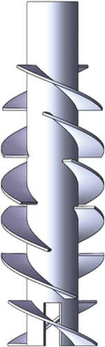
The radius of the segmented spiral blades was 60 mm. During the furrowing and fertilization process, priority was given to achieving “upturning and loosening” effects, which ensured adequate mixing of the fertilizer with soil at an appropriate depth range, avoiding the concentration of fertilizer in the topsoil and promoting better utilization of the fertilizer.
The pitch range of the helical curve for the spiral blade was 80 mm ≤ P ≤270 mm. During furrow opening and fertilization, the spindle of the opener moved simultaneously with the external helical blades to lift up and mix the fertilizer with soil; however, the effective mixing work has yet to be completed. Therefore, based on the design principles of the variable pitch cone furrower (Meng et al., Citation2011), when the helix angle was greater than or equal to 12°, the effect of lifting up soil was good. However, a larger pitch distance would significantly increase the excavation power consumption of the main spindle and the acceleration and scattering energy consumption of the soil. Previous studies showed that the operating power of the spiral opener was lower when the helix angle was less than or equal to 59°. According to the formula α = arctan(p/2πR), with the design value R set to 30 mm for the furrow opener’s spindle, the pitch range for the helical curve of the vertical spiral furrow opener’s blade was calculated as within a certain numerical range. As shown in figure .
Figure 5. Segmented spiral blade structure and arrangement.
3.2. Theoretical analysis of trenching operation process
In the process of using the segmented spiral ditching device, the spiral blade compresses and crushes the soil ahead of the machine’s travel direction, and then transfers it to the back of the trench and the surface by accelerating it. Thus, the operation power consumption of the device consists of digging power consumption, soil conveying power consumption and soil acceleration and scattering power consumption. However, since only a small amount of soil was thrown to the surface after being cut by the blade in this study, we did not analyze the power consumption of soil acceleration and scattering.
3.2.1. Excavation power consumption
The power consumption caused by the soil excavation of the spiral blade during the operation is the digging power consumption. Taking a segment of microelement dS of the excavation edge surface of the spiral blade for theoretical analysis, its force analysis is shown in Figure .
Figure 6. Stress analysis of spiral blade during operation.
The spiral blade is approximated as a constant-pitch cylindrical helix. The soil exerts two main forces on the spiral blade during digging: the normal force F1 that is perpendicular to the blade and the radial force F2 that is parallel to the blade. When the blade compresses and crushes the soil in front of it, the resistance moment acting on a differential element dS of the blade is:
Where, is the helix angle of the spiral blade, °; R is the average radius of dS×t to the center of the spiral blade, mm.
According to existing studies:
Where, C is the cohesion coefficient of soil, N/m2; is the internal friction angle of soil, °;
is the soil-spiral blade external friction angle, °.
t is the average feed per revolution of the spiral blade. When trenching and fertilizing in orchards, the traveling speed is low. Therefore, the feed per revolution of the spiral blade is small when cutting the soil, and it can be regarded as a continuous cutting operation. Then the average feed per revolution t can be expressed as:
Where, is the forward speed of the machine, m/s;
is the rotational speed of the trenching spindle, r/min; z is the number of helical heads, pcs.
By inserting equations 3 and 4 into equation 2 and integrating, the digging resistance moment of the entire spiral blade is derived:
Where, s is the length of all the spiral blades involved in excavating the soil, mm.
The differential element dS on the spiral blade can be expressed as:
From the equation of the equidistant cylindrical helix (equation 1), it can be known that:
By substituting equations 6 and 7 into equation 5 and solving, we obtain:
Where is the angle corresponding to the cutting part of the helical blade curve for the whole segment, rad.
But in the working process, only half of the complete helical blade is digging the soil, and the segmented helical blade is only 2/3 of the length of the complete helical blade. Therefore, the actual digging resistance moment is:
Then the excavation power consumption W1 can be expressed as:
Therefore, it can be seen from equation 9 that under the condition of a certain forward speed , the rotational speed
and the helical angle
of the helical blade have an influence on the digging resistance moment during the operation.
3.2.2. Power consumption for conveying
The energy consumed by the soil to overcome its self-weight and the friction of the helical blade in the conveying process is called the conveying power consumption.
① Work done by gravity
Figure shows the cylindrical soil block cut by the helical blade per revolution. The height of the cylinder is H. The arcs AB and CD are the positions of the outer circle of the helical blade before and after operation, respectively. AC and BD are the feed per revolution of the helical blade t.
Figure 7. Soil cutting amount per revolution of cutter.
Then the work W2 done by the spiral blade to lift the soil block to a height h and overcome gravity is
Where, g is the gravitational acceleration, 9.8 m/s2; γ is the soil density, kg/m3;
S is the surface area of the section ABCD, which can be expressed as:
②Work done by friction with the trench wall
Take a soil element dm, then the frictional resistance of the soil element with the ditch wall under the rotation of the spiral blade can be expressed as:
In the formula, v is the component velocity of the soil element perpendicular to the spiral blade, m/s; μ is the external friction coefficient of the soil.
Then the power consumption W3 due to the friction between the soil and the ditch wall is:
In the formula, l is the distance that the soil element is transported to fall on the spiral blade, mm; s is the total length of the blade edge of the spiral blade involved in the ditching operation, mm.
③Friction work of spiral blade
Taking the soil micro-element dm, the frictional force between the soil micro-element and the spiral blade can be expressed as:
Then the work W4 done by overcoming the friction between the soil and the spiral blade can be expressed as:
Where, l is the distance that the soil element is transported to fall on the spiral blade, mm; s is the total length of the blade edge of the spiral blade involved in the ditching operation, mm.
Therefore, from the above analysis, it can be seen that under the condition of constant forward speed, the rotational speed and spiral angle of the segmented spiral ditching device have a great influence on the power consumption in the ditching operation. In the follow-up research, it needs to be optimized to reduce the power consumption in the ditching operation.
3.3. Inlet blade design
The soil-cutting blade plays a role of centering and cutting the soil below the segmented spiral blade to facilitate the soil entry. According to the agricultural machinery design manual, the soil-cutting blade can be classified into four types: flat-angle triangle, twisted-wing triangle, conical small spiral and forked, as shown in Figure . Considering that the implement in this paper is designed with a hollow shaft, the planar triangular, twisted triangular and forked soil-cutting blades will increase the power consumption of ditching. Therefore, the helical soil-cutting blade is selected in this paper. As shown in Figure , the soil-cutting blade is also designed with a hollow shaft and a double helix to improve the stability of ditching.
Figure 8. Type of embedded blade.
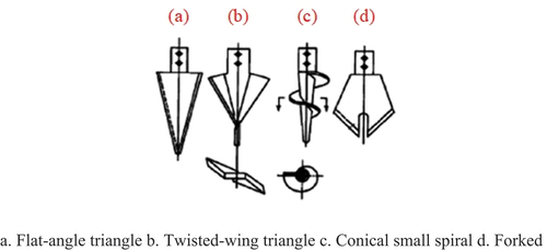
Figure 9. Structure diagram of embedded blade (unit: mm).
4. Trenching component discrete element simulation optimization test
4.1. Soil particle simulation modeling
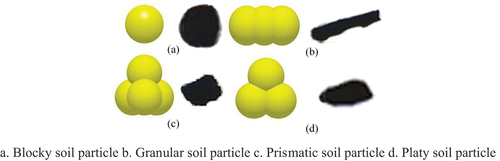
Previous studies have shown that the clay loam particles can be mainly divided into four shapes (Zeng et al., Citation2023): blocky, granular, platy and prismatic. Therefore, to better simulate the real soil conditions, four kinds of soil model particles are established by using the spherical particle accumulation provided by EDEM. The blocky particle is approximated by a single sphere model; the granular particle is approximated by three parallel sphere models; the platy particle is approximated by three triangular sphere models; and the prismatic particle is approximated by four stacked sphere models. In order to improve the simulation speed, the radius of each sphere model is set to 3 mm. The particle models are shown in Figure , and the spatial coordinates of each sphere particle are shown in Table .
Figure 10. Soil particle model.
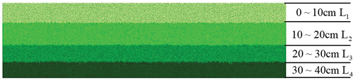
In this paper, the soil particle model is established by using EDEM software and placed in a BOX of 1500 mm × 400 mm × 450 mm as a soil container. According to the existing research (Zhou et al., Citation2013), the soil particle shape ratio is blocky: granular: platy: prismatic = 34:26:20:20, so in this paper simulation, the generation ratio of each particle shape is set to blocky 34%, granular 26%, platy 20%, and prismatic 20%. At the same time, in order to improve the simulation realism, the radius of each particle shape is set to follow a normal distribution with a mean of 1 and a standard deviation of 0.05. The soil accumulation depth is set to 40 cm and divided into 4 layers of 10 cm each, as shown in Figure , which are denoted as L1 layer (0⁓10 cm), L2 layer (10⁓20 cm), L3 layer (20⁓30 cm), and L4 layer (30⁓40 cm). Each layer generates 250,000 soil particles, totaling 1,000,000 soil particles. Among them, there are 340,000 blocky particles 260,000 granular particles 200,000 platy particles, and 200,000 prismatic particles.
Figure 11. Soil simulation model.
In order to ensure the realism of the simulation, the JKR model is used to set the parameters for the soil models of L1 and L2 layers to simulate the cohesion of the soil in the hilly mountainous area and the relatively loose upper soil. The Hertz-Mindlin with bonding model (Potyondy & Cundall, Citation2004; Ucgul et al., Citation2014) is used to set the parameters for the soil models of L3 and L4 layers to simulate the relatively compacted lower soil. The parameters in the JKR model and Bonding model and the basic contact parameters of the soil model are referred to the existing research (Asaf et al., Citation2007; Xiang et al., Citation2019; Zeng et al., Citation2023), as shown in Table below.
Table 1. Spatial location parameters of each model
Table 2. Parameters of soil simulation model
4.2. Comparative analysis based on discrete element method simulation with single factor
In order to investigate the effects of rotational speed and pitch on the power consumption and soil disturbance of ditching device, and compare the differences between segmented spiral and complete spiral in power consumption and lifting performance, this study conducted a single factor simulation experiment.
4.2.1. Determination of the parameter range
During the operation process, the ditching fertilization spindle follows the crawler chassis to advance on one side, and self-rotates to cut the soil on the other side, and it meets the following relation:
In the formula, represents the cutting feed rate (m/r),
represents the forward speed (m/s),
represents the number of spindle helix heads(pcs), and
represents the spindle speed (r/min).
According to the requirements of orchard ditching and fertilization agronomy and agricultural machinery design (Huang, Citation1996; Zhang et al., Citation2021), the range of parameters such as ditching efficiency, forward speed, cutting distance per spindle rotation, and number of helical blade heads were determined. The ditching efficiency should be no less than 300 m/h; the forward speed should not exceed 1200 m/h to ensure that the amount of fertilizer applied meets agronomic requirements; the cutting distance per spindle rotation should not be greater than 0.03 m to reduce power consumption; and the number of helical blade heads is set to 2 to balance the relationship between soil acceleration and throwing power consumption and soil blockage power consumption. By substituting these parameters into formula 17, the range of spindle speeds for ditching is obtained as 120 r/min to 500 r/min.
4.2.2. Experimental design for single-factor comparative simulation tests
On the basis of determining the parameter range in Section 3.1, this section conducts single-factor tests by selecting a forward speed at the intermediate level of 0.21 m/s and varying the remaining parameters at five levels. For the single-factor test of rotation speed, the pitch is set at the intermediate value. Similarly, for the single-factor test of pitch, the rotation speed is set at the intermediate value. The specific values for each parameter are presented in Table .
Table 3. Single factor comparative simulation test scheme
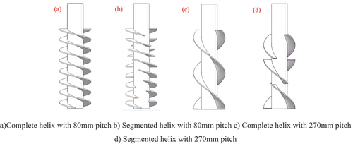
According to the table above, both a complete helical-tillage device and a segmented helical-tillage device were modeled in the SolidWorks software. The segmented helix maintains the same helix angle as the complete helix, with each blade sweeping one-third of a circle. Furthermore, to reduce the concentrated stress on the tillage spindle during cutting, the blades are arranged along the helical line. To minimize simulation time, the model was simplified, as shown in Figure .
Figure 12. Comparison diagram of simulation model.
The simulation model for single-factor comparative experiments was constructed by importing the models described above into EDEM, a discrete element software, and coupling it with the soil model built in the previous section, as shown in Figure . The material properties of the tillage spindle and the contact parameters between the spindle and soil are listed in Table . To ensure the accuracy of the simulation experiment and reduce the total simulation time, the time step of the simulation calculation was set to 20% of the Raleigh time step. The simulation time was set to 5 seconds, the data saving interval was set to 0.1 seconds, and the operation mesh diameter was set to 3 R. For the single-factor test of rotational speed, a median value of helix pitch was used, and for the single-factor test of helix pitch, a median value of rotational speed was used. Ten sets of tests were performed for each type of tillage spindle (complete and segmented helix), with each test being repeated three times, and the simulation results were averaged.
Figure 13. Simulation model of vertical spiral trenching.
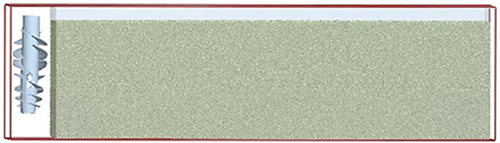
Table 4. Steel related simulation parameters
5. Result
5.1. Working resistance torque
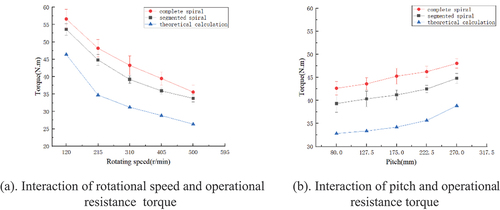
After the simulation experiment was finished, the post-processing module of the EDEM software was used to export the numerical values of the working resistance torque of the trenching main shaft in the time interval from 1s to 5s. The average values of each group of experiments were calculated and taken as the experimental values. At the same time, the theoretical values of the working resistance torque of each group of experiments were obtained by theoretical calculation. The results are shown in Figure .
According to the data in Figure , as the rotational speed gradually increased, the working resistance torque of the complete spiral trenching main shaft decreased from 56 N·m to 35 N·m, while that of the segmented spiral trenching main shaft decreased from 53 N·m to 33 N·m. This downward trend is consistent with the downward trend of the theoretical calculated values, indicating that the constructed simulation model can effectively simulate the mechanical characteristics of soil. In addition, the increase of rotational speed can reduce the working resistance torque in the trenching process, thus reducing the power consumption.
As shown in Figure , as the pitch gradually increased, the working resistance torque of the complete spiral trenching main shaft increased from 42.64 N·m to 48.04 N·m, while that of the segmented spiral trenching main shaft increased from 39.32 N·m to 44.81 N·m. This is mainly because the increase of pitch leads to the increase of acceleration and scattering power consumption of soil particles, resulting in the increase of working resistance torque. The upward trend of simulation experimental values is consistent with that of theoretical calculation, indicating that the experimental model used can effectively simulate the working state in trenching process.
Based on the above analysis, under the same structure and operation parameters, compared with complete spiral trenching device, segmented spiral trenching device can effectively reduce power consumption in operation process. This is mainly due to segmented spiral trenching device reducing soil particle lifting power consumption and scattering power consumption.
Figure 14. Effect of factor interactions on operating moments.
5.2. Longitudinal displacement of soil particles
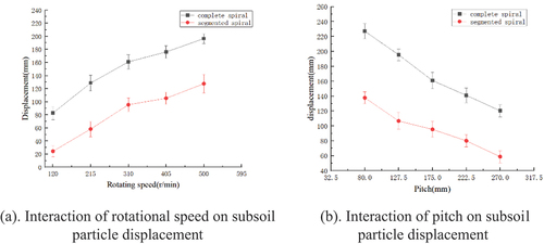
Using the post-processing module of EDEM software, 100 soil particles in the depth range of 20-30 cm were calibrated by Manual selection tool. Then, using the simulation data export function of EDEM software, the displacement of these calibrated soil particles along Z axis at simulation time of 5 seconds was exported. In this process, the forward direction of the trenching main shaft was along the positive direction of X axis. For each group of experiments, the average value of 100 soil particle displacements was calculated as the experimental result, as shown in Figure .
As can be seen from Figure , as the rotational speed increased, the soil particle lifting displacement caused by complete spiral increased from 80 mm to 191 mm, while that caused by segmented spiral increased from 22 mm to 112 mm. This indicates that rotational speed has a significant effect on longitudinal displacement of soil particles. Under the same structure and operation parameters, segmented spiral can effectively reduce the displacement of soil particles along Z axis and reduce the disturbance of underlying soil, achieving the effect of “upturning and loosening”. As can be seen from Figure , as the pitch gradually increased, the soil particle lifting caused by complete spiral trenching main shaft decreased from 226 mm to 120 mm, while that caused by segmented spiral trenching main shaft decreased from 137 mm to 58 mm. Therefore, the increase of pitch can reduce longitudinal displacement of soil particles, and segmented spiral can more effectively reduce lifting of underlying soil particles when pitch increases.
Figure 15. Interaction of factors on soil particles.
The test results of the single-factor test of the trenching spindle device show that the rotational speed and the auger have a more significant effect on the operating resistance moment and soil particle displacement during trenching. The trend of the simulation is consistent with the theoretical calculation, which shows that the simulation model can effectively simulate the process of trenching and fertilizer application. The segmented spiral trenching device can effectively reduce the operating resistance moment and the displacement of the soil particles in the trenching process. Therefore, orthogonal tests will be carried out to determine the reasonable structural and operational parameters of the segmented spiral.
5.3. Test results and analysis of trenching device
The simulation model for the orthogonal experiment is shown in Figure , which simplifies the tillage and fertilization components to include only the feeding hopper, rotating spindle, helical blade, tillage blade, and anti-clogging spiral to reduce the computational time. The soil particle model is consistent with that used in the single-factor simulation experiment, while the fertilizer particle model is consistent with that described in Section 3.2. Other materials and simulation parameters remain the same as those used in the single-factor simulation experiment discussed above. The fertilizer particle generation rate is set to 0.2 kg/s based on an application rate of 0.5 t/h.
Figure 16. Discrete element simulation model of trenching and fertilizing parts.
Based on the single-factor simulation experiment in the previous section, it was determined that increasing the rotational speed would result in a reduction of the tillage resistance torque but an increase in the displacement of the bottom layer of soil particles. Conversely, increasing the helix pitch would cause an increase in the tillage resistance torque but a decrease in the position of the bottom-layer soil particles. Therefore, suitable ranges for rotational speed (x1) and helix pitch (x2) were selected as 215–405 r/min and 127.5–222.5 mm, respectively. The arrangement and results of the orthogonal experiment are presented in Table .
Table 5. Orthogonal simulation test scheme and results
To obtain the degree of mixing between fertilizer particles and soil in each simulation experiment, the soil particles were hidden after the simulation was completed. A stable operation phase was selected, and the Grid Bin Group component in EDEM’s post-processing module was used to count the number of fertilizer particles in each layer. A stable segment of length 600 mm was chosen, and three layers were selected by box-selecting the 30–40 cm, 20–30 cm, and 10–20 cm intervals, respectively, to count the number of fertilizer particles, as shown in Figure .
Figure 17. Particle statistical extraction process.
Two second-order regression models were established using Design-Expert 12.0 software to explore the relationships between tillage resistance torque and fertilizer-soil mixing degree with the two factors. The quadratic regression equations for the two models are presented below:
In this expression, x1 is the rotational speed in r/min; x2 is the pitch in mm.
Experimental data was analyzed using Design Expert 12.0 software for analysis of variance (Table ). The results indicate that both models exhibit high goodness of fit (p(Torque) = 0.0005 < 0.01). Furthermore, all independent variables were found to have significant correlation with the dependent variable (i.e., Torque), thereby indicating excellent credibility and accuracy of the regression model. Specifically, the torque regression model possessed a high coefficient of determination (R2 = 0.9972) and adjusted coefficient of determination (Radj2 = 0.9925) were close to 1, which implies very good fitting of the regression model and high reliability of the regression equation. Additionally, the coefficient of variation (CV) of the torque model was 1.74%, while the Adeq Precision was 38.0771 > 4; both indicating high reliability and precision of the model.
Figure 18. Influence trend of interaction items.
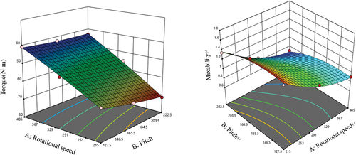
Table 6. Analysis of variance of resistance torque regression model
According to the regression equations of torque and mixing degree, the corresponding response surface is obtained (As shown in Figure ). As the helical pitch and rotational speed of the trenching device increase, the torque of the trenching operation gradually increases. Among them, the increase in the rotational speed of the trenching device has a more significant impact on the trenching torque, and the resistance torque decreases with the increase in rotational speed. The expansion of the helical pitch of the trenching device has a relatively smaller impact on the trenching torque, and the resistance torque also decreases as the pitch increases. In addition, the mixing degree decreases with the increase in rotational speed and the expansion of the helical pitch.
5.4. Simulation verification test
When the helical pitch is in the range of 127.5–222.5 mm, the trenching speed is 215–405 r/min, and the segmented helical combination is used, the experimental factors are optimized to obtain the optimal experimental factor level. A mathematical model including optimized helical pitch, trenching speed, and segmented helix parameters is established. Based on the boundary conditions of the experimental factors, the regression model is analyzed to obtain the following mathematical model:
In pursuit of high efficiency and low energy consumption in agricultural machinery operations, the Optimization function provided by Design-Expert software is utilized to achieve the demand goal of maximizing the depth of trenching mechanical operation indicators while minimizing the energy consumption of trenching operations. After optimization analysis, the following combination of influential factor parameters is obtained: helical pitch of 138 mm, trenching speed of 350 r/min, and trenching operation torque of 47.35 N·m.
6. Discussion
This paper aims to study the influence law of a segmented spiral ditching and fertilizing device, by combining theoretical analysis and simulation experiments. The interaction models between soil and ditching device, and between soil and fertilizer particles are discussed. Response surface method is used to design experiments and explore the interactive effects of various factors. To meet the agronomic requirements of orchard fertilization as much as possible, an optimization model is constructed with the objectives of minimizing the operation torque and approaching the mixing degree to 1, and the accuracy of the optimization model is verified.
Wang et al. (Wang et al., Citation2023) studied the influence of different shapes of ditching blades on the ditching performance in paddy fields; Hu et al. (Hu et al., Citation2021) found that arc-shaped blades could reduce soil adhesion and blockage, and improve ditching quality; Ma et al. (Ma et al., Citation2009). developed a variable double-pitch spiral orchard ditching device, which had the remarkable features of low power consumption, integrated soil cutting, lifting, and scattering, and smooth rectangular ditch walls; Zhang et al. studied the influence of different working parameters on the power consumption of spiral ditcher, and found that both forward speed and rotational speed would increase power consumption. Zhao et al. (Zhao et al., Citation2021) designed a segmented corn ditching and sowing device for deep fertilization no-till planter in Northeast China, aiming at the problems of poor uniformity of ditching depth and high operation resistance. Through field comparison experiments with other different ditching devices, they found that the segmented ditching device had the advantages of high uniformity of ditching depth, low soil disturbance, and low operation resistance. However, they did not optimize the parameters.
To study the influence law of ditching operation parameters on ditching quality, variance analysis was performed on the data using response surface method. The results of variance analysis showed that: the regression model of rotational speed was extremely significant, the regression model of pitch was significant, and the lack of fit was not significant. Moreover, the relationship between each parameter index was analyzed by response surface method. During the operation of the ditching device, the torque would decrease with the increase of rotational speed, thus reducing the operation power consumption.
The optimization experiment results met the quality performance indicators of organic fertilizer ditching operation. The evaluation indicators of this paper only included operation torque, power consumption and mixing degree, without considering other factors that might affect the growth and yield of fruit trees, such as soil structure, moisture, nutrients, etc., which need to be monitored and evaluated in future research. On the other hand, the influence of frame, guide hood, drive engine and other factors on ditching operation was ignored in the theoretical analysis.
7. Conclusion
This paper introduces the structure and working principle of the furrow opener and conducts a theoretical analysis of its power consumption during operation. Under constant forward speed, the rotational speed and helix angle of the segmented helical furrow opener have a significant impact on power consumption during furrowing operations, laying the theoretical foundation for subsequent simulation analysis.
Based on the theoretical analysis, we established an interaction model of the soil furrow opener using EDEM software and used single-factor experiments to determine the range of rotational speeds from 215 r/min to 405 r/min and pitch ranging from 127.5 mm to 222.5 mm.
To verify the reliability of the theoretical and simulation analysis, we designed a response surface test program, conducted numerical simulations of the furrow opener’s working process using EDEM software, and simulated the relationship between working parameters (including forward speed and furrowing rotation speed) and structural parameters (such as the helix blade pattern) and operating torque during furrowing operations. By minimizing operating torque while approaching a mixed fertilizer ratio of 1, we optimized the structural and operational parameters of the segmented helix, resulting in an optimal operating rotational speed of 350 r/min and an optimal pitch of 138 mm for the helix blade, as indicated by the simulation results.
The evaluation indicators of this paper only include operation torque, power consumption, and mixing degree, without considering other factors that may affect the growth and yield of fruit trees, such as soil structure, moisture, nutrients, etc. Our research experiment site was a single sticky loam soil. Future research may include combining the ditching and fertilizing device with various soils, conducting systematic field experiments, further optimizing the device structure and operation parameters, and improving operation effect and efficiency.
Ethical approval
The authors confirm that there are no ethical issues in the publication of the manuscript.
Author’s contributions
All authors contributed to the study conception and design. Material preparation, data collection and analysis were performed by Can Xie. The first draft of the manuscript was written by Cong Zhang and all authors commented on pre-vious versions of the manuscript. All authors read and approved the final manuscript.
Disclosure statement
The authors declare that we have no known competing financial interests or personal relationships that could have appeared to influence the work reported in this paper.
Additional information
Funding
Notes on contributors
Cong Zhang
Cong Zhang is a postgraduate at College of Engineering and Technology, Southwest University, Chongqing.
Can Xie
Can Xie is a postgraduate at College of Engineering and Technology, Southwest University, Chongqing.
Chen Ma
Chen Ma is a PhD student at College of Engineering and Technology, Southwest University, Chongqing.
Lihong Wang
Lihong Wang is a Professor at Southwest University with research interests in the key technology and equipment research and development of mechanization of forest and fruit production.
Ying Zhao
Ying Zhao is an associate professor at Hainan University with research interests in weeding equipment technology for the forest and fruit industry.
Chengsong Li
Chengsong Li is a Professor at Southwest University with with research interests in key technologies and equipment for mechanization of the whole production process of forest and fruit industry.
References
- Argüello, D., Chavez, E., Lauryssen, F., Vanderschueren, R., Smolders, E., & Montalvo, D. (2019). Soil properties and agronomic factors affecting cadmium concentrations in cacao beans: A nationwide survey in Ecuador. Science of the Total Environment, 649, 120–20. https://doi.org/10.1016/j.scitotenv.2018.08.292
- Asaf, Z., Rubinstein, D., & Shmulevich, I. (2007). Determination of discrete element model parameters required for soil tillage. Soil and Tillage Research, 92(1), 227–242. https://doi.org/10.1016/j.still.2006.03.006
- Chen, H., Zheng, J., Lu, S., Zeng, S., & Wei, S. (2021). Design and experiment of vertical pneumatic fertilization system with spiral Geneva mechanism. International Journal of Agricultural and Biological Engineering, 14(4), 135–144. https://doi.org/10.25165/j.ijabe.20211404.6575
- Deng, H., & Jing, L. (2008). Structural analysis and design of small diameter vertical spiral trencher. Construction Machinery and Equipment, 03, 9–13+113. https://doi.org/10.3969/j.issn.1000-1212.2008.03.003
- Guo, Z., Chen, H., Yi, H., & Li, D. (2019). Research and prospect of the status quo of fertilization machinery in orchard. Xinjiang Agricultural Mechanization, 06, 22–25+31. https://doi.org/10.13620/j.cnki.issn1007-7782.2019.06.006
- Huang, W. (1996). Vertical shaft screw trencher design. Xinjiang Agricultural Mechanization, 3, 31–32. https://doi.org/10.13620/j.cnki.issn1007-7782.1996.03.031
- Hu, S. S., He, L. A., Hu, Y. N., & Wang, C. Y. (2021). Failure mechanism of diamond saw blade sawing concrete. Materials Science Forum, 1018, 169–176. https://doi.org/10.4028/www.scientific.net/MSF.1018.169
- Liang, B., Ma, C., Fan, L., Wang, Y., & Yuan, Y. (2018). Soil amendment alters soil physicochemical properties and bacterial community structure of a replanted apple orchard. Microbiological Research, 216, 1–11. https://doi.org/10.1016/j.micres.2018.07.010
- Liang, X., Zhang, R., Gleason, M. L., & Sun, G. (2022). Sustainable apple disease management in China: Challenges and future directions for a transforming industry. Plant Disease, 106(3), 786–799. https://doi.org/10.1094/PDIS-06-21-1190-FE
- LIU Shuangxi, X. C. (2020). Research status and development analysis of base-fertilizer application equipment of orchard. Nongye Jixie Xuebao/Transactions of the Chinese Society of Agricultural Machinery, 51(S2), 99–108. https://doi.org/10.6041/j.issn.1000-1298.2020.S2.012
- Lv, Z. (1994). Ways to reduce power consumption of vertical screw trenchers. Transactions of the Chinese Society for Agricultural Machinery, 02, 78–83.
- Ma, A., Liao, Q., Tian, B., Huang, H., & Zhou, Z. (2009). Design on spiral orchard ditching equipment and test in the soil bin. Hubei Agricultural Sciences, 48(7), 1747–1750.
- Meng, H., Gao, Z., Kan, Z., & Lin, H. (2011). Design and experiment on dairy cow precision-feeding device based on equal-diameter and variable-pitch. Transactions of the CSAE, 27(3), 103–107.
- Meng, M., & Qu, D. (2022). Understanding the green energy efficiencies of provinces in China: A super-SBM and GML analysis. Energy, 239, 121912. https://doi.org/10.1016/j.energy.2021.121912
- Potyondy, D. O., & Cundall, P. A. (2004). A bonded-particle model for rock. International Journal of Rock Mechanics and Mining Sciences, 41(8), 1329–1364. https://doi.org/10.1016/j.ijrmms.2004.09.011
- Shmulevich, I., Asaf, Z., & Rubinstein, D. (2007). Interaction between soil and a wide cutting blade using the discrete element method. Soil and Tillage Research, 97(1), 37–50. https://doi.org/10.1016/j.still.2007.08.009
- Soil Information System of China (SISChina). (2018). China soil database. China Statistics Press.
- Ucgul, M., Fielke, J. M., & Saunders, C. (2014). Three-dimensional discrete element modelling of tillage: Determination of a suitable contact model and parameters for a cohesionless soil. Biosystems Engineering, 121, 105–117. https://doi.org/10.1016/j.biosystemseng.2014.02.005
- Wang, J., Xu, Y., Wang, C., Xiang, Y., & Tang, H. (2023). Design and simulation of a trenching device for rice straw burial and trenching based on MBD-DEM. Computers and Electronics in Agriculture, 207, 107722. https://doi.org/10.1016/j.compag.2023.107722
- Wang, Q., Yao, Z., Gao, H., Li, H., & Wang, X. (2008). Design and experiment on a Wedge shaped no-tillage opener. Journal of Mechanical Engineering, 44(9), 177–182. https://doi.org/10.3901/JME.2008.09.177
- Xiang, W., Wu, L., Lv, J., Quan, W., Ma, L., & Liu, J. (2019). Calibration of simulated physical parameters of clay loam soils based on stacking tests. Transactions of the Chinese Society of Agricultural Engineering, 35(12), 116–123.
- Xiao, H., Ying, Z., Ding, W., Song, M., Yu, H., Yuan, Z., Yan, H., & Song, Z. (2017). Design and experiment on blade shaft of 1KS60-35X type orchard double-helix trenching and fertilization machine. Transactions of the Chinese Society of Agricultural Engineering, 33(10), 32–39.
- Zeng, Y., Chen, C., Quan, W., Xie, S., Shi, F., Ma, Z., & Wu, M. (2023). Calibration parameter of soil discrete element Based on area difference method. Agriculture, 13(3), 648. https://doi.org/10.3390/agriculture13030648
- Zhang, H., Xu, C., Liu, S., Jiang, H., Zhang, C., & Wang, J. (2021). Design and experiment of orchard Double Row ditching-fertilizer machine with automatic depth adjustment. Transactions of the Chinese Society of Agricultural Machinery, 52(1), 62–72.
- Zhao, S., Gao, L., Yuan, Y., Hou, L., Zhang, X., & Yang, Q. (2021). Maize straw motion law in subsoiling operation using discrete element method. Transactions of the Chinese Society of Agricultural Engineering, 37(20), 53–62.
- Zhou, B., Fan, Q., Chen, B., & Wang, Z. (2013). Numerical simulation of soil cutting by biaxial vertical auger trencher. Hubei Agricultural Science, 52(8), 1938–1942.