 ?Mathematical formulae have been encoded as MathML and are displayed in this HTML version using MathJax in order to improve their display. Uncheck the box to turn MathJax off. This feature requires Javascript. Click on a formula to zoom.
Abstract
A new type of metamaterial-inspired patch antenna designed for having multi-resonance and minituarization has been elucidated. A novel metamaterial formed by combining 2 segment labyrinth and capacitive loaded strip has been designed by combining negative permeability and negative permittivity characteristics respectively, to form a Double Negative Group metamaterial. By adding 4 unit cells to the microstrip patch antenna resonating at 30 GHz, secondary resonances have been created around 8.5, 17.7, 20 and 23.7 GHz. Seventy-two per cent miniaturization of the structure is obtained using metamaterial-inspired antenna, but at the cost of reduction in bandwidth.
Keywords:
Public Interest Statement
The main aim of this work is to obtain miniaturization and multi-resonance in the antenna using metamaterial. The need of an hour is smaller antenna which can give us same performance parameters as the larger antenna and multi-resonance is used in military applications. This is done without altering the antenna’s dimensions, instead by inserting a new and novel metamaterial array on the patch and inside the substrate of the antenna.
1. Introduction
Rectangular Microstrip Patch Antenna (RMPA) consists of a rectangular patch over a microstrip substrate with many applications in field of communication systems. The requirement of smaller size systems and also smaller antennas in RADARS and radio sensors is increasing. Therefore, the antenna miniaturization becomes an important requirement in wireless communication systems. Various techniques like shorting posts (Waterhouse, Targonski, & Kokotoff, Citation1998), slotting of patch (Huang, Citation2001), and using high-permittivity dielectric substrate (Trippe, Bhattacharya, & Papapolymerou, Citation2011) have been used for miniaturization, but are not able to miniaturize the antenna to an acceptable extent and also increase the flow of surface waves. Also, the use of antenna for applications such as GPS, WLAN, requires multi-band antenna with compactness and low cost. Therefore, metamaterial structures are used.
“Metamaterials” (MTMs) are engineered to modify the bulk permeability and/or permittivity of the medium. It is realized by placing periodically, structures that alter the material parameters, with elements of size less than the wavelength of the incoming electromagnetic wave. It results in “meta” i.e. “altered” behaviour or behaviour unattainable by natural materials. Slight changes to a repeated unit cell can be used to tune the effective bulk material properties of a MTM, replacing the need to discover suitable materials for an application with the ability to design a structure for the desired effect. Their characteristics include negative permittivity, negative permeability and negative refractive index.
2. Antenna design
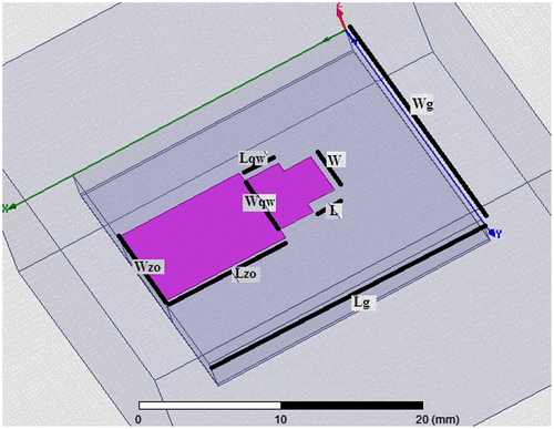
RMPA can be represented as two slots of width, w, and height, h, separated by transmission line of length, l. It is designed to resonate at 3.85 THz frequency with dielectric constant (εr) = 2.33, substrate thickness h = 2 mm, L = 2.17 mm, W = 4.23 mm on a ground plane (Balanis, Citation1997; Pozar, Citation1992). Practically, ground plane is finite with size greater than the patch dimensions by approximately six times the substrate thickness,with length, Lg = 22.15 mm and width, Wg = 24.6 mm. The constructional details are shown in Figure .
Microstrip feed using quarter-wave transformer has been used for feeding the antenna as calculated from Equation (1).
The input impedance is taken at the base of microstrip feed line and is referred to 50Ω. i.e. Z0.(1)
(1)
where Wqw and Lqw represent the width (8.4 mm) and length (9.8 mm) of the quarter-wave transformer as calculated from Zqw i.e. impedance of quarter-wave transformer using Tx-Line software by AWR.
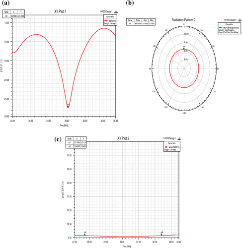
Figure shows the simulation results i.e. Return loss, 3D polar plot of gain, VSWR and radiation pattern in E and H plane.
It can be seen that S11 i.e. return loss is −27.3 dB at 30 GHz and VSWR is 1.09. Bandwidth, the range of frequencies with VSWR < 2, is 10.4 GHz. Peak realized gain is 9.6 dB.
3. Proposed metamaterial
Multiple split rings (2-segment) Labyrinth metamaterial has been proposed having magnetic resonance. It behaves as Mu-Negative Group (MNG). It is constructionally very simple, consists of a 2-segment SRR with RT Duroid Substrate (Bilotti, Toscano, Vegni, & Aydin, Citation2007; Minowa et al., Citation2011). It is designed in such a way that the inclusions are much smaller than the operating wavelength. Such structures can be denoted by quasi-static equivalent LC circuit. Unit cell formed in HFSS is shown in Figure (a) with constructional details in Figure (b) where thickness “t” of the conducting metallic inclusions (N = 2) is 5 μm, height “h” of the substrate is 2 mm, conductivity “ρs” is 0.017 × 10⁻⁶ Ωm, “l” is the side length of the external ring, “u” is the width of the strips, “s” is the separation between two adjacent strips, “g” is the gap width.
Figure 3. Segment labyrinth SRR MTM (a)unit cell designed in HFSS (b)constructional details with tanϐ = 0.01.
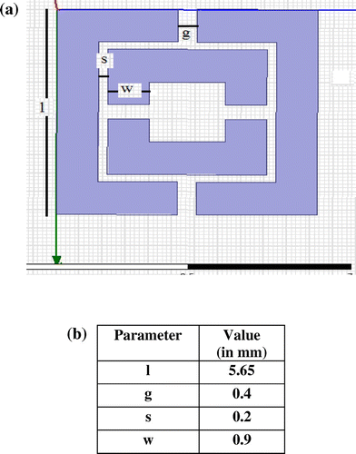
A capacitive-loaded strip (CLS) is a strip line that acts as an electric dipole and mimics long metallic wires (Alhawari, Ismail, Mahdi, & Abdullah, Citation2011). Two strips with dimensions 1.8 mm × 0.4 mm and 5.65 mm × 0.9 mm are designed and joined with each other in T-shape. This whole structure is integrated with 2-segment labyrinth to form a new metamaterial as shown in Figure .
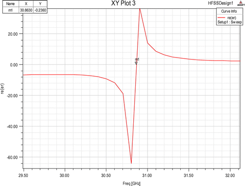
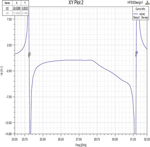
Figures and show the permittivity and permeability characteristics obtained from simulation of unit cell.
Resonance in permittivity is obtained at 30.86 GHz and resonance in permeability is obtained at 31.45 GHz.
The negative permittivity and permeability region extends from 24 to 31.45 GHz. This forms a Double Negative Group (DNG) metamaterial by combining MNG 2-segment labyrinth metamaterial with Epsilon-Negative Group CLS metamaterial.
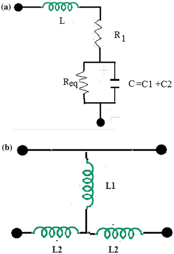
2-segment labyrinth SRR MTM and CLS can be simplified in terms of combinations of parallel RC, series RL and L, respectively. Using transmission line theory (quasi-static regime), we can draw its equivalent circuit as in Figure (a) and (b).
The L is the inductance per unit length of the loop and C is the equivalent capacitance. This circuit in Figure (a) has capacitances from two regions: (1) capacitance from gap “g” in the rings named C1 in parallel with resistance R1 (2) capacitance between the split rings named C2 in parallel with R3. Also, series resistance R1 is to take into account the losses in the conductor and a shunt resistance R2 and R3 are taken to describe the losses in the dielectric substrate as shown in Figure (b). Here, length of the gap plays a significant role and C1 and C2 are of the same order of magnitude.
The expressions for L and C are given by Equations (2) and (3) as below (Ghaznavi Jahromi et al., Citation2013):(2)
(2)
where μ0 is the vacuum permeability, lavg is the average strip length calculated over all the rings.(2.1)
(2.1)
Using Equation (2.1), we get, L is 1.58 × 10⁻⁹ H.
Using expressions, C1 is 9.15 × 10⁻¹⁴ F and C2 is 7.62 × 10⁻¹⁴ F. Thus, the resultant Capacitance by virtue of C1 and C2 is the series combination of two. So,(3)
(3)
Thus C = 16.77 × 10⁻¹⁴ F.
The expression for Lm of CLS in Figure (b) is given by Equation (4) as below (Dai, Wang, Li, & Liang, Citation2013):(4)
(4)
where μ = μ0 is the vacuum permeability and parameter value h = 2 mm and “l” is length and “w” is width of the strip. Upon calculations, L1 = 5.65 × 10⁻⁹ H and L2 = 3.95 × 10⁻⁹ H.
Thus, combining the equivalent circuits of Figure (a) and (b), the resultant L = 4.88 × 10⁻⁹ H and C = 16.77 × 10⁻¹⁴ F.
The resonance of the unit cell can be obtained by putting the resultant L and C in Equation (5).(5)
(5)
The resonant frequency is found out to be 34.95 GHz.
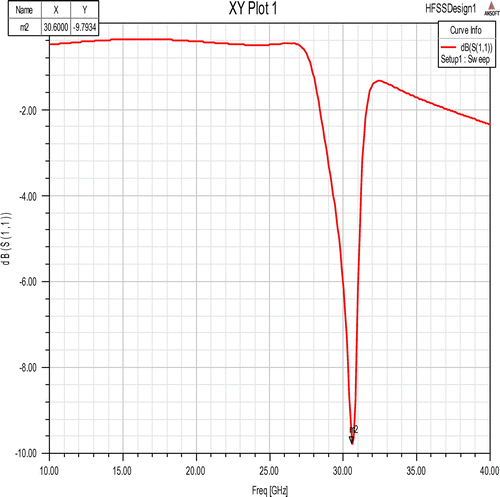
Upon simulating the unit cell in HFSS, the resonant frequency is obtained as 30.6 GHz as shown in Figure .
Therefore, nearly 12% error is found out between simulational and theoretical analysis.
4. Metamaterial rectangular microstrip patch antenna
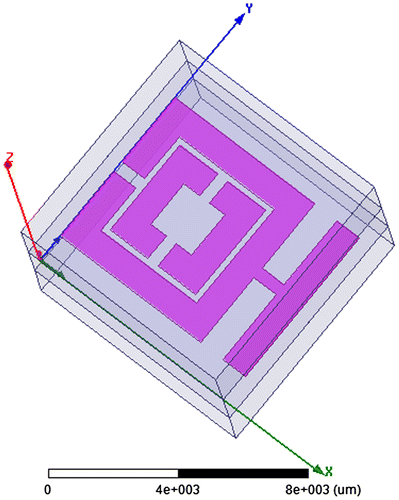
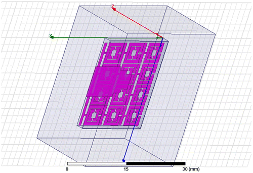
The effect on antenna’s parameters has been studied as shown in Figure , by embedding in the middle of its substrate a metamaterial array (3 × 4) such that the centre of the array coincides with the centre of the antenna substrate. The double negative characteristics of metamaterial, when placed just below the patch, reduce the electrical length of the antenna structure, thereby obtaining miniaturization.
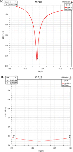
The simulation results are shown in Figure (a) and (b).
VSWR for MTM array inside RMPA substrate is 1.4 and bandwidth is 3 GHz as shown in Figure .
Upon loading the antenna with metamaterial array, the resultant resonant frequency is dependent on its constitutive parameters. Thus, when the constitutive parameters become negative, the resonance occurs in antenna. This leads to shifting of antenna’s resonant frequency to that of the metamaterials resonance frequency. In the proposed antenna, it is shown that by loading a conventional rectangular patch antenna substrate with a DNG metamaterial, a sub-wavelength resonant mode on the patch will be excited (Ghaznavi Jahromi et al., Citation2013).
This new resonance is at 22.9 GHz i.e. “K” band and is useful for satellite communication system. Thus, 24% miniaturization of the antenna has been obtained. Because these metamaterial structures are narrowband, the bandwidth of the proposed antenna is smaller than the conventional antenna.
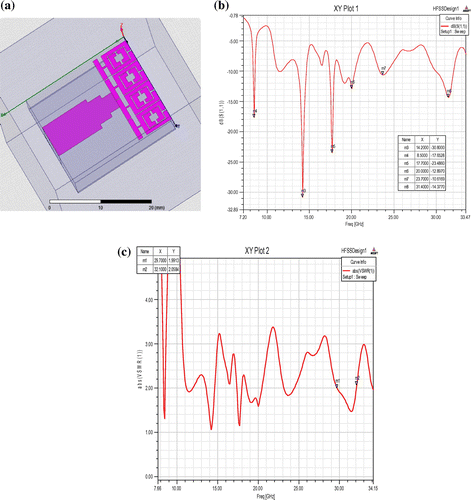
A new design methodology for multi-band rectangular microstrip antenna using metamaterial-inspired technique is proposed (Dai et al., Citation2013). By placing metamaterial structure horizontally adjacent to the radiating patch, multi-band operation occurs as shown in Figure (a).
It can be seen that there are five resonant frequencies, 8.5, 17.7, 20, 23.7 and 31 GHz, respectively. Maximum bandwidth of nearly 2.4 GHz is obtained at the 31 GHz mode. Thus, bandwidth has been reduced.
Four lower resonant frequencies are generated by the introduction of the proposed metamaterial, while the resonant frequency 31 GHz is determined by the dominant mode of the patch cavity. This is useful in GPS and WLAN applications in communication system, where multiple resonances of the antenna are required.
If the mode at 8.5 GHz is considered to be dominant, then nearly 72% miniaturization of the antenna can be obtained.
5. Conclusion
In this paper, novel metamaterial “2-segment labyrinth-CLS” has been designed and implemented using FEM-based software, Ansoft HFSS and compared with equivalent circuit based on microstrip discontinuity with 12% error. Metamaterial-embedded patch antenna has been designed with applications in communication systems, such as GPS, WLAN and satellite communication. The miniaturization in the structure has also been achieved by about 72%. There is trade-off in obtaining reduced bandwidth since the metamaterials are inherently resonant structures.
Additional information
Funding
Notes on contributors
Parul Dawar
Parul Dawar is an assistant professor in Guru Tegh Bahadur Institute of Technology, GGSIPU, Delhi. Her research interests include Electro-magnetic Field waves, Optical Communications and Microwave Electronics. She has authored two books titled Electromagnetic Field Theory and Concepts in Electromagnetic Field Theory under KATSON publications. She has attended and published various papers in National and International Conferences.
N.S. Raghava
N.S. Raghava, is working as an associate professor in Electronics and Communication Engineering Department in Delhi Technological University. His area of specialization is Antenna and Propagation, Microwave Engineering, Digital Communication, Wireless Communication, Cloud Computing, Information Security.
Asok De
Professor Asok De is, at present, professor in Electronics and Communication Engineering, Delhi College of Engineering and on lien, working as the director of NIT Patna. His fields of interest are antennas, Numerical techniques in Electromagnetic, Transmission lines etc. He has published many research papers in reputed Journals.
References
- Alhawari, A. R. H., Ismail, A., Mahdi, M. A., & Abdullah, R. S. A. R. (2011). Miniaturized ultra-wideband antenna using microstrip negative index metamaterial. Electromagnetics, 31, 404–418.10.1080/02726343.2011.590961
- Balanis, C. A. (1997). Antenna theory. Hoboken, NJ: Wiley.
- Bilotti, F., Toscano, A., Vegni, L., & Aydin, K. (2007). Equivalent-circuit models for the design of metamaterials based on artificial magnetic inclusions. IEEE Transactions on Microwave Theory and Techniques, 55, 2865–2873.10.1109/TMTT.2007.909611
- Dai, X.-W., Wang, Z.-Y., Li, L., & Liang, C.-H. (2013). Multi-band rectangular microstrip antenna using a metamaterial-inspired technique. Progress in Electromagnetics Research Letters, 41, 87–95.10.2528/PIERL13050308
- Ghaznavi Jahromi, A., Mohajeri, F., & Feiz, N. (2013). Miniaturization of a rectangular microstrip patch antenna loaded with metamaterial. World Academy of Science, Engineering and Technology, 7, 879–882.
- Huang, J. (2001). A review of antenna miniaturization techniques for wireless applications. Jet Propulsion Laboratory, California Institute of Technology.
- Minowa, Y., Nagai, M., Tao, H., Fan, K. B., Strikwerda, A. C., Zhang, X., … Tanaka, K. (2011). Extremely thin metamaterial as slab waveguide at terahertz frequencies. IEEE transactions on Terahertz Science and Technology, 1, 441–449.
- Pozar, D. M. (1992). Microstrip antennas. Proceedings of the IEEE, 80, 79–91.10.1109/5.119568
- Trippe, A., Bhattacharya, S., & Papapolymerou, J. (2011, July). Compact microstrip antennas on a high relative dielectric constant substrate at 60 GHz. In IEEE Antennas and Propagation (APSURSI) (pp. 519–520). Spokane.
- Waterhouse, R. B., Targonski, S. D., & Kokotoff, D. M. (1998). Design and performance of small printed antennas. IEEE Transactions on Antennas and Propagation, 46, 1629–1633.

