 ?Mathematical formulae have been encoded as MathML and are displayed in this HTML version using MathJax in order to improve their display. Uncheck the box to turn MathJax off. This feature requires Javascript. Click on a formula to zoom.
Abstract
In this paper, design and analysis of U–T-shaped metamaterial antenna have been presented. It shows negative permittivity and permeability characteristics. The metamaterial array is embedded inside the substrate of rectangular microstrip patch antenna. Upon incorporation, directivity increases by 24% and gain increases by 18%. Results were compared with equivalent circuit analysis of patch antenna and are well in coherence with FEM (finite-element method)-based Ansoft HFSS (high-frequency structure simulator) simulation with around 1% error. Using fractal metamaterial antenna of first and second order iterative mathematics, antenna is miniaturized by 58 and 75% along with improvement in bandwidth.
Keywords:
Public Interest Statement
This work consists of using a novel U–T shape metamaterial. The embedding of the metamaterial array enhances the performance parameters of the antenna by placing in the centre of the substrate. It can be seen that bandwidth increases by 120 MHz with U–T shape MTM, directivity increases by 24% and gain increases by 18%. By fractal metamaterial antenna of first and second order iterative mathematics, we can miniaturize the antenna by 58 and 75% along with improvement in bandwidth.
1. Introduction
“Metamaterials” (MTMs) are engineered to modify the characteristics of the medium (Schantz, Citation2005). They are formed in such a way that the size of each element is less than the wavelength of the medium. Thus, it becomes easier to obtain the desired characteristics of the medium by making small alterations in the unit cell. Examples of MTMs are single negative materials like ε negative (ENG) which have effective negative permittivity and μ negative which have effective negative permeability, and double negative materials (DNG).
In this paper, simulation is done using the Ansoft HFSS (high-frequency structure simulator) software which uses the finite-element method (FEM) method for solution of electromagnetic structures (Pozar, Citation1992).
In literature, different alphabetic metamaterial structures have been used to enhance antenna’s performance or to minimize its size (Benosman & Hacene, Citation2012; Chen, Ran, Huangfu, & Zhang, Citation2004; Ekmekci & Sayan, Citation2007; Mallik, Kundu, & Goni, Citation2013). Thus, the need of antennas with ultra-wideband, small size, more performance is increasing (Mahatthanajatuphat, Saleekaw, & Akkaraekthalin, Citation2009). The attraction is the use of fractal shapes for multi-resonance with single antenna element (Gianvittorio & Rahmat-Samii, Citation2002).
Rectangular microstrip patch antenna (RMPA), as the name implies consists of a rectangular patch over a microstrip substrate. Its major disadvantage is relatively low-impedance bandwidth. Hence, metamaterial-based antennas have been introduced as they increase antenna’s bandwidth without making any alterations in its design parameters and also without affecting its radiation properties.
This paper abridges the design of RMPA at 7 GHz with RT Duroid (εr = 2.33) as substrate material in Section 2. SectionS 3 and 4 describe DNG U–T-shaped metamaterial having negative refraction in the designed RMPA range. Section 5 enhances antenna’s performance parameters by embedding metamaterial array inside its substrate. Section 6 uses fractalization approach for miniaturization of the antenna. Section 7 discusses the results and concludes the paper.
2. RMPA design
2.1. Design
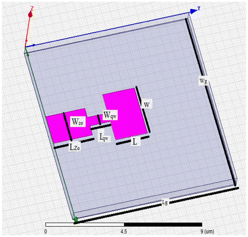
Transmission line model represents RMPA as two slots of width, w (26.5 mm) and height, h (3.2 mm) separated by transmission line of length, l (26.2 mm). Thus, it is a non-homogeneous structure made up of two dielectrics i.e. substrate and air (Balanis, Citation1999).Ground plane has length, l (73 mm) and width, wg (65.6 mm).
Microstrip feed using quarter wave transformer has been used for feeding the antenna as calculated from Equation (1). The input impedance is taken at the base of microstrip feed line and is referred to 50 Ω i.e. Z0.(1)
(1)
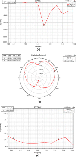
where the Wqw (4.95 mm) and Lqw (9.75 mm) represent the width and length of the quarter wave transformer as calculated from Zqw i.e. impedance of quarter wave transformer using TX line software by AWR. The resonant frequency of the RMPA designed for U–T shape MTM is 7 GHz with RT Duroid (εr = 2.33) as substrate is shown in Figure .
Figure shows the simulation results where S11 is return loss or reflection coefficient.
Simulation results have been shown in Table .
Table 1. Simulation results of RMPA at 7 GHz
It can be seen that S11 is crossing 10 dB line and voltage standing wave ratio is less than 2. Bandwidth is 761 MHz, which is range of frequencies with VSWR < 2.
This has applications in C-band e.g. satellite communications etc.
3. Novel U–T-shaped metamaterial
A novel U–T shape metamaterial is designed. It behaves as DNG i.e. double negative group i.e. having negative permeability and permittivity over same frequency region (Benosman & Hacene, Citation2012; Withayachumnankul & Abbott, Citation2009). The parameter retrieval is done using Nicholson Ross Weir method (Ionescu & Kovaci, Citation2011).
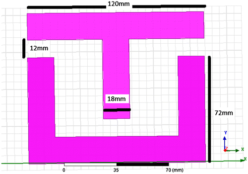
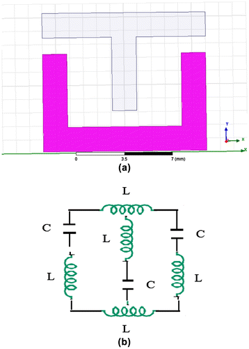
It is constructionally very simple, consists of a U- and T-shaped segments with RT Duroid substrate (Barasara, Prajapati, & Dethalia, Citation2012; Benosman & Hacene, Citation2012). It is designed in such a way that the inclusions are much smaller than the operating wavelength (Parul & De, Citation2013). Such structures can be denoted by quasi-static equivalent LC circuit. Unit cell formed in HFSS is shown in Figure with constructional details.
Ansoft HFSS has been used to simulate the unit cell designed in Figure having metamaterial in the dielectric substrate bounded by box on either side having air as material and radiation boundary.
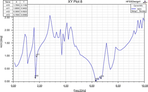
It can be observed as in Figure that near zero refraction is observed around 7 GHz.
4. Mathematical proof
U–T (Dhouibi & Lustrac,Citation2013) shape MTM has magnetic and electric properties because of internal inductances and capacitances. It can be simplified in terms of combinations of parallel RC and series RL. Using transmission line theory (quasi-static regime), we can draw its equivalent circuit as in Figure (a) and (b).
The L is the inductance per unit length of the loop and C is the capacitances of the gap.
The expressions for L and C are given by Equations (2) and (3) as below (Benosman & Hacene, Citation2012):(2)
(2)
where μ = μ0 is the vacuum permeability.(3)
(3)
where C is the expression for calculating parallel plate capacitance.
Neglecting high frequency losses, magnetic resonance frequency are given by Equation (4).
(4)
(4)
Thus, resonance frequency is found out to be 6 GHz. However, using simulational study of MTM in Ansoft HFSS, resonance frequency has been found out to be 7 GHz. Thus, net error between simulational and analytical study is around 1%.
5. Antenna parameter optimization
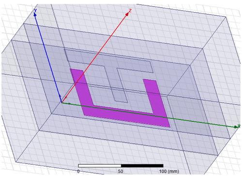
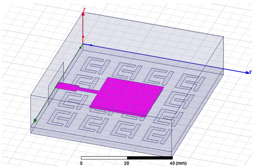
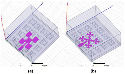
Antenna is characterized by different parameters e.g. gain, bandwidth, VSWR, 3 dB beamwidth in E, H plane, and return loss. Parameter optimization is done by embedding in the middle of the substrate U–T metamaterial in array of 4 × 4 elements spaced at dx = 4.6 and dy = 3.5 mm and centre of the array coincides with the centre of the antenna substrate just below the patch as shown in Figure .
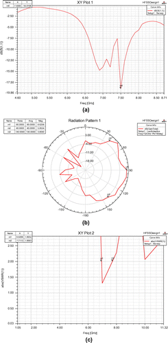
Simulation results for MTM array inside RMPA substrate are shown in Figure .
Table gives the obtained simulated values of parameters and comparison of four segment SRR MTM array RMPA with RMPA without MTM.
Table 2. Simulation and comparison results of U–T shape MTM array embedded in RMPA substrate
6. Fractalization approach
The term fractal, meaning “self-similar”, was first coined by Mandelbrot in 1970. Since then, many sizes and shapes are used for the designing of the fractal antenna, like Cantor (1872), Peano (1890), Hilbert (1891), Helge von Koch (1904), Sierpinski (1916), Gaston Julia (1918), for applications in wireless communication (Barasara et al., Citation2012; Best & Morrow, Citation2002; Cohen, Citation1997; Singh, Grewal, & Saxena, Citation2009; Vinoy, Citation2002).
Thus, a fractal can fill the space occupied by the antenna in a more effective manner than the traditional Euclidean antenna. The benefit is that the increased space-filling ability of the fractal loop means that more electrical length can be fitted into a smaller physical area. The increased electrical length leads to a lower resonant frequency, which effectively miniaturizes the antenna (Coher, Citation1995).
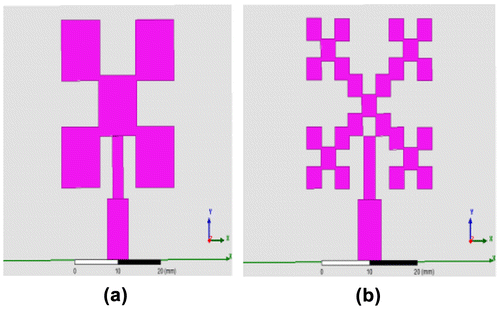
In Figure (a), five fractals of dimensions 9.1 mm × 9.5 mm are placed to form first order fractal (Islam, Faruque, & Islam, Citation2014) antenna and in Figure (b), each unit is further divided using the same iterative method to form second order fractal antenna.
The metamaterial as array of 4 × 4 has been placed in the middle of the substrate such that the centre of metamaterial coincides with the centre of the patch for both first and second order fractal as shown in Figure .
Results obtained have been tabulated in Table .
Table 3. Fractal metamaterial antenna
Thus, using fractal metamaterial antenna of second order iterative mathematics, we can miniaturize the antenna by 75% along with improvement in bandwidth. The increase in bandwidth is achieved due to decrease in impedance of the substrate. This is a boon in today’s wireless communication, where the requirement is very sharp resonance antenna with smaller physical dimensions.
7. Results and discussion
Upon designing and analysing proposed MTM inside RMPA substrate, we obtain results as in Table . It can be seen that bandwidth increases by 120 MHz with U–T shape MTM, directivity increases by 24% and gain increases by 18%. However, the coherence between equivalent circuit analysis using parametric study and FEM technique in HFSS has been observed which nearly about 1% is. Thus, using fractal metamaterial antenna of first and second order iterative mathematics, we can miniaturize the antenna by 58 and 75% along with improvement in bandwidth.
The proposed technology is suitable for C-band applications. However, to extend the applications to higher frequencies, the dimensions of the antenna and metamaterial need to be scaled to the extent the fabrication is possible. Also, the fractalization of antenna follows iterations e.g. first order, second order etc. Each order increases the effective length of the patch antenna, but decreases the dimensions to be fabricated. So, fractalization approach is limited to the extent the dimensions are physically realizable.
Cover image
Source: Author
Additional information
Funding
Notes on contributors
Parul Dawar
Parul Dawar is assistant professor in Guru Tegh Bahadur Institute of Technology, GGSIPU, Delhi, India. Her research interests include electro-magnetic field waves, optical communications and microwave electronics. She has authored two books titled Electromagnetic Field Theory and Concepts in Electromagnetic Field Theory under Katson publications. She has attended and published various papers in National and International Conferences.
N.S. Raghava
N.S. Raghava is working as associate professor in Electronics and Communication Engineering Department in Delhi Technological University, India. His area of specialization is Antenna and Propagation, Microwave Engineering, Digital Communication, Wireless comm., Cloud Computing, Information Security.
Asok De
Asok De is, at present, professor in Electronics and Communication Engineering, Delhi College of Engineering and on lien, working as Director of NIT Patna and NIT Durgapur, India. His field of interest is antennas, Numerical techniques in Electromagnetic, Transmission lines etc. He has published many research papers in reputed Journals.
References
- Balanis, C. A. (1999). Antenna theory. New York, NY: Wiley.
- Barasara, D. J., Prajapati, J. C., & Dethalia, A. M. (2012). Multi frequency fractal antenna. International Journal of Scientific & Engineering Research, 3, 1–3. ISSN .
- Benosman, H., & Hacene, N. B. (2012). Design and simulation of double “S” shaped metamaterial. International Journal of Computer Science Issues, 9, 534–537. ISSN (Online): .
- Best, S. R., & Morrow, J. D. (2002). The effectiveness of space-filling fractal geometry in lowering resonant frequency. IEEE Antennas and Wireless Propagation Letters, 1, 112–115.10.1109/LAWP.2002.806050
- Chen, H., Ran, L., Huangfu, J., & Zhang, X. (2004). Left-handed materials composed of only S-shaped resonator. Physical Review E, 70, 940–942.
- Cohen, N. (1997). Fractal antenna applications in wireless telecommunications. In Professional Program Proceedings of Electronics Industries Forum of New England (pp. 43–49). IEEE.
- Coher, N. (1995). Fractal antenna part-1: Introduction and the fractal quad. Communications Quaterly, 7–22.
- Dhouibi, B., & Lustrac, P. (2013). Analysis of a subwavelength Z-shaped metamaterial. IOP Conference Series: Materials Science and Engineering, 44, 012011.
- Ekmekci, E., & Sayan, G. T. (2007, December). Investigation of effective permittivity and permeability for a novel V-shaped metamaterial using S-parameters. In Proceedings of the 5th International Conference on Electrical and Electronics Engineering (pp. 5–9). Bursa.
- Gianvittorio, J. P., & Rahmat-Samii, Y. (2002). Fractal antennas: A novel antenna miniaturization technique, and applications. IEEE Antennas and Propagation Magazine, 44, 20–36.10.1109/74.997888
- Ionescu, D., & Kovaci, M. (2011). About the negative permittivity of some metamaterial composites–simulational study. In IEEE 17th International Symposium for Design and Technology in Electronic Packaging (SIITME) (pp. 197–200). Timisoara. 10.1109/SIITME.2011.6102717
- Islam, S. S., Faruque, M. R. I., & Islam, M. T. (2014). The design and analysis of a novel split-H-shaped metamaterial for multi-band microwave applications. Materials, 7, 4994–5011.10.3390/ma7074994
- Mahatthanajatuphat, C., Saleekaw, S., & Akkaraekthalin, P. (2009). A rhombic patch monopole antenna with modified Minkowski fractal geometry for UMTS, WLAN, and mobile WIMAX application. Progress in Electromagnetics Research, 89, 57–74.10.2528/PIER08111907
- Mallik, A., Kundu, A. S., & Goni, M. O. (2013). Design of a novel two-rectangular U-shaped double negative metamaterial. In Proceedings of the International Conference on Informatics, Electronics & Vision (ICIEV) (pp. 17–18). Dhaka.
- Parul, D., & De, A. (2013, September 20–22). Bandwidth enhancement of RMPA using ENG metamaterials at THz. In International Conference on Computer Advances in Engineering and Technology (ICCCT-2013) held at MotiLal Nehru National Institute of Technology (pp. 11–16). Allahabad: IEEE Xplore. ISBN: 978-1-4799-1569-9.
- Pozar, D. M. (1992). Microstrip antennas. Proceedings of the IEEE, 80, 79–91.10.1109/5.119568
- Schantz, H. (2005). The art and science of ultra wideband antennas. Norwood, MA: Artech House.
- Singh, K., Grewal, V., & Saxena, R. (2009). Fractal antennas, a novel miniaturization technique for wireless communications. International Journal of Recent Trends in Engineering, 2, 172–176.
- Vinoy, K. J. (2002). Fractal shaped antenna elements for wide and multi-band wireless applications (thesis). Pennsylvania State University, Pennsylvania, PA.
- Withayachumnankul, W., & Abbott, D. (2009). Metamaterials in the terahertz regime. IEEE Photonics Journal, 1, 99–118.10.1109/JPHOT.2009.2026288

