 ?Mathematical formulae have been encoded as MathML and are displayed in this HTML version using MathJax in order to improve their display. Uncheck the box to turn MathJax off. This feature requires Javascript. Click on a formula to zoom.
Abstract
High-quality vertically aligned carbon nanotubes (VACNTs) were synthesised using ferrocene-chicken oil mixture utilising a thermal chemical vapour deposition (TCVD) method. Reaction parameters including vaporisation temperature, catalyst concentration and synthesis time were examined for the first time to investigate their influence on the growth of VACNTs. Analysis via field emission scanning electron microscopy and micro-Raman spectroscopy revealed that the growth rate, diameter and crystallinity of VACNTs depend on the varied synthesis parameters. Vaporisation temperature of 570°C, catalyst concentration of 5.33 wt% and synthesis time of 60 min were considered as optimum parameters for the production of VACNTs from waste chicken fat. These parameters are able to produce VACNTs with small diameters in the range of 15–30 nm and good quality (ID/IG ~ 0.39 and purity ~76%) which were comparable to those synthesised using conventional carbon precursor. The low turn on and threshold fields of VACNTs synthesised using optimum parameters indicated that the VACNTs synthesised using waste chicken fat are good candidate for field electron emitter. The result of this study therefore can be used to optimise the growth and production of VACNTs from waste chicken fat in a large scale for field emission application.
Public Interest Statement
Chicken fat is a free waste material that can be obtained from the wet market and slaughterhouse. In this project, the waste chicken fat was used to produce an exceptional material called carbon nanotube. The selection of waste chicken fat as starting material is due to its high carbon content and zero cost. The effort of utilising the waste chicken fat has reduced the production cost of carbon nanotubes and also reduced the environmental impact of the improper disposal of waste chicken fat. This article studies the effect of important parameters including temperature, catalyst and time towards the production of carbon nanotubes. The results of this study demonstrate that the production of carbon nanotubes from waste chicken fat can potentially be controlled by selection of synthesis parameters.
1. Introduction
Thermal chemical vapour deposition (TCVD) method is the most commonly used method for synthesis of carbon nanotubes (CNTs). This method represents simplest preparation set-up where the CNTs can be grown under mild synthesis condition (ambient pressure and low growth temperature), simple facility and low cost as the use of high-quality substrate and chemicals are not required (Zhang, Huang, Qian, Zhang, & Wei, Citation2006). This method is also considered to be an economic and practical process for large scale production of high purity CNTs (Prasek et al., Citation2011). The use of TCVD with floating catalyst method is one of the most popular methods for synthesising dense and aligned forms of CNTs (Liu, Lam, Fan, Tran, & Duong, Citation2015; Prasek et al., Citation2011). Using floating catalyst method, the catalyst would densely distribute on the surface of the substrate, hence the growth direction of the CNTs would be only in vertical direction since no more space in other direction was available for them to grow. The overcrowding of the CNTs in the array forces the nanotubes to continuously grow in vertical direction until being terminated (Deck & Vecchio, Citation1995), producing vertically aligned CNTs (VACNTs).
In certain application such as for field emitters and displays, VACNTs is a key component (In, Grigoropoulos, Chernov, & Noy, Citation2011). The VACNTs have high capability to provide excellent field emission properties by producing high current densities under low operating voltages (Seah, Chai, & Mohamed, Citation2011). To achieve high density and good alignment VACNTs produced by TCVD method, systematic optimisations on the critical parameters are essential and needed. to take into account. Previous studies found that the density and alignment of the CNTs are closely related to the growth temperature, catalyst concentration, feed rate and period of growth (Azmina, Suriani, Falina, Salina, & Rusop, Citation2012; Cao et al., Citation2014; Guzmán de Villoria, Hart, & Wardle, Citation2011; Paradise & Goswami, Citation2007; Park et al., Citation2014). In addition, a controllable, cost-effective and highly adjustable synthesis procedures are necessary for the development of large scale applications.
The utilisation of waste material as a carbon precursor for the production of VACNTs catches researchers’ attention due to economical and environmental concern. The use of waste materials as carbon precursor helps to reduce the amount of waste generated and convert it into more useful and high-value product i.e. CNTs. Suriani, Md. Nor and Rusop (Citation2010) demonstrated that waste cooking palm oil can be utilised as the carbon precursor to synthesise the VACNTs with the aid of ferrocene as catalyst. Although waste cooking palm oil shows high potential as carbon precursor, but in terms of supply chains, the waste cooking palm oil is only available from household kitchen and local restaurants (Chakraborty, Gupta, & Chowdhury, Citation2014). The limitation in supply chain is in contrast to waste chicken fats that have more centralised supply chain as they are in abundance at slaughterhouses and poultry farms. With high carbon content, low C:H ratio, low cost, environmental impact (Dalila, Suriani, Rosmi, Rosazley, et al., Citation2014; Suriani et al., Citation2013; Suriani, Dalila, Mohamed, Isa, et al., Citation2015) and good supply chain, the use of waste chicken fats as a source of carbon for the production of VACNTs should be explored. Therefore, extensive and continuous efforts are greatly needed particularly to produce VACNTs from waste chicken fats.
To the best of our knowledge, this is the first report on entire parametric study of the synthesis parameters affecting the growth of VACNTs from waste chicken fats using TCVD and ferrocene catalyst. These parameters include the vaporisation temperature, catalyst concentration and growth duration. Samples collected after reaction are characterised using field emission scanning electron microscopy (FESEM), energy dispersive X-ray (EDX), micro-Raman spectroscopy, thermogravimetric analyser (TGA), high-resolution transmission electron microscopy (HRTEM) and field electron emission (FEE). The results indicate that the growth of VACNTs from waste chicken fat can potentially be controlled by the selection of synthesis parameters.
2. Materials and methods
The optimisation of the oil extracted from waste chicken fats that initially carried out shows that the mixture of chopped fats and skins heated in an oven for 30 min was a practical preparation of chicken oil as carbon precursor (Nor Dalila, Citation2016). This method was simple, economical, did not involve much work and proven in producing small diameter and high-quality VACNTs (Nor Dalila, Citation2016). Ferrocene was mixed directly with the extracted oil at the range of 1.33–10.33 wt% and stirred thoroughly for 30 minutes. The dual stage TCVD furnace used in this study consists of 10 cm heating element in each stage and capable of heating the furnace up to 1,100°C with temperature stability of ±1°C. About 6 ml of the mixture was then introduced into the vaporisation furnace of a TCVD system and synthesis was carried out at 800°C (Dalila, Suriani, Rosmi, Azmina, et al., Citation2014; Shamsudin, Suriani, Abdullah, Yahya, & Rusop, Citation2013). The TGA analysis of the chicken oil (Suriani et al., Citation2013) shows that the oil fully decomposed at 470°C. With the presence of ferrocene as catalyst in the ferrocene–chicken oil mixture, this temperature would decrease. Therefore, the range of vaporisation temperature in this study covers the lower and upper range of the chicken oil’s vaporisation temperature i.e. 370–770°C. The synthesis time was varied from 30 to 90 min with the increment of 10 min. The effects of short synthesis time were also studied where the synthesis time is decreased down to 5 min. Other synthesis process was similar to that previously reported (Azmina, Suriani, Salina, et al., Citation2012; Suriani et al., Citation2013; Suriani, Azira, Nik, Md. Nor, & Rusop, Citation2009; Suriani, Dalila, Mohamed, Soga, & Tanemura, Citation2015). The product deposited on silicon substrates was collected and analysed by FESEM (Hitachi SU8020), EDX (Hitachi SU8020), micro-Raman spectroscopy (Renishaw InVia microRaman System) and TGA (Perkin-Elmer Pyris 1). HRTEM (JOEL JEM 2100F) was employed to study the internal structures of selected samples of VACNTs. The FEE measurements were performed at 3 x 10⁻⁵ Pa in a diode configuration with the area of the electron emission of 0.1 cm2 and the separation between electrodes was 100 μm (Suriani, Dalila, et al., Citation2016; Suriani, Safitri, et al., Citation2016).
3. Results and discussions
3.1. Effect of vaporisation temperature
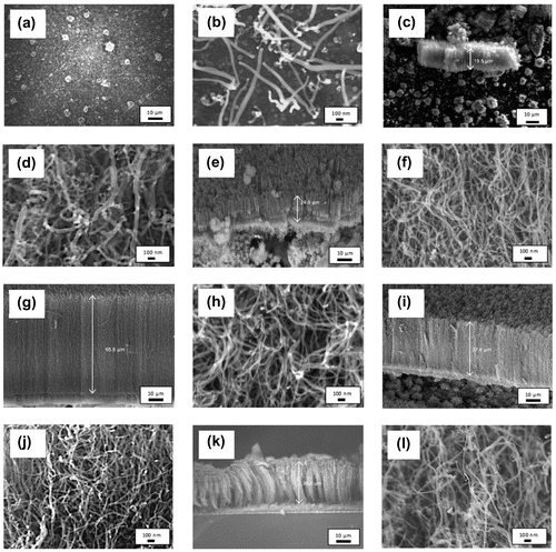
In order to study the effect of vaporisation temperature on the growth of VACNTs, the synthesis temperature was kept constant at 800°C and the synthesis time was set to 60 min. The catalyst concentration was fixed to 5.33 wt% throughout the experiment. The FESEM images of carbon structures synthesised at low precursor vaporisation temperature range of 370–420°C were shown in Figure . It was observed in Figure (a) that no CNT was formed. Instead, the substrate was covered with flake-like carbonaceous structures. When the vaporisation temperature increased to 420°C (Figure (b)), it can be seen that the substrate was covered with small amount of CNTs and the carbon nanospheres with the diameters of 19.8–37.7 and 115.0 nm, respectively. The poor-quality carbon structures synthesised using the low temperature range of 370–420°C were resulting from the insufficient heat supplied in order to completely vaporise the precursor–catalyst mixture in the vaporisation furnace. This is supported by the TGA result (Suriani et al., Citation2013) where only 1.0 and 6.8% of the chicken oil were vaporised when the oil heated at 370 and 420°C, respectively. Partial amount of the catalyst–carbon precursor mixture was vaporised resulting in low carbon concentration to take part in the growth process. Therefore, only low quality in small quantity carbon products was produced.
Figure 1. FESEM images of CNTs synthesised at precursor vaporisation temperatures of (a) 370, (b) 420, (c)–(d) 470, (e)–(f) 520, (g)–(h) 570, (i)–(j) 670 and (k)–(l) 770°C at different magnification.
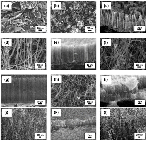
Although the TGA analysis of chicken oil shows that the oil fully decomposed at 470°C, the increase in vaporisation temperature from 100 to 570°C was found to produce even better quality VACNTs. Then, the temperature of 570°C was reduced to 520°C in order to investigate whether this lower temperature is able to produce the same quality of VACNTs as produced at the temperature of 570°C. The FESEM images of VACNTs synthesised with vaporisation temperature of 470–570°C are shown in Figure (c)–(h). As vaporisation temperature increased from 470 to 570°C, it was found that the length and hence the growth rate of the VACNTs increased. The average growth rate of 470, 520 and 570°C sample was 0.72, 0.79 and 1.09 μm min−1, respectively. Meanwhile, the diameter of the VACNTs was found to be smaller and nearly uniform as the vaporisation increased from 470 to 570°C. Smallest and nearly uniform diameters of 18.1–31.2 nm were observed in the sample synthesised with vaporisation temperature of 570°C. This sample also has cleanest nanotubes array as compared to other VACNTs samples, where less carbonaceous structure formed alongside the CNTs. A uniform orientation and nanotubes distribution were also observed in this sample which led to better laterally aligned CNTs than other samples.
The FESEM images of the CNTs synthesised with vaporisation temperature of 670 and 770°C are shown in Figure (i)–(l). VACNTs with shorter length were observed as compared to the VACNTs synthesised with vaporisation temperature of 570°C. The alignment of the CNTs was observed to be poor in both samples and considered as quasi-aligned. This was due to the short length of the CNTs that restricted the tubes to attain dense proximity and intermingle (Morjan et al., Citation2004). As the vaporisation temperature applied increased to 670 and 770°C, the growth rate was found to be reduced to 0.13 and 0.11 μm min−1, respectively. Meanwhile, the diameter of the CNTs became larger (23.8–41.5 and 29.5–75.1 nm for 660 and 770°C sample, respectively). The reduction in the growth rate and larger diameter were due to the excessive energy supplied to the precursor during vaporisation process. This has increased the rate of hydrocarbon particles transported to the silicon substrates. High-concentration hydrocarbon including hydrocarbon radicals would deposit on the surface of the catalyst. The carbon particles encapsulate the catalyst causing reduction in catalytic activity and quicker deactivation and finally termination of the growth of CNTs (Lee, Kim, & Lee, Citation2010; Yamada et al., Citation2008).
The micro-Raman spectra for the CNTs synthesised at different vaporisation temperatures are shown in Figure . Three prominent peaks D, G and G′ that appeared in the range of 1,344.7–1,370.6, 1,576.1–1,581.9 and 2,697.8–2,709.4 cm−1, respectively, were observed in all samples. The D peak corresponds to the defects that are associated with the vacancies and the presence of other carbonaceous impurities, while the G and 2D peaks represent the splitting of the E2g stretching mode for the graphite and overtone of the D band, respectively (Zobir et al., Citation2012). A small shift of D, G and G′ peaks as well as variation in intensities and FWHM shown in Table indicate different crystallinity of the CNTs produced. A clear trend was observed in Table in term of the ID/IG ratio. As vaporisation increased from 370 to 570°C, the ID/IG ratio was found to be decreased with following value: 0.73, 0.66, 0.60, 0.52 and 0.39 for the sample of 370, 420, 470, 520 and 570°C, respectively. This trend indicates the improvement of crystallinity of CNTs as the vaporisation temperature increases up to 570°C. However, above 570°C, the ID/IG ratio increased to 0.54 and 0.67 for the sample of 670 and 770°C, respectively.
Figure 2. Micro-Raman spectra of the samples synthesised at different vaporisation temperatures of 370–770°C with enlarged spectrum of 2D peak.
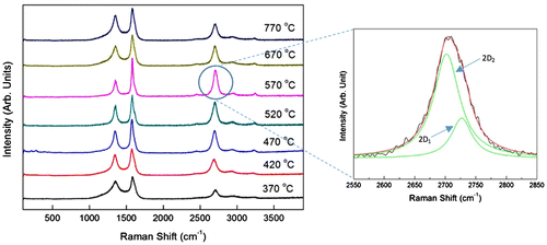
Table 1. The ID/IG ratio of the CNTs samples synthesised at different vaporisation temperatures of 370–770°C
These results were in agreement with the G′ peak’s width where narrowest width was observed from the sample synthesised using vaporisation temperature of 570°C. The samples with vaporisation temperature below 570°C as well as beyond this temperature were found to have larger G′ width, which indicates higher defects of the CNTs produces. The low crystallinity CNTs produced at low vaporisation temperature was due to insufficient energy supplied which led to low concentration of carbon particles vaporised and took part in the formation of CNTs. Meanwhile, the excessive energy at high vaporisation temperature produces abundant hydrocarbon particles on the surface of catalyst. These carbon particles encapsulate the catalyst causing reduction in catalytic activity which in turn produces higher disorder structure in CNTs.
The curve fit of the G′ peaks of all samples was done using Lorentzian distribution. The G′ peak deconvoluted into two peaks of 2D1 and 2D2 that appear around 2,669.7–2,703.9 cm−1 and 2,694.5–2,729.2 cm−1, respectively (Table ). Since G′ peak is sensitive to 3-D graphene-stacking layer (Ferrari et al., Citation2006), the ratio of intensity I2D1/I2D2 as well as the difference (2D2–2D1) in the deconvulated peaks indicates the quality of stacked graphene layers. The I2D1/I2D2 ratio calculated gave lower values of 0.10–0.24 for the VACNTs synthesised at vaporisation temperature of 520–770°C, which indicates that well-aligned 3D graphene stacking layer was formed at high vaporisation temperature range. Although the sample synthesised at vaporisation temperature of 370°C also has low I2D1/I2D2 ratio, the difference between the 2D2–2D1 wave number is very small (only 4 cm−1) as compared to sample synthesised at vaporisation temperature of 520–770°C (2D2–2D1 between 15.4 and 31.3 cm−1). This finding supports the FESEM image of the flake-like carbonaceous carbon structure synthesis at vaporisation temperature of 370°C.
Table 2. The curve fitting results for second-order Raman peak using the Lorentzian distribution function
3.2. The effect of catalyst concentration
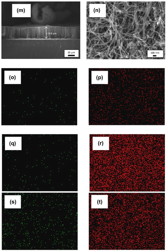
In order to study the effect of catalyst concentration on the growth of VACNTs, the synthesis and vaporisation temperatures were kept constant at 800 and 570°C, respectively, while the synthesis time was set to 60 min. The FESEM image in Figure (a) shows that no VACNT was formed when only 1.33 wt% catalyst was used. Instead, a small yield of CNTs with diameter of 21.2–70.7 nm was produced (Figure (b)). The growth of VACNTs at very low ferrocene concentration was not possible due to low yield of nanotubes produced. When the concentration of the catalyst increases to 3.33 wt%, VACNTs with the length of 19.5 μm were produced, giving the growth rate of 0.33 μm min−1 (Figure (c)–(d)). The growth rate was then increased to 0.41 μm min−1 when 4.33 wt% catalyst was used (Figure (e)–(f)). VACNTs with length of 65.5 μm were produced giving the maximum growth rate of 1.09 μm min−1 as the catalyst concentration increased to 5.33 wt% (Figure (g)–(h)).
Figure 3. FESEM images of the sample synthesised at ferrocene concentration of (a)–(b) 1.33, (c)–(d) 3.33, (e)–(f) 4.33, (g)–(h) 5.33, (i)–(j) 6.33, (k)–(l) 7.33, and (m)–(n) 10.33 wt% at different magnification. EDX maps of Fe catalyst (green) and carbon (red) of (o)–(p) 1.33, (q)–(r) 5.33, and (s)–(t) 10.33 wt%.
Apart from the increment of VACNTs’ growth rate, the diameters of the CNTs were found to be smaller and more uniform as the concentration of catalyst increased from 1.33 to 5.33 wt%. Largest diameters were recorded in 1.33 wt% sample with diameters of 30.2–70.7 nm, while the samples of 4.33 and 5.33 wt% have nearly uniform diameters as shown in Figure (f) and (h), respectively. The amount of impurities produced was also found to be reduced where cleanest nanotubes array was observed in the sample of 5.33 wt%. The changes in growth rate, diameter and amount of impurities at low range of catalyst concentration (1.33–3.33 wt%) were due to the insufficient amount of Fe particles producing imbalance carbon to catalyst ratio (Asli, Shamsudin, Suriani, Rusop, & Abdullah, Citation2013). The small amount of Fe catalyst was unable to decompose the excessive amount of carbon atoms and hence would be encapsulated by the carbon atoms and become inactive (Stadermann et al., Citation2009). Hence, low growth rate, big nanotubes and high amount of carbon impurities were produced.
As the catalyst concentration further increased to 6.33, 7.33 and 10.33 wt% (Figure (i)–(n)), the growth rate decreases to 0.63, 0.61 and 0.33 μm min−1, respectively. Meanwhile, the diameters of CNTs increase as the catalyst concentration increases. The low growth rate and bigger size of CNTs at high catalyst concentration range (6.33–10.33 wt%) were due to the excessive amount of ferrocene that decomposed into Fe clusters deposited on the silicon substrate. These clusters were then agglomerated and formed larger clusters hence producing bigger diameter of CNTs. Moreover, this large size clusters with low surface-to-volume ratio have weak catalytic effect and hence promoting a poor growth of VACNTs (Li et al., Citation2010). The diameters, length and growth rates of the CNTs synthesised using catalyst concentration of 1.33–10.33 wt% are tabulated in Table as comparison.
Table 3. Diameter, length and the growth rate of the CNTs synthesised using different catalyst concentration of 1.33–10.33 wt%
Figure (o)–(t) shows EDX maps for the CNTs synthesised at lowest, medium and highest catalyst concentration of 1.33, 5.33 and 10.33 wt%, respectively. These three values of concentration were chosen in order to investigate the catalyst distribution and relate with carbon production and amount of catalyst being dissolved in the carbon precursor. From EDX maps of Fe and carbon, it is seen that lowest catalyst concentration of 1.33 wt% leads to lowest carbon density (Figure (o)–(p)). The highest carbon density with tolerable Fe density was detected at catalyst concentration of 5.33 wt% (Figure (q)–(r)) which then considered as optimised parameter. Meanwhile, the highest catalyst concentration of 10.33 wt% (Figure (s)–(t)) shows lower carbon density as compared to 5.33 wt%. This was associated with the contamination of metal catalyst hindering the high production of carbon.
The micro-Raman spectra of the CNTs synthesised using catalyst concentration of 1.33–10.33 wt% are shown in Figure . The D peaks appear in the range of 1,342.6–1,352.7 cm−1, while the G peaks appear between 1,576.1 and 1,590.4 cm−1 (Table ). It can be seen that the D and G′ peaks are broader at low catalyst concentration of 1.33 wt% indicating higher defect in the sample. The ID/IG ratio calculated shows that the lowest ID/IG ratio of 0.39 was obtained from 5.33 wt% sample. The ID/IG ratio was found to be increased up to 0.96 and 0.89 for the respective sample with 1.33 and 10.33 wt% catalysts. The high value of ID/IG ratio indicates low crystallinity of the sample attributed to the presence of large amount of amorphous carbon and defect in the sample. The poor crystallinity CNTs produced at low catalyst concentration was due to the inadequate amount of catalyst to decompose the high amount of hydrocarbon particles. The catalytic activity of the catalysts was reduced as they were covered by thick layer of carbon atoms (Stadermann et al., Citation2009). On the other hand, at high catalyst concentration, the low crystallinity was due to low catalytic activity of the bigger size catalyst as a result of agglomeration.
Figure 4. Micro-Raman spectra of the sample synthesised using different catalyst concentration of 1.33–10.33 wt%.
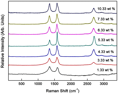
Table 4. The D and G peaks position and the ID/IG ratio of the sample synthesised using catalyst concentration of 1.33–10.33 wt%.
3.3. The effect of synthesis time
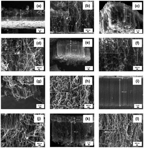
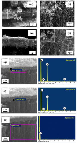
In order to study the effect of synthesis time on the growth of VACNTs, the synthesis and vaporisation temperatures were kept constant at 800 and 570°C, respectively, while the catalyst concentration was fixed to 5.33 wt%. VACNTs were successfully synthesised at synthesis time of 60 min and the quasi-aligned CNTs were grown at other synthesis time of 5–50 and 70–90 min as shown in Figure . A growth rate of 0.57 μm min−1 was recorded for the sample synthesised at 5 min but dropped to 0.46 μm min−1 for the sample synthesised at 30 min. The reduction in the growth rate with the increase in synthesis time was believed due to the secondary array grown on top of the CNTs. This secondary array was in the form of non-tubular, CNTs or mixed structure as shown in the inset of Figure . The samples synthesised at 5, 80 and 90 min in Figure (b), (n), and (p) showed that their secondary arrays were dominated by non-tubular structure, most likely the amorphous carbon or graphite.
Figure 5. FESEM images of the sample synthesised at various synthesis time of (a)–(b) 5, (c)–(d) 30, (e)–(f) 40, (g)–(h) 50, (i)–(j) 60, (k)–(l) 70, (m)–(n) 80, and (o)–(p) 90 min at different magnification. The inset images show the structure of the secondary array. The FESEM images with EDX analysis done on (q) the boundary line; (r) a random point on boundary line; and (s) lower part of the boundary line.
As synthesis time increased to 30 min (Figure (c)–(d)), the amount of non-tubular structure deposited in secondary growth layer reduced and the amount of CNTs structure increased. These changes were then followed with the domination of CNTs structure in the secondary growth layer as the synthesis time increased to 40–70 min. The domination of amorphous carbon in the secondary array at shortest synthesis time speculated to be related with mechanism of the CNTs initial layer array that was based on the bottom growth mechanism. Here, the catalyst particles remain intact with the substrate as the capillary force did not take effect due to short synthesis time. Hence, the decomposition of hydrocarbon particles did not occur as the particles were not able to reach the catalyst due to dense and crowded initial array of CNTs (Saheed, Mohamed, & Burhanudin, Citation2014).
At longest synthesis time, domination of amorphous carbon in secondary array was due to the passivation of the catalyst where the catalysts became inactive at long synthesis time hence hinders the growth of CNTs. The domination of CNTs structure in the secondary growth layer of 40–70 min samples might be catalysed by the catalyst that was brought up to a certain height by capillary force (Tawfick et al., Citation2013). This was supported by the EDX analysis done on the boundary line and at a random point on boundary line of the VACNTs synthesised at 60 min as shown in Figure (q)–(r) and spectrum 1 and 2, respectively. The scan was then performed on the lower part of the boundary (Figure (s)) and spectrum 3. The EDX analyses in Table show the trace of Fe on the boundary line has highest weight percentage (6.84%) followed by at a random point (6.26%). Meanwhile, the Fe distribution at lower part of the boundary has negative weight percentage (−8.89%) which attributed to poor peak-to-background value. This analysis justified that the growth of secondary array was initiated by the raised catalyst.
Table 5. The weight % of element content at different part of VACNTs
It was noted that the diameters of CNTs were affected by the synthesis time. Smallest diameters of 18.1–31.2 nm were detected from the sample synthesised at 60 min while the diameter increased as the synthesis was done below or above 60 min in the range of 19.8–84.1 nm. The diameter and the length of each layer array of the samples synthesised were tabulated in Table . Thickest and cleanest morphology with fewer impurities were also obtained with synthesis time of 60 min. With smallest diameter, cleanest morphology and thickest array obtained, hence 60 min was considered as optimum synthesis time.
Table 6. Diameter, length and the growth rate of the nanotubes synthesised by synthesis time of 5–90 min
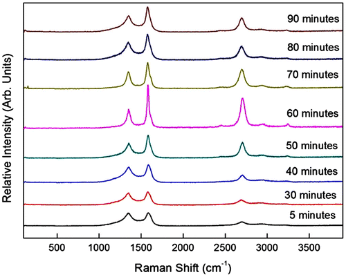
The micro-Raman spectra of the CNTs synthesised by various synthesis times are shown in Figure . The D peaks appeared at 1,336.7.6–1,355.9 cm−1, while the G peaks appear at 1,579.6–1,588.6 cm−1. The sample synthesised at 60 min possessed narrowest D and G peaks of 54.5 and 31.6 cm−1, respectively. The G peaks were broader for the samples synthesised below and above 60 min where broader G peak indicates higher disorder (Ferrari, Citation2007). The disappearance of the G′ peak was also related to the sample disorder (Schünemann et al., Citation2011). The G′ peaks disappeared as the synthesis time reduced to 5 min and increased to 90 min indicating an increment in disorder of the samples. These results indicated that the sample synthesised at 60 min had lowest disorder.
This was consistent with the lowest ID/IG value of the 0.39 possessed by the sample synthesised at 60 min. As the synthesis time increased from 5 to 60 min, the ID/IG value decreased from 0.84 to 0.39 which implies an improvement in crystallinity. The ID/IG value was then increased to 0.64 as the synthesis time increased to 70 min. It showed that the crystallinity of the samples was worsened and the defect and disorder were increased for the synthesis time below and above 60 min. The presence of defects that reduced the crystallinity might be due to the catalyst poisoning in which the catalysts became inactive at longer synthesis time. Meanwhile, for shorter synthesis time, the presence of disorder related to the amorphous carbon deposited as second layer array on the CNTs. The position and width of the D, G and G′ peaks and the ID/IG ratio for synthesis times of 5–90 min are tabulated in Table .
Table 7. The D, G and G′ peaks width and the ID/IG ratio of the sample synthesised by synthesis time of 5–90 min
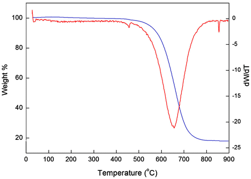
To confirm the purity of the CNTs synthesised using optimum parameters, TGA analysis was performed on the sample i.e. VACNTs synthesised using 6 ml chicken oil. Figure shows a TGA and DTGA graph for the as-grown VACNTs. An initial weight loss of 0.6% was detected at a temperature of 110–250°C due to the decomposition of hydrocarbon impurities. The burning amorphous carbon that occurred from 250 to 550°C constituted approximately 5.2%. It should be noted that 18.0% of the sample weight remained after performing TGA up to 900°C. This result was mainly due to the presence of Fe and other non-volatile constituents found in the VACNTs, which was confirmed previously by EDX analysis (Figure (q)–(s)). From the TGA analysis, the purity of the produced VACNTs was found to be approximately 76.2%. This value demonstrates that high-purity VACNTs can be produced from chicken fat waste-based precursor.
Carbon conversion was calculated based on the mass of collected carbon product and total carbon in the carbon precursor (Das, Dalai, Soltan Mohammadzadeh, & Adjaye, Citation2006). The carbon conversion of chicken oil using optimum parameters (vaporisation temperature of 570°C, ferrocene concentration of 5.33 wt% and synthesis time of 60 min) is presented as follows: The combination of three major compound in chicken oil identified by GCMS (Suriani, Dalila, Mohamed, Isa et al., Citation2015) i.e. C35H70, C18H34O2, C9H14O gives the chemical formula of C62H118O3. The percentage of carbon in the mixture of chicken oil and ferrocene (FeC10H10) is given by following calculation:
The mass of 6 ml chicken oil-ferrocene mixture is 5.507 g. Then, the mass of carbon in the chicken oil-ferrocene mixture given by:
The obtained mass of carbon products (CNTs, amorphous carbon and iron) synthesised using 6 ml chicken oil is 2.318 g. The percentage of carbon conversion is given by:
Therefore, the calculated carbon conversion of chicken oil is 51.94%. The obtained value is comparable to the carbon conversion of camphor oil (61%) (Kumar & Ando, Citation2008), and higher than the carbon conversion of benzene (20%), toluene (31%) and xylene (28%) obtained by Das et al. (Citation2006). This finding approves that the chicken fat is a potential carbon precursor to substitute the fossil-fuel precursor.
Figure (a) displays the typical J-E curve of the VACNTs synthesised at 30 and 60 min. From the curve, the observed turn-on and threshold values were approximately 3.62 and 3.82 V μm−1, which corresponded to current densities of 1 and 10 μA cm−2, respectively, for the sample synthesised at 30 min. Meanwhile, the sample synthesised at 60 min shows lower turn-on and threshold field of 2.66 and 3.18 V μm−1, respectively. The maximum current density was found to be higher for this sample (213 μA cm−2 at applied field of 6.0 V μm−1). The maximum current density of the sample synthesised at 30 min was 123 μA cm−2 at applied field of 4.8 V μm−1 before decreased to 100 μA cm−2 at applied field of 5.0 V μm−1. The lower turn-on and threshold field as well as higher maximum current density possessed by the sample synthesised at 60 min attributed to low defects and good crystallinity of the sample which lead to better FEE performances (Krueger, Citation2010).
Figure 8. (a) Typical J-E curves, (b) F-N plot and HR-TEM images of the VACNTs from waste chicken fats by (c) 30 and (d) 60 min.
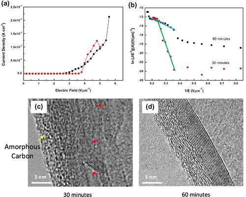
In addition, the sample synthesised at 30 min contained more impurities such as amorphous carbon and non-tubular carbon materials (Figure (d)). The VACNTs synthesised at 60 min look fairly clean and were entangled (Figure (j)). The entangled CNTs secure a good electrical contact all across the CNTs (Kumar, Kakamu, Okazaki, & Ando, Citation2004) and have better long-term stability than the straight CNTs that are easily deflected upon high-field application (Poncharal, Wang, Ugarte, & de Heer, Citation1999). The HR-TEM image in Figure (c) confirms that the VACNTs synthesised at 30 min has thicker layer of amorphous carbon. The tube also contains higher level of defect as indicated by the arrow. Meanwhile, the VACNTs synthesised at 60 min Figure (d) has a clear graphitic layers implying good graphitisation which leads to a better FEE property (Krueger, Citation2010).
Figure (b) shows the F-N plots of the VACNTs synthesised at 30 and 60 min. This plot was obtained according to the typical F-N equation as shown in Equation (1):
(1)
(1)
where J is the current density, E is the applied field and ϕ is the work function (4.8 eV for CNTs (Khazaei & Kawazoe, Citation2007; Martin & Schwoebel, Citation2007)), A and B are constants (A = 1.54 × 10⁻⁶ A eV V−2 and B = 6.83 × 10⁹ eV−3/2 Vm−1) and β is the field enhancement factor which can be obtained using the slope of the linear part of the F-N plot. The F-N plots of both samples are almost linear at high electric field region, in agreement with the F-N mechanism which confirms that the observed current was generated by field emitted electrons. The calculated β for the samples synthesised at 30 and 60 min was found to be 1,012 and 5,130. The obtained values for FEE by the sample synthesised at 60 min are comparable to those obtained by the CNTs synthesised using conventional (Kar et al., Citation2015; Lee et al., Citation2012; Sridhar et al., Citation2014); green (Asli, Shamsudin, Falina, et al., Citation2013) and waste carbon precursors (Falina et al., Citation2012; Suriani et al., Citation2010; Suriani, Alfarisa, et al., Citation2015) as well as the CNTs-metal oxide composite (Guo et al., Citation2013; Suriani, Safitri, et al., Citation2015). The obtained results indicated that the CNTs synthesised using waste chicken fat are a good candidate for field emission application.
4. Conclusions
For the first time, a systematic variation in important VACNT synthesis parameters was performed utilising a TCVD system. The growth rate, diameter and crystallinity of the CNTs were shown to be dependent to all synthesis conditions varied in this study. Vaporisation temperature of carbon precursor, catalyst concentration and synthesis time was monitored. Only flake-like carbon structures were formed at lowest vaporisation temperature of 370°C, while low CNT density was observed at 420°C. Temperature window for dense VACNTs was found to exist between 470 and 570°C with an optimum quality VACNTs was observed at vaporisation temperature of 570°C. Quasi-aligned CNTs were observed at vaporisation temperature higher than optimum temperature. The catalyst concentration was found to be optimal at 5.33 wt%. Lower growth rate, density and crystallinity of VACNTs were observed above and below this concentration. VACNTs were observed between synthesis time of 5–90 min. Secondary growth arrays were also detected in all samples with domination of non-tubular structures such as amorphous and graphite at shortest and longest synthesis time of 5 and 90 min, respectively. Synthesis time of 60 min was found to be optimal due to highest growth rate, small diameters and high crystallinity of VACNTs produced. The carbon conversion of chicken oil using optimum parameters was found to be 54.67%. The good FEE results (low turn-on and threshold field of 2.66 and 3.18 V μm−1, respectively) indicated that the VACNTs synthesised using waste chicken fat are a good candidate for field emission application.
Funding
This work was financially supported by the Kurita Water and Environment Foundation Grant [grant number 2015-0151-102-11]; the Fundamental Research Grant Scheme [grant number 2015-0154-102-02]; the Prototype Development Research Grant Scheme [grant number 2013-0097-102-32]; the National Nanotechnology Directorate Division Research Grant [grant number 2014-0015-102-03]; the MARA Innovation & Research Grant Scheme [grant number 2016-0006-101-20]; UPSI and NIT for the financial support and access to facilities for this work.
Additional information
Notes on contributors
A.B. Suriani
A.B. Suriani is an associate professor at Department of Physics, Universiti Pendidikan Sultan Idris, Perak, Malaysia. Her research is concerned on nanomaterials, with special interest in carbon-based materials including graphene, carbon nanotubes and their applications in electronic devices. She is the author of more than 50 papers in reputed journals. She has received various research grants, among them are from Kurita Water and Environment Foundation, Japan, Malaysia Toray Science Foundation, Ministry of Higher Education of Malaysia and Ministry of Science, Technology and Innovation of Malaysia. She was also awarded the L’Oreal Malaysia for Women in Science Fellowship Award 2013.
References
- Asli, N. A., Shamsudin, M. S., Falina, A. N., Azmina, M. S., Suriani, A. B., Rusop, M., & Abdullah, S. (2013). Field electron emission properties of vertically aligned carbon nanotubes deposited on a nanostructured porous silicon template: The hidden role of the hydrocarbon/catalyst ratio. Microelectronic Engineering, 108, 86–92.10.1016/j.mee.2013.02.095
- Asli, N. A., Shamsudin, M. S., Suriani, A. B., Rusop, M., & Abdullah, S. (2013). Effect of the ratio of catalyst to carbon source on the growth of vertically aligned carbon nanotubes on nanostructured porous silicon templates. International Journal of Industrial Chemistry, 4, 1–7.
- Azmina, M. S., Suriani, A. B., Falina, A. N., Salina, M., & Rusop, M. (2012). Temperature effects on the production of carbon nanotubes from palm oil by thermal chemical vapor deposition method. Advanced Materials Research, 364, 359–362.
- Azmina, M. S., Suriani, A. B., Salina, M., Azira, A. A., Dalila, A. R., Asli, N. A., ... Rusop, M. (2012). Variety of bio-hydrocarbon precursors for the synthesis of carbon nanotubes. Nano Hybrids, 2, 43–63.10.4028/www.scientific.net/NH.2
- Cao, T. T., Nguyen, V. C., Ngo, T. T. T., Le, T. L., Nguyen, T. L., Tran, D. L., … Phan, N. M. (2014). Effects of ferrite catalyst concentration and water vapor on growth of vertically aligned carbon nanotube. Advances in Natural Sciences: Nanoscience and Nanotechnology, 5, 1–6.
- Chakraborty, R., Gupta, A. K., & Chowdhury, R. (2014). Conversion of slaughterhouse and poultry farm animal fats and wastes to biodiesel: Parametric sensitivity and fuel quality assessment. Renewable and Sustainable Energy Reviews, 29, 120–134.10.1016/j.rser.2013.08.082
- Dalila, A. R., Suriani, A. B., Rosmi, M. S., Azmina, M. S., Rosazley, R., Supian, F. L., … Rusop, M. (2014). The effect of synthesis temperature on the growth of carbon nanotubes from waste chicken fat precursor. Advanced Materials Research, 832, 798–803.
- Dalila, A. R., Suriani, A. B., Rosmi, M. S., Rosazley, R., Supian, F. L., Rosly, J., & Rusop, M. (2014). Carbon nanotubes: A brief outlook on history, synthesis methods and various bio-hydrocarbon sources. Advanced Materials Research, 832, 792–797.
- Das, N., Dalai, A., Soltan Mohammadzadeh, J. S., & Adjaye, J. (2006). The effect of feedstock and process conditions on the synthesis of high purity CNTs from aromatic hydrocarbons. Carbon, 44, 2236–2245.10.1016/j.carbon.2006.02.040
- Deck, C. P., & Vecchio, K. (1995). Growth mechanism of vapor phase CVD-grown multi-walled carbon nanotubes. Carbon, 43, 2608–2617.
- Falina, A. N., Suriani, A. B., Azmina, M. S., Salina, M., Dalila, A. R., Md Nor, R., & Rusop, M. (2012). Structural characteristics and field electron emission properties of carbon nanotubes synthesized from waste cooking palm oil. Jurnal Teknologi (Sciences and Engineering), 59, 93–97.
- Ferrari, A. C. (2007). Raman spectroscopy of graphene and graphite: Disorder, electron–phonon coupling, doping and nonadiabatic effects. Solid State Communications, 143, 47–57.10.1016/j.ssc.2007.03.052
- Ferrari, A. C., Meyer, J. C., Scardaci, V., Casiraghi, C., Lazzeri, M., Mauri, F., ... Geim, A. K. (2006). Raman spectrum of graphene and graphene layers. Physical Review Letters, 97, 187401.10.1103/PhysRevLett.97.187401
- Guo, F., Ye, Y., Yang, Z., Hong, C., Hu, L., Wu, C., & Guo, T. (2013). The in situ preparation of novel α-Fe2O3 nanorods/CNTs composites and their greatly enhanced field emission properties. Applied Surface Science, 270, 621–626.10.1016/j.apsusc.2013.01.096
- Guzmán de Villoria, R., Hart, A. J., & Wardle, B. L. (2011). Continuous high-yield production of vertically aligned carbon nanotubes on 2D and 3D substrates. ACS Nano, 5, 4850–4857.10.1021/nn2008645
- In, J. B., Grigoropoulos, C. P., Chernov, A. A., & Noy, A. (2011). Growth kinetics of vertically aligned carbon nanotube arrays in clean oxygen-free conditions. ACS Nano, 5, 9602–9610.10.1021/nn2028715
- Kar, R., Sarkar, S. G., Basak, C. B., Patsha, A., Dhara, S., Ghosh, C., ... Patil, D. S. (2015). Effect of substrate heating and microwave attenuation on the catalyst free growth and field emission of carbon nanotubes. Carbon, 94, 256–265.10.1016/j.carbon.2015.07.002
- Khazaei, M., & Kawazoe, Y. (2007). Effects of Cs treatment on field emission properties of capped carbon nanotubes. Surface Science, 601, 1501–1506.10.1016/j.susc.2007.01.009
- Krueger, A. (2010). Carbon materials and nanotechnology. Weinheim: John Wiley & Sons.10.1002/9783527629602
- Kumar, M., & Ando, Y. (2008). Gigas growth of carbon nanotubes. Defence Science Journal, 58, 496–503.10.14429/dsj
- Kumar, M., Kakamu, K., Okazaki, T., & Ando, Y. (2004). Field emission from camphor–pyrolyzed carbon nanotubes. Chemical Physics Letters, 385, 161–165.10.1016/j.cplett.2003.12.064
- Lee, J., Jung, Y., Song, J., Kim, J. S., Lee, G. W., Jeong, H. J., & Jeong, Y. (2012). High-performance field emission from a carbon nanotube carpet. Carbon, 50, 3889–3896.10.1016/j.carbon.2012.04.033
- Lee, D. H., Kim, S. O., & Lee, W. J. (2010). Growth kinetics of wall-number controlled carbon nanotube arrays. The Journal of Physical Chemistry C, 114, 3454–3458.10.1021/jp911629j
- Li, Y., Cui, R., Ding, L., Liu, Y., & Zhou, W., Zhang, Y., ... Liu, J. (2010). How catalysts affect the growth of single-walled carbon nanotubes on substrates. Advanced Materials, 22, 1508–1515.10.1002/adma.200904366
- Liu, P., Lam, A., Fan, Z., Tran, T. Q., & Duong, H. M. (2015). Advanced multifunctional properties of aligned carbon nanotube-epoxy thin film composites. Materials & Design, 87, 600–605.10.1016/j.matdes.2015.08.068
- Martin, G. L., & Schwoebel, P. R. (2007). Field electron emission images of multi-walled carbon nanotubes. Surface Science, 601, 1521–1528.10.1016/j.susc.2007.01.012
- Morjan, R. E., Maltsev, V., Nerushev, O., Yao, Y., Falk, L. K. L., & Campbell, E. E. B. (2004). High growth rates and wall decoration of carbon nanotubes grown by plasma-enhanced chemical vapour deposition. Chemical Physics Letters, 383, 385–390.10.1016/j.cplett.2003.11.063
- Nor Dalila, A. R. (2016). Synthesis of aligned carbon nanotubes from waste chicken fat using thermal chemical vapour deposition method for field emission devices (PhD thesis). Universiti Pendidikan Sultan Idris, Tanjung Malim.
- Paradise, M., & Goswami, T. (2007). Carbon nanotubes–Production and industrial applications. Materials & Design, 28, 1477–1489.10.1016/j.matdes.2006.03.008
- Park, S., Song, W., Kim, Y., Song, I., Kim, S. H., Lee, S. I., ... Park, C. Y. (2014). Effect of growth pressure on the synthesis of vertically aligned carbon nanotubes and their growth termination. Journal of Nanoscience and Nanotechnology, 14, 5216–5220.10.1166/jnn.2014.7751
- Poncharal, P., Wang, Z. L., Ugarte, D., & de Heer, W. A. (1999). Electrostatic deflections and electromechanical resonances of carbon nanotubes. Science, 283, 1513–1516.10.1126/science.283.5407.1513
- Prasek, J., Drbohlavova, J., Chomoucka, J., Hubalek, J., Jasek, O., Adam, V., & Kizek, R. (2011). Methods for carbon nanotubes synthesis—review. Journal of Materials Chemistry, 21, 15872.10.1039/c1jm12254a
- Saheed, M. S. M., Mohamed, N. M., & Burhanudin, Z. A. (2014). Effect of different catalyst deposition technique on aligned multiwalled carbon nanotubes grown by thermal chemical vapor deposition. Journal of Nanomaterials, 2014, 1–11, Article ID: 707301.
- Schünemann, C., Schäffel, F., Bachmatiuk, A., Queitsch, U., Sparing, M., Rellinghaus, B., ... Rümmeli, M. H. (2011). Catalyst poisoning by amorphous carbon during carbon nanotube growth: Fact or fiction? ACS Nano, 5, 8928–8934.10.1021/nn2031066
- Seah, C. M., Chai, S. P., & Mohamed, A. R. (2011). Synthesis of aligned carbon nanotubes. Carbon, 49, 4613–4635.10.1016/j.carbon.2011.06.090
- Shamsudin, M. S., Suriani, A. B., Abdullah, S., Yahya, S. Y. S., & Rusop, M. (2013). Impact of thermal annealing under nitrogen ambient on structural, micro-Raman, and thermogravimetric analyses of camphoric-CNT. Journal of Spectroscopy, 2013, 1–6, Article ID: 167357.
- Sridhar, S., Ge, L., Tiwary, C. S., Hart, A. C., Ozden, S., Kalaga, K., ... Vajtai, R. (2014). Enhanced field emission properties from cnt arrays synthesized on inconel superalloy. ACS Applied Materials & Interfaces, 6, 1986–1991.10.1021/am405026y
- Stadermann, M., Sherlock, S. P., In, J. B., Fornasiero, F., Park, H. G., Artyukhin, A. B., ... Noy, A. (2009). Mechanism and kinetics of growth termination in controlled chemical vapor deposition growth of multiwall carbon nanotube arrays. Nano Letters, 9, 738–744.10.1021/nl803277g
- Suriani, A. B., Alfarisa, S., Mohamed, A., Isa, I. M., Kamari, A., Hashim, N., ... Rusop, M. (2015). Quasi-aligned carbon nanotubes synthesised from waste engine oil. Materials Letters, 139, 220–223.10.1016/j.matlet.2014.10.046
- Suriani, A. B., Azira, A. A., Nik, S. F., & Md. Nor, R., & Rusop, M. (2009). Synthesis of vertically aligned carbon nanotubes using natural palm oil as carbon precursor. Materials Letters, 63, 2704–2706.10.1016/j.matlet.2009.09.048
- Suriani, A. B., Dalila, A. R., Mohamed, A., Isa, I. M., Kamari, A., Hashim, N., ... Tanemura, M. (2015). Synthesis of carbon nanofibres from waste chicken fat for field electron emission applications. Materials Research Bulletin, 70, 524–529.10.1016/j.materresbull.2015.04.068
- Suriani, A. B., Dalila, A. R., Mohamed, A., Mamat, M. H., Malek, M. F., Soga, T., & Tanemura, M. (2016). Fabrication of vertically aligned carbon nanotubes–zinc oxide nanocomposites and their field electron emission enhancement. Materials & Design, 90, 185–195.10.1016/j.matdes.2015.10.051
- Suriani, A. B., Dalila, A. R., Mohamed, A., Mamat, M. H., Salina, M., Rosmi, M. S., ... Rusop, M. (2013). Vertically aligned carbon nanotubes synthesized from waste chicken fat. Materials Letters, 101, 61–64.10.1016/j.matlet.2013.03.075
- Suriani, A. B., Dalila, A. R., Mohamed, A., Soga, T., & Tanemura, M. (2015). Synthesis, structural, and field electron emission properties of quasi-aligned carbon nanotubes from gutter oil. Materials Chemistry and Physics, 165, 1–7.10.1016/j.matchemphys.2015.09.002
- Suriani, A. B., Md. Nor, R., & Rusop, M. (2010). Vertically aligned carbon nanotubes synthesized from waste cooking palm oil. Journal of the Ceramic Society of Japan, 118, 963–968.10.2109/jcersj2.118.963
- Suriani, A. B., Safitri, R. N., Mohamed, A., Alfarisa, S., Isa, I. M., Kamari, A., ... Rusop, M. (2015). Enhanced field electron emission of flower-like zinc oxide on zinc oxide nanorods grown on carbon nanotubes. Materials Letters, 149, 66–69.10.1016/j.matlet.2015.02.115
- Suriani, A. B., Safitri, R. N., Mohamed, A., Alfarisa, S., Malek, M. F., Mamat, M. H., & Ahmad, M. K. (2016). Synthesis and field electron emission properties of waste cooking palm oil-based carbon nanotubes coated on different zinc oxide nanostructures. Journal of Alloys and Compounds, 656, 368–377.10.1016/j.jallcom.2015.09.277
- Tawfick, S., Zhao, Z., Maschmann, M., Brieland-Shoultz, A., & De Volder, M., Baur, J. W., ... Hart, J. A. (2013). Mechanics of capillary forming of aligned carbon nanotube assemblies. Langmuir, 29, 5190–5198.10.1021/la4002219
- Yamada, T., Maigne, A., Yudasaka, M., Mizuno, K., Futaba, D. N., Yumura, M., ... Hata, K. (2008). Revealing the secret of water-assisted carbon nanotube synthesis by microscopic observation of the interaction of water on the catalysts. Nano Letters, 8, 4288–4292.10.1021/nl801981m
- Zhang, Q., Huang, J. Q., Qian, W. Z., Zhang, Y. Y., & Wei, F. (2006). The road for nanomaterials industry: A review of carbon nanotube production, post‐treatment, and bulk applications for composites and energy storage. Small, 9, 1237–1265.
- Zobir, S. A. M., Bakar, S. A., Abdullah, S., Zainal, Z., Sarijo, S. H., & Rusop, M. (2012). Raman spectroscopic study of carbon nanotubes prepared using Fe/ZnO-palm olein-chemical vapour deposition. Journal of Nanomaterials, 2012, 1–6, Article ID: 451473.

