 ?Mathematical formulae have been encoded as MathML and are displayed in this HTML version using MathJax in order to improve their display. Uncheck the box to turn MathJax off. This feature requires Javascript. Click on a formula to zoom.
Abstract
Non-uniform current distributions of proton-exchange membrane fuel cells (PEMFCs) result in unequal utilization of reactants and catalysts in solution. To prevent the degradation of PEMFC, an in situ approach for characterizing PEMFC stacks is needed. In this study, the current distribution of two-cell PEMFC stacks is replicated from measured magnetic flux densities and operating conditions produced by three-dimensional finite element modeling that included electromagnetic field modeling and electrochemical reactions. I–V curves under normal conditions were replicated from electrochemistry and compared to the measured curves, and magnetic flux density distributions were investigated to determine the operating state. From these results, we discuss the potential use of the proposed approach in in situ applications.
Public Interest Statement
The “hydrogen society” is a concept that has gained notoriety in the world. In the near future, an environmentally friendly society might be realized through the production of hydrogen as a renewable energy source. Fuel cells are important in such a society because they are expected to mitigate environmental problems such as the exhaustion of fossil fuels and continuing greenhouse gas emissions. One type of fuel cell, the proton-exchange membrane fuel cell (PEMFC), has a low operating temperature and can be rapidly started, and has found application in cogeneration systems fuel cell vehicles (FCVs). However, the widespread commercialization of PEMFC stacks depends on their reliability and fault diagnosis. Therefore, an in situ measurement approach on PEMFC stacks has been developed. An in situ method provides a means for nondestructive, noninvasive, and on-site measurement. In this article, the magnetic fields produced by PEMFC currents are explored via three-dimensional finite element modeling.
Competing Interests
The authors declare no competing interest.
1. Introduction
In the evaluation of proton-exchange membrane fuel cells (PEMFCs), the magnitude of non-uniform current distribution is often used as an evaluation index. The currents are affected by the reactant flow and relevant operating conditions, such as the stoichiometry, operating temperature, and relative humidity. Non-uniform current distributions can cause an unequal utilization of reactants and catalysts. Therefore, the improvement of the current distribution of PEMFCs is necessary.
Many methods to measure current distribution exist since their initial measurement in PEMFCs in 1998 (Citation1). In one method, a passive network was developed within the PEMFC using segmented bipolar plates (BP) and Hall sensors (Citation2, 3). Later work clarified the relationship between current distribution and operating conditions, using a print circuit board (PCB), segmented BP, and current collector (Citation4). However, these methods modified the components of the PEMFC. In order to measure the current distribution of contained PEMFC stacks, the methods must be nondestructive.
Magnetic sensors have been used for nondestructive measurements of current distribution in PEMFCs (Citation5). The current distribution has been measured in a single cell using simple equipment, without the need for disassembly (Citation6). The current distribution has been converted from the environmental magnetic flux density using three-dimensional finite element method (3DFEM) simulations in a single cell (Citation7). 3DFEM is used also in the analysis of interfacial contact resistance (Citation7) and in 1D membrane-electrode assembly (MEA) models (Citation8). However, these nondestructive methods are difficult to implement in PEMFC stacks. To measure the current distribution in PEMFC stacks, magnetic sensor probes have been inserted in cooling holes (Citation9, 10, Citation14). In these studies, the measured magnetic flux density was converted to current density using the magnetic field response values of the current provided by the manufacturer. As above, the current distribution of the PEMFC was calculated from the magnetic flux density or the chemical reaction.
In this study, we describe a method to measure the magnetic flux density using a combination of magnetic sensor probes and 3DFEM simulation. The measured magnetic flux densities are converted to current densities on the MEA by the 3DFEM, providing a means to estimate the current distribution and unobserved state in PEMFC stacks. I–V curves and the magnetic flux density distribution are then used to determine the operating state using this simulation method. Finally, we compare the simulation and experimental results.
2. Background theory of simulation
2.1. PEMFC currents
The general mass balance for the species k in electrolyte is described by the Nernst–Planck equation given as(1)
(1)
where Nk is the flux of species k [mol/m2 s], which accounts for the diffusion, migration, and convection of charged solute species, ck represents the concentration of the ion [mol/m3], zk is its valence, Dk is the diffusion coefficient [m2/s], um, k is the mobility [s mol/kg], F denotes the Faraday constant factor, ϕkdenotes the electrolyte potential, and u is the velocity vector [m/s]. The net current density can be described using the sum of all species fluxes:(2)
(2)
where iL denotes the current density vector [A/m2] in the electrolyte.
The current distributions assume an electrolyte that conducts current according to Ohm’s law, with a constant conductivity. The rate of the electrochemical reactions can be described by relating the reaction rate to the activation overpotential. For an electrode reaction with index m, the activation overpotential, denoted by nact, is given by the following:(3)
(3)
where Eeq, k denotes the equilibrium potential for reaction with index m.
Electrochemical reactions are described as a function of the overpotential. Several relations for the charge transfer current density and overpotential exist in physics. In this study, the Butler–Volmer equation was used for the anodic reaction,(4)
(4)
where ik, m denotes the local charge transfer current density for reaction m, i0 is the exchange current density, αa is the anodic transfer coefficient, αc is the cathodic transfer coefficient, and R is the universal gas constant. For the cathodic reaction, the Tafel equation was used,(5)
(5)
where Ac is the Tafel slope. The steady rate of electrode reaction never exceeds the rate at which reactants and products can be transported to and from the electrode surface.
In porous electrodes, the sum of all reaction currents appears as a source for the current distribution in the following equation:(6)
(6)
where av, m is the surface area.
By assuming a Nernst diffusion layer at the electrode surface and a first-order dependence between the charge transfer current and the local concentration of a reacting species, the following kinetics expression can be derived:(7)
(7)
where ie [A/m2] is the current density expression in the absence of mass transport limitations for the species and ilim is the limiting current density that corresponds to the maximum transport rate of the species. The derivation of this expression assumes a cathodic reaction.
2.2. Magnetic fields by PEMFC currents
PEMFC stacks consist of MEAs, separators, and current collectors. Therefore, the current of all the components is needed to calculate the magnetic field. The current of the separators and current collectors is calculated by Ohm’s law:(8)
(8)
where σ is the electrical conductivity [S/m] and E is the electrical field intensity. Under static conditions, this intensity is defined by following relationship:(9)
(9)
where V is an electric potential, such as the cell voltage. To handle the PEMFC current, the equations can be generalized to:(10)
(10)
After calculating the current of all the components, the magnetic field is derived by Ampere’s law, the definition of magnetic potential A, and the constitutive relationships(11)
(11)
(12)
(12)
(13)
(13)
where H is the magnetic field intensity and B is the magnetic flux density vector. In this study, the elements of these components of B and the values measured by the magnetic sensors are compared.
2.3. Assumptions of simulation
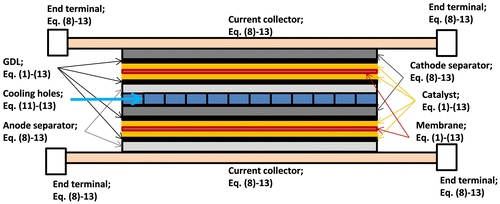
In this study, a computational simulation technique, 3DFEM, was used. It is often used to analyze electric devices such as motors and transformers in electromagnetic fields. Each PEMFC component is modeled using the commercial software simulation package that implements 3DFEM, COMSOL. A schematic of the fuel cell stack and adaptions of the equation number are shown in Figure . The end terminals are connected to the load. The simulation evaluates the electrochemical reactions at MEA, the magnetic flux density distribution at the cooling holes, and the current density distribution.
The simulation conditions are listed in Table . The conductivities used were from a reference source (Citation11). The relative permittivities and permeabilities of the GDL, catalyst, and separator were difficult to measure. Therefore, the average values for graphite (Citation12, 13) were used.
Table 1. Condition of component on the 3DFEM
Finally, the simulation modeled two scenarios, termed normal and fault. The normal scenario assumes steady operation, with the steady voltages during the experiment and uniform current distribution in the simulation. The fault scenario assumes that the voltages varied during the experiment and the local current distribution were zero at the nearest outlet of cell, x = 81 and y = 9. This result and the experiment result of our previous study (Citation14) were compared.
3. Experiment
3.1. PEMFC system and operating conditions
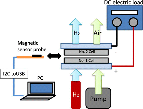
An air-cooled, two-cell PEMFC stack was used in all the experiments. The fuel cell system is shown in Figure . Hydrogen (>99.99% pure) was supplied to the anode without humidification, and dry air was supplied to the cathode. The stack was operated at a constant current using a 160 W DC electric load (TAKASAGO: FK-160L2Z), and the cell voltages were measured using a data logger (HIOKI: 8422-50). The ambient temperature was 25 ± 1°C. The relative humidity was 40 ± 3%.
3.2. Measurement of magnetic flux density
In PEMFCs, the magnetic field is produced by the generated electric current, and here a magnetic sensor measured the magnetic flux density in the cooling holes of the PEMFC stack. The magnetic sensor used was a tri-axis electronic compass (Aichi Micro Intelligent: AMI306) with dimensions 2.0 × 2.0 × 1.0 mm, which is embedded along with magneto-impedance (MI) sensors. Each sensor outputs the magnetic flux density of the corresponding axis. The x-axis parallels the cell width, the y-axis parallels the cell height, and the z-axis is perpendicular to the cell surface. The measurement device outputs the x, y, and z components of the magnetic flux density, i.e., Bx, By, and Bz, respectively. The x- and y-components of magnetic flux density correspond to the stack current, according to Ampere’s law. Output values are recorded on a computer through an I2C interface.
4. Results and discussion
4.1. Simulations of I–V curve
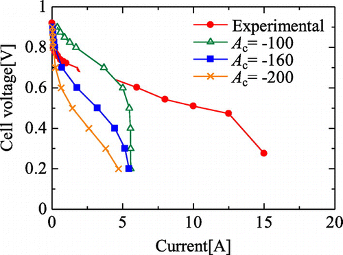
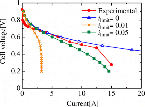
Prior to the simulation of the current density and magnetic flux density distributions, the outputs of each voltage in the form of the I–V curve of the PEMFC need to be modeled. The Tafel slope Ac, the active surface area av, m, and the limiting current density ilim impact the I–V curve and are difficult to measure from the PEMFC stack. Therefore, these values were changed and fitted to the experimental I–V curve. In this simulation, the current distribution at the MEA was uniform.
Figure shows the I–V curves for each of the Tafel slopes. In this simulation, the active surface area was 1 × 10⁴ m−1 and the limiting current density was 0.05 A/cm2. This slope expressed is the reaction rate at the cathode of MEA, and the greater the slope, the greater the voltage drop with low current. This is in accord with theoretical predictions, as the values calculated from previous study results (Citation15–18) fell within the same range, between −100 and −300 V, differing by the catalyst conditions and the reaction rates of PEMFC.
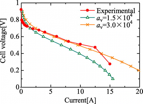
Figure shows the I–V curve for each of the active surface areas. The area is difficult to calculate because it is the actual reaction area, not the MEA area. In this simulation, the Tafel slope is −150 mV and the limiting current density is 0.085 A/cm2. From Equation (6), we see that the sum of all reaction currents appears as a source, and so we can conclude that the output current was large because of the large active area. The curve of the active area is fitted within a medium current range.
Figure shows the I–V curves for each of the limit current densities. The current densities were calculated from the I–V curves because the exhaust of water and the reaction rate of fuel were different due to the varying operating conditions and flow channel. In this simulation, the Tafel slope is −150 mV and the active surface area is 3 × 10⁴ m−1. The limiting current density is important to fit in a high current range. When the value equals zero, the curve did not depict the concentration overpotential.
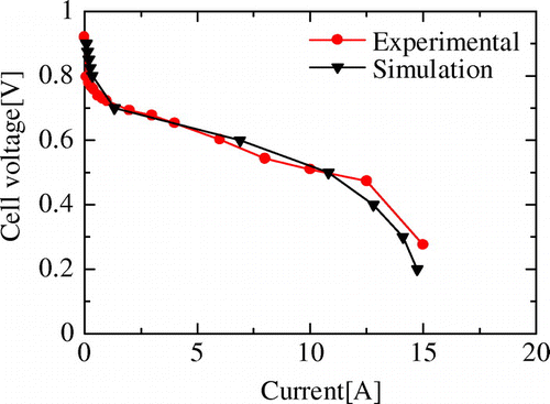
Figure shows the comparison between the simulated and measured I–V curves for the best fitting case. In this simulation, the Tafel slope Ac, the active surface area av, m, and the limiting current density ilim were changed in steps of 10 mV, 1 × 10⁴ m−1, and 0.005 A/cm2, respectively. At the cell voltage of 0.6 V, the Tafel slope Ac, the active surface area av, m, and the limiting current density ilim were −130 mV, 3 × 10⁴ m−1, and 0.045 A/cm2, respectively. In the simulations that follow, this result was used.
4.2. Effect of end terminal
In our previous study, the magnetic flux density distribution tended to be concentrated on each side in the cells because these cells were affected by the end terminals of the stack (Citation14). Here, we investigate the effect of the end terminal on these measurements in more detail.
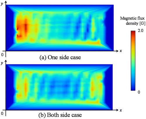
Figure shows the comparison between the magnetic flux density distribution when one side and both sides of the current corrector are connected in 3DFEM simulation. In this simulation, the current density distribution was uniform in the MEA. On both sides of the end terminal, the magnetic flux density distribution was concentrated on both sides in the cell. On the other hand, on one side of the end terminal, the distribution was concentrated only on one side. These results are similar to the previous study (Citation19), where the current density distribution was calculated using an external magnetic flux density, and indicated concentration at the end terminal and the air inlet.
It is worth noting that the relative permeability is important to this result. If the separator is an electromagnetic material such as iron, the effect of the end terminal does not appear because the current density distribution at MEA dominates. However, in this study, the components of PEMFC were made of a paramagnetic material. Therefore, all permeabilities were unity, and the effect of the end terminal appeared.
4.3. Comparison with measurement and simulation
The local current density distribution decreases when a fault such as flooding happens in the cell plane. In our previous study, the decrease at the air flow outlet was the largest in the cell (Citation14). In a different study, the current density distribution decreased at the air outlet when the air stoichiometry decreased (Citation19).
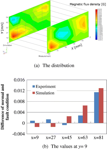
In this study, we reproduced the modeled phenomenon with an experiment. Under normal conditions, the voltages were steady in the experiment and the current distribution was uniform in the simulation. Under fault conditions, the voltages were varied in the experiment and the local current distribution was zero at the nearest outlet of cell, x = 81 and y = 9. This result and the experiment result (Citation14) were compared.
Figure shows the comparison between the normal and fault conditions in the experimental and simulated results. The simulated magnetic flux density distributions were similar to the experimental result. The maximum differences under normal conditions were 0.0114 and 0.0129 G in the experiment and the simulation, respectively, at the nearest outlet of air flow. This result shows that the magnetic fields and current densities are related by Ampere’s law. Moreover, at the other area, the magnetic flux densities varied. But the values were less than half that of the non-uniform magnetic field. The simulation showed a decrease, not only in the local current density but also in the local magnetic flux density distribution at the air flow outlet.
Table shows the measurement and simulation durations. This proposed approach is in situ, and ergo provides a nondestructive means of on-site measurement. At a single site, the measurement completed in a few seconds, while the related simulation lasted 9 ~ 24 h. This is similar to previous studies (Citation7, 19) as 3DFEM simulations involve calculation for numerous elements and meshes. Therefore, the preferable approach is continuous measurement and simulation in the case of PEMFC failure.
Table 2. Measurement and simulation durations
5. Conclusions
This paper describes a nondestructive current distribution measurement approach for use in PEMFC stacks, discusses related simulation results, and compares the simulation and experiment results. To model the PEMFC performance in the simulation, the Tafel slope, active surface area, and limiting current density were varied and fitted to the experimental I–V curve. These values were −130 mV, 3 × 10⁴ m−1, and 0.045 A/cm2 at 0.6 V, respectively. Only the Tafel slope was varied for each voltage because the operating temperatures changed during the experiment.
In order to investigate the effect of the end terminal, the results obtained by connecting both sides and one side of the end terminal were compared. In these results, the effect of the end terminal appeared in the simulation because the components of PEMFC were made of a paramagnetic material.
Finally, the experimental and simulated magnetic flux density distributions were compared. These distributions were similar, and the maximum differences were located at the same point, i.e., the nearest outlet of air flow. From these results, we find that our simulation method provides the magnetic flux density distribution of each PEMFC condition, and shows that it is useful to evaluate the experimental current density through comparison against a simulated result. However, the computation time was over 24 h using 3DFEM simulation, while the measurement described herein applies to control and simple diagnosis applications because it is completed in a few seconds. Therefore, the approach of continuous measurement and performing the simulation on a routine schedule is preferable, because it provides an avenue to discover the unexpected state of the internal condition of PEMFC in simulations including chemical reactions.
Funding
This work was supported by JSPS KAKENHI [grant number JP17K14650].
Additional information
Notes on contributors
Yutaro Akimoto
Yutaro Akimoto is an Associate Professor of the Department of Innovative Electrical and Electronic Engineering at the National Institute of Technology, Oyama College, Japan. His research interests are proton-exchange membrane fuel cells, environment-friendly automobile, and life cycle assessment.
Keiichi Okajima
Keiichi Okajima is a Full Professor of Faculty of Engineering, Information and Systems at the University of Tsukuba, Japan. His research interests are fault detection and PV system, fuel cell system, and life cycle assessment.
References
- Cleghorn, S.J.C.; Derouin, C.R.; Wilson, M.S.; Gottesfeld, S. A Printed Circuit Board Approach to Measuring Current Distribution in a Fuel Cell. J. Applied Electrochemistry 1998, 28, 663–672.10.1023/A:1003206513954
- Ghosh, P.C.; Wüster, T.; Dohle, H.; Kimiaie, N.; Mergel, J.; Stolten, D. In situ approach for current distribution measurement in fuel cells. J. Power Sources 2006, 154, 184–191.10.1016/j.jpowsour.2005.03.219
- Wieser, Ch.; Helmbold, A.; Gülzow, E. A New Technique for Two-Dimensional Current Distribution Measurements in Electrochemical Cells. J. Applied Electrochemistry 2000, 30, 803–807.10.1023/A:1004047412066
- Karimi, A.G.; Jiao, K.; Al Shakhshir, S.; Li., X. Experimental Study on the Effect of Reactant Flow Arrangements on the Current Distribution in Proton Exchange Membrane Fuel Cells. Electrochim. Acta 2011, 56, 2591–2598.
- Hauer, K.-H.; Potthast, R.; Wüster, T.; Stolten, D. Magnetotomography – a New Method for Analyzing Fuel Cell Performance and Quality. J. Power Sources 2005, 143, 67–74.10.1016/j.jpowsour.2004.11.054
- Izumi, M.; Gotoh, Y.; Yamanaka, T. Verification of Measurement Method of Current Distribution in Polymer Electrolyte Fuel Cells. ESC Trans. 2009, 17, 20401–20409.
- Katou, T.; Gotoh, Y.; Takahashi, N.; Izumi, M. Measurement Technique of Distribution of Power Generation Current Using Static Magnetic Field around Polymer Electrolyte Fuel Cell by 3D Inverse Problem FEM. Mater. Trans. 2012, 53, 279–284.10.2320/matertrans.I-M2011842
- Schumacher, J.O.; Eller, J.; Sartoris, G.; Colinart, T.; Seyfang, B.C. 2+1D Modelling of a Polymer Electrolyte Fuel Cell with Glassy-carbon Microstructures. Math. Comput. Model Dyn. Syst. 2012, 18 (4), 355–377.10.1080/13873954.2011.642390
- Nasu, T.; Matsushita, Y.; Okano, J.; Okajima, K. Study of Current Distribution in PEMFC Stack Using Magnetic Sensor Probe. J. international Council on Electrical Engineering 2012, 2, 391–396.10.5370/JICEE.2012.2.4.391
- Okajima, K.; Nasu, T.; Choi, S. Evaluation of 1-kW Class PEM Fuel Cell Stack under In-situ Conditions Considering Individual Cells. J. Energy and Power Engineering 2014, 8, 1543–1551.
- Mench, M.M. Fuel Cell Engines; Wiley: Hoboken, NJ, 2008.10.1002/9780470209769
- Hotta, M.; Hayashi, M.; Lanagan, M.T.; Agrawal, D.K.; Nagata, K. Complex Permittivity of Graphite, Carbon Black and Coal Powders in the Ranges of X-band Frequencies (8.2 to 12.4 GHz) and between 1 and 10 GHz. ISIJ International 2011, 51 (11), 1766–1772.10.2355/isijinternational.51.1766
- Young, H.D.; Francis Weston Sears. “University physics”; San Francisco, CA: Addison Wesley, 1992.
- Akimoto, Y.; Okajima, K. Experimental Study of Non-Destructive Approach on PEMFC Stack Using Tri-Axis Magnetic Sensor Probe. J. Power and Energy Engineering 2015, 03, 1–8.10.4236/jpee.2015.33001
- Squadrito, G.; Maggio, G.; Passalacqua, E.; Lufrano, F.; Patti, A. An Empirical Equation for Polymer Electrolyte Fuel Cell (PEFC) Behavior. J. Applied Electrochemistry 1999, 29, 1449–1455.10.1023/A:1003890219394
- Haji, S. Analytical Modeling of PEM Fuel Cell i–V Curve. Renewable Energy 2011, 36, 451–458.10.1016/j.renene.2010.07.007
- Laurencelle, F.; Chahine, R.; Hamelin, J.; Fournier, M.; Bose, T.K.; Laperriere, A. Characterization of a Ballard MK5-E Proton Exchange Membrane Stack. Fuel Cells 2001, 1 (1), 66–71.10.1002/(ISSN)1615-6854
- Akimoto, Y.; Okajima, K. Semi-Empirical Equation of PEMFC Considering Operation Temperature. Energy Technology & Policy 2014, 1 (1), 91–96.10.1080/23317000.2014.972480
- Le Ny, M.; Chadebec, O.; Cauffet, G.; Rosini, S.; Bultel, Y. PEMFC Stack Diagnosis Based on External Magnetic Field Measurements. J. Appl. Electrochem. 2015, 45, 667–677.10.1007/s10800-015-0844-x

