
 ?Mathematical formulae have been encoded as MathML and are displayed in this HTML version using MathJax in order to improve their display. Uncheck the box to turn MathJax off. This feature requires Javascript. Click on a formula to zoom.
Abstract
In the present study, a set-up and a rapid method were developed to determine the isoelectric point (pI) of gelatin based on the combination of an automatic adding solution technique and fiber-optic refractive index sensing. The refractive index of the gelatin aqueous solution was measured as a function of pH and time using a fiber-optic sensor and pH meter. This is a typical acid-base titration process. The peak pH values of the refractive index-pH curve indicate the pI of the gelatins. With the aid of virtual instrument technology, the data acquisition, process and display were automatic, having the advantages of quick and labor saving. Furthermore, this improved analysis efficiency and reduced manual disturbance, which was typically an approximately 15 min period. The pI of these two kinds of gelatin, sample 1 and 2 were determined through this method and the pI s were consistent with the values obtained using a rotary viscometer. The test results revealed that this method is rapid, sensitive, accurate, and labor and reagent saving, and has the potential for the rapid determination of the pI of amino acids and proteins.
GRAPHICAL ABSTRACT
PUBLIC INTEREST STATEMENT
Gelatin is a kind of low calorie health food with high nutritional value, which can be used to make confectionery additives, frozen food additives and so on. In addition, gelatin is widely used in medicine and chemical industry. Isoelectric point (pI) is one of the most important physical and chemical properties of gelatin, which will affect its application to a great extent. Therefore, the accurate determination of the pI of gelatin is of great academic significance as well as potential application price in some aspects. The research aim is to develop a new, rapid, simple and accurate technology to determine the pI of gelatin. The method is easy to operate. The results show that the method is reliable.
1. Introduction
The isoelectric point (pI) of an amphoteric substance may be defined as the hydrogen ion activity of a solution or suspension, in which the ampholyte shows no migration in an electric field (Hardy, Citation1899). The pI is one of the most important parameters to reflect the molecular structure of ampholytes. Many of the physical and chemical properties of amphoteric substances, such as solubility, viscosity, osmotic pressure, maximum opacity and cataphoresis, are closely correlated to the charge on ampholyte ions, and have been used in the measurement of its pIs. In recent years, the determination of the pI of ampholytes has become increasingly important as the complexity of the (especially protein) structure increases. The traditional methods for the determination of the pI have been reported based on the measurements of the physical properties of ampholytes at the pI, such as viscosity (Hitchcock, Citation1924; Liang, Hawkett, & Tanner, Citation2005), light-scattering intensity (Verma, Aswal, Kulshreshtha, Hassan, & Kaler, Citation2008), osmotic pressure (Hitchcock, Citation1929), turbidity (Hitchcock, Citation1929), adhesion of latex particles (Lefèvre et al., Citation2009) and oscillating (Maldonado, Vara, & Sillero, Citation2008; Sillero & Maldonado, Citation2006). These methods are simple. However, these are rarely used at present most probably due to its low sensitivity. Due to the higher sensitivity of capillary electrophoresis (CE) relative to classical methods, it has been widely accepted as the mainstream method for the determination of the pI. To date, various analytical techniques based on CE, including isoelectric focusing (IEF) (Bush & Currie, Citation1992; Herzog et al., Citation2016; Higgins, Limcango, & Jung, Citation2012; Poehler et al., Citation2015) and capillary isoelectric focusing (CIEF) (Goodridge, Goodridge, Wu, Griffiths, & Pawliszyn, Citation2004; Lecoeur, Gareil, & Varenne, Citation2010; Lecoeur, Goossens, Vaccher, Bonte, & Foulon, Citation2011; Li et al., Citation2004; Righetti, Citation2004; Thomassen, van Eikenhorst, van der Pol, & Bakker, Citation2013), have been employed in determining the pI values of ampholytes. These methods are sensitive and rapid. IEF is a high-resolution technique, while CIEF is a rapid and powerful analytical technique for separating and measuring the pI, which combines the high resolving power of conventional IEF with the automation and quantification of CE. However, these methods have disadvantages of complex operation and professional training.
Optical fiber refractive index sensors allow for the fast, sensitive and selective analysis of different parameters. The refractive index sensor invented by our laboratory has been successfully applied in determining the critical micelle concentration of surfactants (Tan, Huang, & Huang, Citation2010) and the deacetylation degree of chitosans (Tan, He, Meng, & Huang, Citation2012). In the present study, an optical fiber refractive index sensor combined with an automatic mixing system was proposed for the determination of the pI of gelatins. The processes of data acquisition, analysis, display and storage were realized through virtual instruments. The determination of pI was based on the automated measurement and display of time-dependent changes in the refractive index and pH. The peak pH value of the refractive index-PH plot indicates the pI. In the present study, novel technique and the viscosity method were compared in detail. With the novel technique, the pI values of two kinds of gelatin were determined, and the results were inconsistent with the results obtained using the viscosity method.
2. Measurement method
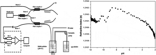
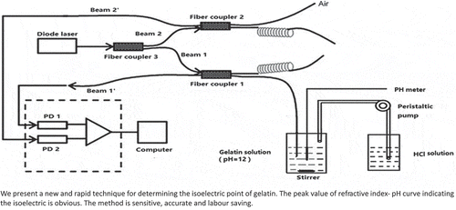
In this article, the refractive index of gelatin solution was measured using a fiber sensor based on a two-channel Fresnel reflection technique, a fiber sensor based on two-channel Fresnel reflection technique is used (Tan et al., Citation2010). The experiment setup for the fiber-optic sensor is sketched in Figure . It consists of a light source, three single-mode fused couplers, two photodetectors (PDs), and two optical fibers with sensing ends. The light source is a diode laser source operated in wavelength of 1550 nm in the experiment. Split ratios of Coupler 1, 2 and 3 are respectively 50:50, 50:50 and 10:90. All fibers used are Corning SMF-28 fibers. The light sent from the diode source is first split into two beams (Beam 1 and Beam 2, shown in Figure ) by Coupler 3. Beam 1 with higher intensity passes through Coupler 1 and reflected by the sensor–solution interface, while Beam 2 with lower intensity (as reference beam) passes through Coupler 2 and reflected by the sensor–air interface. The lights split into two twisted fibers are completely attenuated to avoid harmful reflection noise. Two reflected lights of Beam 1ʹ and Beam 2ʹ (shown in Figure ) are respectively detected by the PD1 and PD2 after crossed Coupler 1 or 2, as shown in Figure . The intensity received by PD1 can be obtained by Fresnel formula
Figure 1. Schematic of apparatus including reservoirs for solvent, peristaltic pump to deliver HCl into the mixing chamber, the peristaltic pump is controlled manually, optical power meter is controlled by the computer.
Likewise, the reflected intensity collected by PD2 is given by
Here is the output intensity of light source,
the effective index of the single-mode fiber,
and
are respectively the indices of the solution and air.
,
,
,
,
, and
are respectively the transmittances of bar-state or cross-state of Couplers 1, 2 and 3. If insertion losses of the couplers can be neglected, the transmittances should satisfy the following formulas:
,
,
. From Equations (1) and (2), the relative reflective intensity
can be obtained as follows:
Equations (3) can be rewritten as follows:
where . Apparently, the value of
is a constant which is only determined by the transmittances of the couplers.
When the probe fiber is exposed to the air environment, is equal to
. From Equation (4) one obtains
Therefore, the value of can be measured directly and conveniently in the setup, avoiding the troubles of transmittance measurements and calculation.
From Equations (3) and (4) one obtains
The refractive index of air of is 1.0003. The effective index
of the fiber mode can be calculated from the known fiber group index
and the dispersion relation.
The automatic solution mixing system is realized through the peristaltic pump. In this article, one of the two optical fibers is used as the sensing tip, another as the reference arm, which is exposed to the air environment, used to eliminate the influence of light source fluctuation. In addition, the undesirable effects or the errors coming from the different losses of fibers and couplers and environment temperature can be also decreased.
The effective index nf of the fiber mode is 1.44961 at λ = 1550 nm.
3. Materials and methods
3.1. Software measurement
The virtual instrument system developed based on LabVIEW 8.6 for the sensor can measure and display the refractive index in a gelatin solution. It can display and automatically process the testing data in real time. The system software consists of three main parts: operation panel, data acquiring and real-time display, and data storage. The DAQ board mainly plays the role of signal acquisition, and the communication of the computer and the optical power meter are realized through serial port RS232. In the present study, the refractive index change information of the gelatin solution can be displayed on the monitoring screen in real time. This method greatly simplifies the experimental operation, avoids the complicated procedures of manual processing of data and personal error, and improves the veracity and repeatability of the experiment results.
3.2. Materials
Sample 1 (gelatin) was purchased from Tianjin Kemiou Chemical Reagent Co. Ltd., while sample 2 (gelatin) was purchased from Tianjin Zhiyuan Chemical Reagent Co. Ltd. All products used had a purity of >99%. The gelatin working solutions were prepared before use by dissolving the desired amount of gelatin in deionized water.
3.3. Instrumentation
A mixing cylinder (100-ml mixing beaker) equipped with a magnetic stirrer was used as a mixing chamber for the solutions. A peristaltic pump continuously transferred the NaOH solution of another 100-ml beaker into the mixing chamber. Then, the sensing optical fiber and the electrode of the pH meter were dipped into the mixed solution to simultaneously determine the refractive index and pH value of the mixed solution. Two Lightcomm OPM2012AA optical power meters were installed in parallel, as indicated in the schematics in Figure . The analog output of the optical power meter was connected to a computer via the RS-232C port, and was used to monitor and collect the reflective intensity-time (R-t) data. The apparatus was controlled by a computer with MS Windows and home-built software written in LabVIEW.
The viscosity of the gelatin solution was measured using a NDJ-1 rotary viscosimeter (Shanghai Jinghai Instrument Co. Ltd.). An on-line pH meter (Guangzhou Huigu Environment Technology Co. Ltd.) is used to collect the pH-time data.
3.4. Experimental procedure
A 100-ml beaker served as a titration vessel. Fifty ml of the gelatin solution (before the test, the pH value was adjusted to 12 with the NaOH solution) was transferred to the beaker. The sensing tip of the optical fiber refractive index sensor and the electrode of the pH meter are immersed into the solution. Then, the sample solution was titrated with 0.1 M of HCl while stirring using a magnetic stirrer. After system calibration, the typical experiment began with the press of the “Start” button. The peristalsis pump and magnetic stirrer started running. With the injection of the HCl solution, the gelatin solution gradually changed from acidic to alkaline, and the pH value varied downward. The experimental factors in each test were optimized to ensure perfect data acquisition. Typically, this was an approximately 15-minute period. In the course of the experiment, the change in pH value of the gelatin solution was collected using a pH meter. Then, the intensity of the reflected light coming from the sensing tip was automatically collected at regular intervals (typically 1–5 s) using the control program, converted into the refractive index, and displayed in the virtual panel in real time. The refractive index vs. time plot was simultaneously displayed, and the raw data were saved in Excel format for analysis.
Finally, the curve of refractive index-pH of the gelatin solution was obtained, and the peak pH value was considered as the pI of the sample.
All of the measurements were carried out at room temperature (298.15 K).
Each experiment was run in triplicate with separate mixtures.
4. Results and discussion
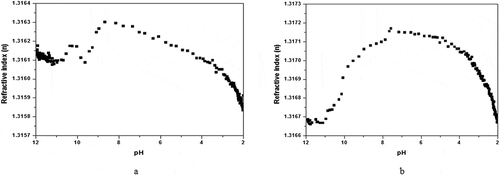
NaOH solution was added to the sample in a relatively high concentration (0.01 M), in order to strengthen the alkaline of the solution. With the high initial pH of the solution (pH = 12), the typical refractive index titration curves resulting from the titrations of the alkaline gelatin solution with hydrochloric acids are presented in Figure . As presented in Figure , for sample 1, the addition of acid gave rise to a small decrease in refractive index at the beginning of the curve, with a pH interval ranging within (~12)-(~11). Then, there was a refractive index jump in the pH interval of (~11)-(~10). Subsequently, the curve turned downward again until the pH value dropped near 9.5. Afterwards, the refractive index significantly increased, reaching the maximum of the curve, which corresponded to a pH of 8.86, indicating the pI of sample 1. After the maximum was reached, the curve slowly decreased from pH 8.86 to pH 2.00. Curve b was similar to curve a. The slight difference was that curve b only had one falling process before reaching the maximum, and was bell-shaped. For sample 2, the peak pH value was 7.57 and the pI was pH 7.57.
Figure 2. Titration of gelatin solutions (initial pH = 12) with 0.1M hydrochloric acid at 298.15K. The flow velocity of HCl solution is 2mL/min, typically a 15-min period, the sampling. (a), sample 1(1.5% gelatin solution); (b), sample 2 (1% gelatin solution).
The refractive index is one of the important physicochemical properties of the gelatin solution, which is correlated to the size and shape of the solute molecule, solvent properties, temperature, and solute concentration. By means of studying the refractive index of the gelatin solution, the size and shape change of gelatin molecules in the solution can be deduced. The refractive index of the gelatin solution changes with pH, and the essential reason lies gelatin molecular deformation. At a certain pH value, the gelatin molecule is electrically neutral. In other words, according to Horiuchi’s interpretation, the point where the gelatin radical has equal positive and negative charges is the pI. Electrical neutrality makes the intermolecular repulsion stay at a minimum, causes molecular shrinkage. At this point, the molecule closely binds the most, and the refractive index of the solution has the maximum value. When the pH value of the solution deviates from the pI, which increases or decreases, the refractive index of the solution decreases, the net charge of gelatin molecules increases with the deviation from the pI, and the electrostatic repulsion would make the gelatin chains unfold. The different shapes of gelatin molecules in different pH solutions have great influence on the refractive index of the solution. Based on this, the pH of gelatin solutions can be changed with acid or alkali, the peak pH value of the refractive index-pH curve can be plotted, and the corresponding pI can be obtained.
Relevant experiments have revealed that the pI is independent of the concentration of the gelatin. Therefore, the influence of the gelatin concentration on the pI was not considered in the present study.
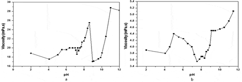
In order to further confirm the effectiveness of the system, in contrast, the viscosities of these two samples were measured under different pH values using a NDJ-1 rotary viscometer.
The viscosity of the gelatin solution was at a minimum at the pI. The minimum in the case of viscosity is quite sharp, and could easily be detected by preparing gelatin solutions at various pH levels, determining the viscosities of these solutions, and graphically finding the pH for minimum viscosity.
Viscosity test: A NDJ-1 rotary viscometer and pH meter was used for the present experiment. The gelatin stock solution should be prepared the day before the experiment, in order to allow it to age to constant viscosity.
Two concentrations, 6.7% (sample 1) and 25% (sample 2), by weight stock gelatin solution, were used for the experiment. For each sample, a series of gelatin solutions with different pH values were prepared by adding certain amounts of hydrochloric acid or sodium hydroxide solutions. All solutions have the same percentage concentration of gelatin to the certain sample. Before the test, 80 ml of gelatin solution was transferred into a 100-ml beaker for measurement.
The viscosities of the two sample solutions are measured, and the plots of viscosity vs. pH were prepared, as shown in Figure . It can be observed from Figure that the pIs were determined from the minimum viscosity value of the viscosity-pH curves. The minimum viscosities of sample 1 and sample 2 were found to be near pH 8.96 and pH 7.53, respectively. Hence, the pIs of these two samples may be taken as pH 8.96 and 7.53.
Figure 3. Effect of pH on viscosity of gelatin solutions at 298.15K. (a), sample 1, 6.7% gelatin solution, number 1 rotor of the viscometer is used; (b), sample 2, 25% gelatin solution, number 0 rotor of the viscometer is used.
The pIs measured by our technique and the viscosity method are presented in Table . The comparative results show that the pI values determined by our technique are in good agreement with that of the viscosity method. However, for the traditional viscosity method, its experimental operation is quite time-consuming. Moreover, it wastes a lot of reagents. On the contrary, the technique in the present study is time saving. In addition, the curves of the refractive index-time can be automatically plotted, and the pI can be easily obtained. In this article, the instrument measurement precision is 0.01dBm, and the refractive index resolution can be reached to 1 × 10⁻⁵ refractive index unit.
Table 1. The Comparison of the fiber-optic sensor and the viscosity method
These results demonstrate the usefulness of monitoring a titration by means of the fiber-optical system. The pI can be obtained through the monitoring system.
5. Conclusion
An accurate and rapid method to determine pIs by means of an optical fiber refractive index sensor was described. Using this technique, the pIs of two kinds of gelatin were determined and compared in terms of viscosity. The experimental results revealed that the present method was rapid, inexpensive, sensitive, precise, easy to operate, time saving and suitable for unskilled operators. Furthermore, the present method has the potential of determining the pI of proteins and amino acids, and its related work is in progress.
Competing interests
The authors declare no competing interests.
Cover image
Source: Hui Su, Xu Guang Huang. Fresnel-reflection-based fiber sensor for on-line measurement of solute concentration in solutions. Sensors and Acutators B, 126 (2007) 579-582.
Correction
This article has been republished with minor changes. These changes do not impact the academic content of the article.
Acknowledgements
The authors gratefully acknowledge the financial support for this work from the Science and Technology Program of Guangzhou, China (201607010096)
Additional information
Funding
Notes on contributors

Chun Hua Tan
Chun Hua Tan, the corresponding author, is working as Associate Professor in South China Normal University, Guangzhou, China. He has received the Master of Science (Analytical Chemistry) degrees from China University of Geosciences of Wuhan, China, in June, 2000, and received the Doctor of Science (Optics) degrees from South China Normal University of Guangzhou, China, in June, 2005. His research interests are aimed at analytical chemistry and optical fiber sensing. The main research focus of his research group is to develop simple fiber-optic sensing technology for the determination of chemical parameters and to develop new fluorescent materials and studying their applications.
References
- Bush, E., & Currie, R. A. (1992). Determination of transcription factor isoelectric point by two-dimensional native isoelectric focusing and electrophoretic mobility shift analysis. Analytical Biochemistry, 206(1), 189–194. doi:10.1016/S0003-2697(05)80032-6
- Goodridge, L., Goodridge, C., Wu, J., Griffiths, M., & Pawliszyn, J. (2004). Isoelectric point determination of norovirus virus-like particles by capillary isoelectric focusing with whole column imaging detection. Analytical Chemistry, 76(1), 48–52. doi:10.1021/ac034848s
- Hardy, W. B. (1899). A preliminary investigation of the conditions which determine the stability of irreversible hydrosols. Proceedings of the Royal Society of London, 66, 110–125. doi:10.1098/rspl.1899.0081
- Herzog, C., Poehler, E., Peretzki, A. J., Borisov, S. M., Aigner, D., & Mayr, T. (2016). Continuous on-chip fluorescence labelling, free-flow isoelectric focusing and marker-free isoelectric point determination of proteins and peptides. Lab on a Chip, 16(9), 1565–1572. doi:10.1039/C6LC00055J
- Higgins, T. N., Limcango, M., & Jung, B. (2012). Evaluation of the Sebia isoelectric focusing method for alpha 1 antripsin phenotype determination. Clinical Biochemistry, 45(13–14), 1109. doi:10.1016/j.clinbiochem.2012.07.036
- Hitchcock, D. I. (1924). The isoelectric point of gelatin at 40℃. The Journal of General Physiology, 7(5), 457–462. doi:10.1085/jgp.6.4.457
- Hitchcock, D. I. (1929). The combination of gelatin with hydrochloric acid: II. New determinations of the isoelectric point and combining capacity of a purified gelatin. Journal of General Physiology, 12(4), 495–509. doi:10.1085/jgp.12.4.495
- Lecoeur, M., Gareil, P., & Varenne, A. (2010). Separation and quantitation of milk whey proteins of close isoelectric points by on-line capillaryisoelectric focusing Electrospray ionization mass spectrometry in glycerol-water media. Journal of Chromatography A, 1217(46), 7293–7301. doi:10.1016/j.chroma.2010.09.043
- Lecoeur, M., Goossens, J.-F., Vaccher, C., Bonte, J.-P., & Foulon, C. (2011). A multivariate approach for the determination of isoelectric point of human carbonic anhydrase isoforms by capillary isoelectric focusing. Electrophoresis, 32(20), 2857–2866. doi:10.1002/elps.201100219
- Lefèvre, G., Cerović, L., Milonjić, S., Fédoroff, M., Finne, J., & Jaubertie, A. (2009). Determination of isoelectric points of metals and metallic alloys by adhesion of latex particles. Journal of Colloid and Interface Science, 337(2): 449–455.
- Li, G., Zhou, X., Wang, Y., El-Shafey, A., Chiu, N. H., & Krull, I. S. (2004). Capillary isoelectric focusing and affinity capillary electrophoresis approaches for the determination of binding constants for antibodies to the prion protein. Journal of Chromatography A, 1053(1–2), 253–262. doi:10.1016/S0021-9673(04)01497-9
- Liang, G. H. G., Hawkett, B. S., & Tanner, R. I. (2005). The determination of the isoelectric point from measurements of dispersion viscosity as a function of pH. Journal of Dispersion Science and Technology, 26(4), 469–472. doi:10.1081/DIS-200054583
- Maldonado, A., Vara, F., & Sillero, A. (2008). Improved application of the oscillating method for the isoelectric point determination of protein: Potential connection with protein data banks. Computers in Biology and Medicine, 38(1), 23–30. doi:10.1016/j.compbiomed.2007.06.004
- Poehler, E., Herzog, C., Lotter, C., Pfeiffer, S. A., Aigner, D., & Mayr, T. (2015). Label-free microfluidic free-flow isoelectric focusing, pH gradient sensing and near real-time isoelectric point determination of biomolecules and blood plasma fractions. Analyst, 140(22), 7496–7502. doi:10.1039/C5AN01345C
- Righetti, P. G. (2004). Determination of the isoelectric point of proteins by capillary isoelectric focusing. Journal of Chromatography A, 1037(1–2), 491–499. doi:10.1016/j.chroma.2003.11.025
- Sillero, A., & Maldonado, A. (2006). Isoelectric point determination of proteins and other macromolecules: Oscillating method. Computers in Biology and Medicine, 36(2), 157–166. doi:10.1016/j.compbiomed.2004.09.006
- Tan, C. H., He, W. X., Meng, H. Y., & Huang, X. G. (2012). A new method based on fiber-optic sensing for the determination of deacetylation degree of chitosans. Carbohydrate Research, 348, 64–68. doi:10.1016/j.carres.2011.04.047
- Tan, C. H., Huang, Z. J., & Huang, X. G. (2010). Rapid determination of surfactant critical micelle concentration in aqueous solutions using fiber-optic refractive index sensing. Analytical Biochemistry, 401, 144–147. doi:10.1016/j.ab.2010.02.021
- Thomassen, Y. E., van Eikenhorst, G., van der Pol, L. A., & Bakker, W. A. M. (2013). Isoelectric point determination of live polioviruses by capillary isoelectric focusing with whole column imaging detection. Analytical Chemistry, 85(12), 6089–6094. doi:10.1021/ac400968q
- Verma, G., Aswal, V. K., Kulshreshtha, S. K., Hassan, P. A., & Kaler, E. W. (2008). Adsorbed anthranilic acid molecules cause charge reversal of nonionic micelles. Langmuir, 24(3), 683–687. doi:10.1021/la7020726